Vibration Control of a Gym Floor Using Tuned Mass
Dampers: A Numerical Analysis
Marcos Daniel Souza dos Santos, Daniel Valença Fiuza Lima, Jorge Eliécer Campuzano Carmona, Suzana Moreira Avila, Graciela Nora Doz de Carvalho
Departamento de Engenharia Civil e Ambiental, Faculdade de Tecnologia, Universidade de Brasilia, Brasilia, Brasil Email: [email protected], [email protected], [email protected], [email protected], [email protected]
Received May 23, 2013; revised June 26, 2013; accepted July 7,2013
Copyright © 2013 Marcos Daniel Souza dos Santos et al. This is an open access article distributed under the Creative Commons Attribu-tion License, which permits unrestricted use, distribuAttribu-tion, and reproducAttribu-tion in any medium, provided the original work is properly cited.
ABSTRACT
This work presents a study on excessive vibration problem occurring on concrete slabs, usually used on residential and commercial building floors. Even well designed slabs, according to ultimate and serviceability limit states criteria, can be vulnerable to undesirable vibrations that lead to user discomfort. A gym floor, that presented real excessive vibrations, located in a commercial building situated in the city of Brasilia, Brazil, was analyzed via Finite Element Method using ANSYS software. The first step in this analysis was to obtain natural frequencies and vibration modes, the structure presented low natural frequencies representing its flexible behavior. Then it was simulated a dynamic loading of people jumping, characteristic of this type of building occupation. Since it was observed the occurrence of excessive vibrations also in the numerical analysis, a Tuned Mass Damper (TMD) control system was proposed, looking for the best set of dampers to improve the control performance. The parameters for the best vibration reduction were obtained via a para- metric study considering four different slabs varying dimensions and support conditions. Different models considering one and more TMDs, varying its placements and parameters, besides the frequency reference value to tune the damper were considered. An efficient control solution to this practical problem is presented to reduce its undesirable vibrations.
Keywords: Structural Dynamics; Structural Control; Concrete Slabs; Tuned Mass Damper
1. Introduction
Human induced loads can cause excessive vibration lead- ing to discomfort and even compromising structural sa- fety. Real occurrences of this problem in structures sub- jected to loads originated from people movement are wor- ldwide known, a famous example is the London Mille- nium Footbridge [1]. Floor vibration studies have inten- sified in the last years. A number of factors cause this effect; the more important are: the use of more resistant materials that lead to more slender and flexible slabs, and the occurrence of non-provided activities in the original structural design. Those things have contributed to in- creasing emergence of excessive vibration on structures, especially on slabs [2,3]. This problem is directly linked to the structural control devices study. Structural control provide changes on stiffness and damping properties of the system, installing external devices or applying exter-nal forces, aiming to reduce origiexter-nal structure vibrations. Among several structural control devices there is the Tuned Mass Damper (TMD), a damper applied in many practical cases, such as high buildings, footbridges, tow-
ers, etc. [4]. It is a mass-spring-dashpot system connected to the structure in a way to vibrate out of phase with the main structure, if tuned to the appropriated frequency. In this way the energy is transferred to the TMD reducing amplitude vibration on the main system. The use of TMD to reduce floor vibration has been studied by many re- searchers lately [5-9]; however there are still many topics to further development, such as the determination of ap- propriate TMD parameters to optimize control perform- ance. This work presents a floor vibration study to a prac- tical case of a gym. The slab analyzed presented exces- sive vibration problems when subjected to typical human induced loading of rhythmic exercise practicing. A con- trol system consisting of various TMD was proposed. This proposal was based on a parametrical study to improve the performance of a slab set with typical dimensions of structures like residential and commercial buildings.
2. Human Induced Vibrations
duced loads, can cause undesirable excessive vibrations. Thus the understanding of structural dynamic behavior and the characteristics of the dynamic load is very im- portant, particularly to floor slabs. Dynamic loading can produce high vibration levels than can cause discomfort to users and even compromise structural safety. Occur- rence’s of these problems are well known worldwide, like the already mentioned London Millenium Footbridge [1]. The stadium grandstands collapse in the 1920 years lead the American Standards Association (ASA, atual ANSI—American National Standards Institute) to nomi- nate a committee to establish safety standards for this type of structure. Decades later, researchers described mathematically human loading arising from typical ac- tivities using a Fourier series. Faisca [10] performed an experimental study focusing on this type of load, de- scribing human induced dynamic load considering loss of contact with the structure. According to her, these loads can change depending on structure’s flexibility, namely they depend on people-structure interaction. Varela [5] studied human induced loading correlating the mathe- matical model with experimental results.
3. Structural Control: Tuned Mass Damper
(TMD)
Tuned Mass Damper reduces the energy dissipation re- quest of structural members when subjected to dynamic loads. This reduction occurs by transferring a portion of the vibratory energy to the TMD that in its simplest con-ception is a mass-spring-dashpot system connected to the structure, like shown on Figure 1. Considering the main system like a single-degree-of-freedom model, with mass
M, damping C and stiffness K, on which is applied a dy-namic load f(t) and attached a TMD with mass m, damping
c and stiffness k, the equations of motion are:
( )
My t Cy t Ky t cz t kz t f t (1)
mz t cz t kz t my t (2) where:
ÿ(t): main system acceleration;
y(t): main system velocity;
y(t): main system displacement;
z(t): relative displacemente between the TMD and the main system.
When installed, the TMD tries to bring resonance peaks to lower values; this effect is desirable occurring on a wide frequency range.
For this to happen, TMD optimum parameters should be obtained, improving the control system performance [11]. A large number of these devices have been installed in high buildings, bridges, towers and industrial chim- neys to control the dynamic response due to strong winds mostly [2]. In recent years studies were developed to
y(t)
f(t)
z(t)
m
K
C M
[image:2.595.357.476.87.226.2]c k
Figure 1. Structural system model with a TMD installed [4].
harness the potential of TMD on floor vibration control. Battista & Varella [12] presented a practical case of us-ing TMDs in commercial buildus-ing with metallic beams and composite floor decks that presented excessive vi-bration levels according to ISO 2631/1, ISO 2631/2 and NBR 8800 ABNT codes. Setareh et al. [8] describe the application of a passive pendulum working as a TMD for two cases with excessive slab vibrations. In this study they emphasize men-structure interaction on experimen-tal results obtained.
4. TMD Parametric Study
The four slab structures studied in this work are shown in Figure 2. The loading applied simulated people on the move.In all cases analyzed it was verified vibration levels higher than those recommended on standard codes. Thus it was performed a study analyzing different TMD con- figurations in a way to verify the best control proposal for each one of the slabs. This study also analyzed the influ- ence of TMD parameters on the control strategy per- formance. Because of the absence of design criteria to set parameters to TMD installed on floors, it was performed a parametrical study varying the mass ratio μ, the frequency ratio α and the damping ratio ξ, and verifying for each set of parameters the TMD efficiency. The four models pre- sented natural frequencies near of values that characterize human dynamic loads. On the first slab studied, simply supported at the four edges, the best configuration ob- tained was a single TMD placed at the midspan, it reduced on 75% displacement amplitude.
Table 1 presents the bests reductions for each slab, applying harmonic loading and human-induced loading, associated frequency ratios are also presented. It can be verified that best reductions were obtained considering the theoretical harmonic loading compared to human-induced loading. In the case of Slab 1, the best verified value of α
6 m
Simply Supported
Fr
e
e
Fr
e
e
5 m
8 m
Simply Supported
Simply Supported
Simply Supported
Clamp
e
d
Simply Supported
Simpl
y Supp
orted
Fr
e
e
Clamp
e
d
Clamp
e
d
Clamped
Clamped
15 m
9 m
Slab 1 Slab 2
Slab 3 Slab 4
Simply Supported
12 m
6 m
Simpl
y Supp
orted
[image:3.595.132.468.82.346.2]8 m
Figure 2. Dimensions and support conditions of the four slab models analyzed.
Table 1. Parametrical study results: frequency ratio and displacement reduction.
Type of loading Number of TMDs Position α Displ. reduction (%)
Harmonic 1 Midspan 0.95 74.58
Slab 01
Human-induced 12 people 1 Midspan 0.98 45.70
Harmonic 2 1 m from the border 1.03 73.12
Slab 02
Human-induced 8 people 2 At the border 1.10 54.65
Harmonic 1 0.8 m from the border 1.00 79.90
Slab 03
Human-induced 8 people 1 At the border 1.25 67.6
Harmonic 1 Midspan 0.95 72.09
Slab 04
Human-induced 8 people 1 Midspan 1.00 56.00
5. Analysis of a Gym Slab
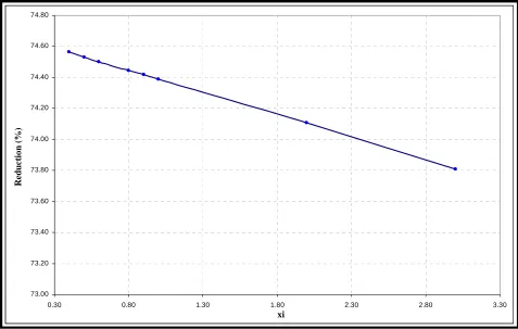
performance. The more increase applied to mass ratio, bestis the efficiency. However, this parameter requires special attention because the damper weight increase can lead to excessive static deformations, compromising structural safety. The parametric studies performed allowed to ob- serve the influence of the frequency ratio (α) change in the displacement reducing, shown in Figure 3, as well as mass ratio (μ) and damping ratio influence (ξ), repre- sented on Figures 4 and 5. Similar studies were per- formed by in the other slabs shown in Figure 2, they are well detailed on the work of Santos [13]. Numerical simulations indicated that the parameter which design should be more careful, since it has a great influence on final results, is the frequency ratio α. Damping ratio ξ and mass ratio μ didn’t show the same influence.
A gym floor, that presented excessive vibrations, located in a commercial building situated in the city of Brasilia, Brazil, was analyzed via Finite Element Method using ANSYS software. The commercial building has five floors: a basement, downstairs, first and second floor and roof. All floors were built as concrete solid slabs with 15 MP a resistance, 7 cm of thickness, supported by beams and columns of rectangular section.
[image:3.595.53.541.387.541.2]Red
ut
ion (%
)
0.55 0.65 0.75 0.85 0.95 1.05 1.15 1.25
Alpha 40.000
[image:4.595.64.536.87.384.2]45.000 50.000 55.000 60.000 65.000 70.000 75.000 80.000
Figure 3. Frequency ratio α influence on displacement reduction (μ = 0.10 and ξ = 0.40) Slab 1.
73.00 73.20 73.40 73.60 73.80 74.00 74.20 74.40 74.60 74.80
0.30 0.80 1.30 1.80 2.30 2.80 3.30
Alfa
R
ed
u
ção
(%
)
xi
Re
duc
ti
o
n
(%
)
[image:4.595.59.536.413.716.2]60.0000 65.0000 70.0000 75.0000 80.0000 85.0000
0.04 0.09 0.14 0.19 0.24
Alfa
R
e
d
u
ção
(%
)
mu
Reductio
n
(
%
[image:5.595.66.535.84.390.2])
Figure 5. Mass ratio influence μ on displacement reduction (ξ = 0.4 and α = 0.96) Slab 1.
X
P29 (20 × 30)
P35 (20 × 30)
Wall 2 (12 × 335) V1 (50 × 50)
y
14.075
6.
49
V1
3
(20
×
5
0)
V9 (30 × 50)
Wa
ll 4
(
12
×
11
7)
0.61 2.235
2.84 3.475
3.475
P27 (20 × 30) P28 (20 × 30)
P34 (20 × 30) P33 (20 × 30)
V1
4
(20
× 50
)
V1
5
(20
×
5
0)
V1
6
(20
×
5
0)
V1
7
(12
×
5
0)
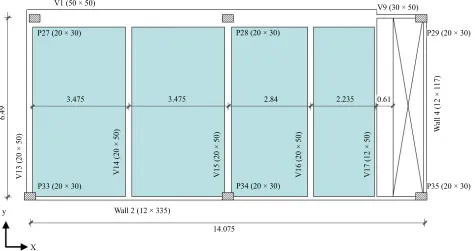
Figure 6. Dimensions and structural sketch of the gym floor portion studied.
were: Modulus of Elasticity of 29 Gpa; density of 2500 kg/m3 and Poisson ratio of 0.3. The studied slab was
modeled with a finite element mesh in the XY plane,
using SHELL63 elements. Beams were modeled using BEAM4, as well as columns.
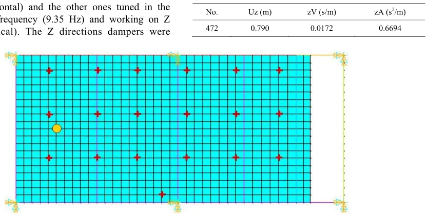
[image:5.595.63.538.419.670.2]of those from human induced loads. The first three mode shapes are in the horizontal direction with bending of the columns in the first mode and column bending and tor- sion in the second and third modes. From the fourth mode arise vertical displacements on the structure [13]. A transient analysis was also performed simulating the loading of people jumping. Nineteen people were con- sidered placed at a distance of 1.0 m between one another, covering all the slab area.
Table 2 present the maximum response value on the node where it was verified the largest vertical displace- ment on the transient analysis of nineteen people jump- ing.
To attenuate these excessive vibrations it was pro- posed a control strategy using TMDs. In the absence of design TMD criteria, initially Jangid and Den Hartog [4,14] parameters were considered. It is noteworthy that these above parametric suggestions were based on dif-ferent type of structures like single-degree-of-freedom model and shear buildings. The best performance was achieved using 6 TMD where three of them were tuned to the first natural frequency (2.56 Hz) and working on Y direction (horizontal) and the other ones tuned in the fourth natural frequency (9.35 Hz) and working on Z direction (vertical). The Z directions dampers were
placed individually on the midspan of beams V14, V15 and V16. The Z direction dampers were located in the midspan of the three slabs; these nodes presented the largest displacements in the analysis. However, those were not good results, since it was achieved a 20% ac- celeration reduction, but also a 10% increase on dis- placements.
Therefore, a new analysis, based on the parametric studies presented earlier in this work, was performed.The nodes chosen to attach the TMDs were the slab’s mid- span nodes, which presented the largest displacement amplitudes. Three proposals with different numbers of TMDs were studied (1, 2 and 3 dampers). The best pro- posal showed to be the one using a single TMD.
[image:6.595.122.539.349.558.2]The TMD was placed on the node in the slab midspan between beams V13 and V14, as shown in Figure 7. The adopted TMD parameters were = 0.96; = 0.10 and = 0.4. The TMD was tuned to the first and fourth fre-quencies (A1 and A2 models) as shown on Table 3. Maximum responses are presented on Table 4. Model
Table 2. Uncontrolled largest node response.
Uz (m) zV (s/m) zA (s2/m)
No.
472 0.790 0.0172 0.6694
[image:6.595.54.543.603.642.2]Figure 7. Gym slab with TMD installed on node 386, better position to vibration reduction.
Table 3. TMD properties to models A1 and A2.
Model No. AMS fest (Hz) Mest (kg) est (rad/s) AMS (rad/s) kAMS (N/m) mAMS (kg) CAMS (N·s/m)
A1 1 2.56 45034.7 0.10 0.004 0.96 16.08 15.44 1073751.52 45034.7 556.31
[image:6.595.64.542.669.736.2]A2 1 9.35 45034.7 0.10 0.004 0.96 16.08 56.40 14323431.69 45034.7 2031.83
Table 4. Maximum displacements, accelerations and correspondigreductionr to A1 and A2 models.
Model Node Undamped Damped Reduction %
Uz (mm) 0.712 0.638 10.364
A1 386
Az (m/s²) 0.6214 0.541 12.955
Uz (mm) 0.712 0.827 −16.15
A2 386
Table 5. TMD properties to models A3 and A4.
Model No. AMS fest (Hz) Mest (kg) est (rad/s) AMS (rad/s) kAMS (N/m) mAMS (kg) CAMS (N·s/m)
A3 1 2.56 45034.7 0.10 0.004 0.82 16.08 13.19 783409.85 4503.47 475.18
[image:7.595.55.538.183.273.2]A4 1 9.35 45034.7 0.10 0.004 0.82 48.17 48.17 10450385.71 4503.47 1735.52
Table 6. Maximum displacements, accelerations and corresponding reductions to A3 and A4 models.
Model Node Undamped Damped Reduction %
Uz (mm) 0.712 0.6585 7.514
A3 386
Az (m/s²) 0.6214 0.6500 9.881
Uz (mm) 0.712 0.7817 −9.789
A4 386
[image:7.595.69.537.297.349.2]Az (m/s²) 0.6214 0.4376 29.578
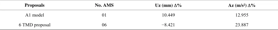
Table 7. Comparative results of displacements and accelerations.
Proposals No. AMS Uz (mm) % Az (m/s²) %
A1 model 01 10.449 12.955
6 TMD proposal 06 −8.421 23.887
A1 was the better alternative with a 10.449% displace- ment reduction and a 12.995% acceleration reduction. Despite presenting a greater acceleration reduction, model A2 presented displacement amplification.
Still considering a single TMD placed at the same node, a new set of parameters was attributed based on work of Santos [13] parametric studies of a 3D model considering beams and columns, similar to the present work structure. The parameter values adopted were α = 0.82, = 0.10 and = 0.4, as indicated on Table 5, where A3 is the model tuning the TMD on the first fre- quency and A4 the TMD tuned on the fourth frequency. The dynamic response in both cases is presented on Ta- ble 6.
It is verified that, as well as in the last proposal, a bet- ter performance with the TMD tuned on the first fre- quency presenting a 7.514% displacement reduction and a 9.881% acceleration reduction. Nevertheless, model A1 showed better performance.
Based on all presented results it can be concluded that the displacement reduction is better achieved tuning the TMD to the first frequency. In acceleration reduction the best performance happened when tuning the TMD to the fourth frequency, but in these cases an undesirable in- crease on displacements was observed. In this way, the best proposal to control the structure is model A1, using a single TMD tuned to the first natural frequency of the structure. A comparison between model A1 and the 6 TMD initial proposal is shown in Table 7. Model A1 was the more indicated design in a way that despite not reducing so well accelerations, no increase in displace-
ment is noticed. A displacement increase is not recom- mendable in a structural point of view.
6. Conclusion
This paper presents the study of the vibration problem of a commercial building floor used as a gym. The concrete slab analyzed presented excessive vibrations when sub- jected to typical exercise rhythmic loading. A control system was proposed using the Tuned Mass Damper de- vice. Also a parametric study to design the TMD was performed considering four different concrete slabs with varying dimensions, support conditions and loads. The control system showed to be effective reducing by 10% displacement amplitudes of the gym floor analyzed.
7. Acknowledgements
This work has been supported by CNPq and CAPES bra-zilian agencies which are gratefully acknowledged.
REFERENCES
[1] P. Dallard, A. I. Fitzpatrick, A. Flint, S. Le Bourva, A. Low, R. Smith and M. R. Willford, “The London Millen- nium Footbridge,” The Structural Engineer, Vol. 79, No. 22, 2001, pp. 17-33.
[2] I. Saidi, “Development of a Viscoelastic Tuned Mass Damper to Reduce Walking Induced Vibrations in Build- ing Floors,” Thesis of Doctor of Philosophy, Swinburne University of Technology, Melbourne, 2012.
sign and Construction,” RevistaIbracon de Estruturas e Materiais, Vol. 6, No. 1, 2013, pp. 55-74.
doi:10.1590/S1983-41952013000100004
[4] T. T. Soong, G. F. Dargush, “Passive Energy Dissipation in Structural Engineering,” John Wiley & Sons, Chiches- ter, 1997.
[5] W. D. Varela, “Modelo Teórico Experimental para Aná- lise de Vibrações Induzidas por Pessoas Caminhando Sobre Lajes de Edifícios,” Ph.D. Thesis, COPPE/UFRJ, Rio de Janeiro, 2004.
[6] D. V. F. Lima, “Controle de Vibrações Induzidas em uma Laje de Academia de Ginástica com a Utilização de Amortecedores de Massa Sintonizados,” Master Thesis, Universidade de Brasília, Brasília, 2007.
[7] M. Setareh, J. K. Ritchey, A. J. Baxter and T. M. Murray, “Pendulum Tuned Mass Dampers for Floor Vibration Con- troll,” Journal of Performance of Constructed Facilities,
ASCE, Vol. 20, No. 1, 2006, pp. 64-73. doi:10.1061/(ASCE)0887-3828(2006)20:1(64)
[8] M. Setareh, J. K. Ritchey, T. M. Murray, J. H. Koo and M. Ahmadian, “Semiactive Tuned Mass Dampers for Floor Vibration Control,” Journal of Structural Engineering,
ASCE, Vol. 133, 2007, pp. 242-250.
[9] W. D. Varela and R. C. Battista, “Control of Vibration
Induced by People Walking on Large Span Composite Floor Decks,” Engineering Structures, Vol. 33, No. 9, 2011, pp. 2485-2494.
doi:10.1016/j.engstruct.2011.04.021
[10] R. G. Faisca, “Caracterização de Cargas Dinâmicas Ge- radas por Atividades Humanas,” Ph.D. Thesis, COPPE/ UFRJ, Rio de Janeiro, 2003.
[11] S. M. Avila, “Controle Híbrido para Atenuação de Vibra- ções em Edifícios,” Ph.D. Thesis, Pontifícia Universidade Católica do Rio de Janeiro, Rio de Janeiro, 2002. [12] R. C. Battista and W. D. Varela, “Medidas Corretivas pa-
ra Vibrações de Painéis Contínuos de Lajes de Edi- fícios,” Proceedings of the 30th Jornadas Sul-Americanas de Engenharia Estrutural, Brasilia, 2002.
[13] M. D. S. Santos, “Análise Numérica Do Controle de Vibrações em Lajes de Edifícios Utilizando Amortece- dores de Massa Sintonizados,” Master Thesis, Univer- sidade de Brasília, Brasília, 2009.
[14] R. Jangid, “Optimum Multiple Tuned Mass Dampers for Base Excited Undamped System,” Earthquake Engineer- ing and Structural Dynamics, Vol. 28, No. 9, 1999, pp. 1041-1049.
![Figure 1. Structural system model with a TMD installed [4].](https://thumb-us.123doks.com/thumbv2/123dok_us/7794691.727611/2.595.357.476.87.226/figure-structural-model-tmd-installed.webp)
![Figure 2well detailed on the work of Santos [13]. Numerical](https://thumb-us.123doks.com/thumbv2/123dok_us/7794691.727611/3.595.132.468.82.346/figure-well-detailed-work-santos-numerical.webp)