© 2017, IRJET | Impact Factor value: 5.181 | ISO 9001:2008 Certified Journal | Page 3527
BEHAVIOR OF FRAMED STRUCTURE SUBJECTED TO EXPLOSION ON
THE GROUND
Ganavi S
1, P S Ramesh
2, Dr V Devaraj
3, Yogish C B
41
Postgraduate Student, Department of Civil Engineering, SJBIT, Karnataka, India
2
Associate Professor, Department of Civil Engineering, SJBIT, Karnataka, India
3
Professor, Department of Civil Engineering, UVCE, Karnataka, India
4
Research Scholar, Bangalore University, Karnataka, India
---***---Abstract -
The threat of terrorist activity is a rising problem all over the globe from past few decades. The buildings are generally not designed to resists the explosive loads and these loads causes disastrous damage to structural members or results in collapse of buildings. Thus, it is essential to understand the performance of structures under explosive load. In the present work, a RCC building of G+4storey subjected to RDX explosive of 100kg is considered for the study. The positive phase parameters of explosive load of various standoff distances are determined as per UFC 3-340-02. The linear static analysis is performed using ETABS 2015. The response of the building is determined in terms of storey drift, column and beam forces and displacement of the building. The structure was found to be critical when the source of blast is nearer to the building. The structure is safe at 80m standoff distance.Keywords: Explosive load, RDX explosive, Standoff distance, Etabs 2015
1. INTRODUCTION
The term blast is usually used to depict any circumstance where an enormous amount of energy is released from a nuclear or chemical or mechanical source. However, from the perspective of the impacts of blast load upon structural frame systems, there exists a set of basic attributes which must be characterized and considered without depending on the type of source. Blasts happening in metropolitan cities nearer to the buildings may causes massive damage to the structure and adjoining structures and may result in loss of life. Such impacts causes immediate effects such as propagation of blast overpressures through the surrounding air, failure of cladding units and generates ground shock waves resulted due to interaction of energy released with the ground. Thus, significant attention has been given to protect structures in metropolitan urban communities because occurrence of explosion (Bombs, trinitrotoluene TNT, and so forth.,) inside and around the structures can cause disastrous effects on the integrity of the structure such as collapse of walls, failure of cladding units, damage to internal and external members. Also, occupants may suffer from injuries or loss of life may occur due to collapse of structure.
Due to various accidental or deliberate events, the behavior of structures subjected to blast load has been the subject of interest in recent years. Regular structures are constructed uniquely in contrast to the military structures and thus, these structures are found to be more vulnerable against blast loads. Traditional structures, mainly those above the ground are generally not designed to withstand the blast loads. Since, the magnitude of design loads is considerably lesser than those produced by most explosions, traditional structures are more liable to damage caused due to explosions. As a result the engineers are in search of solutions for the problem of blast situations in order to protect the life of people and the integrity of structures. Thus, in order to design blast resistant buildings, it is important to understand the behavior of building under blast load and its effects.
© 2017, IRJET | Impact Factor value: 5.181 | ISO 9001:2008 Certified Journal | Page 3528 the concentric braced building was found to have high
resistance against blast load compared to other buildings. P. Vinothini et.al [8] carried out the dynamic analysis of high rise building (10storey) subjected to two different blast load of 30kg and 60kg with source of blast considered at three different points from 10m to 15m using SAP2000. It was reported that the vibration produced during explosion and displacement were found to increases with increase in charge weight and decreases with increase in standoff distance. Thus, it was concluded that the effect of blast load was more when the magnitude of blast load is more.
In India, most of the buildings are low rise (H/D less than 1.5) in nature. The effect of explosion on such buildings is more compared to high rise (H/D greater than 3) buildings. This is because the distance between the source point and corresponding storey is less. Thus, in present study, the behavior of low raised RCC frame structure subjected to explosive (RDX) of 100kg detonated on ground is evaluated by linear analysis using ETABS 2015.
2. EXPLOSION AND BLAST WAVES
A chemical response that occurs with rapid release of enormous amount of hot gases and vitality is known as explosion. The explosion occurs within few moments releasing hot gases which results in producing very high pressure and temperature. The hot gases discharged during the blast will proliferate through the encompassing space in the form of waves. In addition to these hot gases discharged, the air around the encompassing volume where explosion has occurred will spread and the air molecules will ascend and subsequently there will be generation of waves known as explosion or blast wave. The blast wave includes the vitality produced during detonation and these waves propagate at speed higher than the sound.
3. CLASSIFICATION OF EXPLOSION LOADS
The different types of blast load available and load produced by them are as shown in table 1 [5]
Table -1: Loads produced by different types of explosion loads
4. INTERACTION OF BLAST WAVE WITH
STRUCTURE
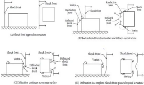
[image:2.595.307.555.212.358.2]During a blast, the impact wave created will spread through the encompassing air and subsequently results in the formation of shock or front wave (the contours formed by waves are assumed to be invariable). These waves will encompass the whole structure which gets refracted and diffracted.
Figure -1: Building and shock wave interaction
Figure 1 demonstrates the pictorial portrayal of shock wave interaction with structures. During explosion, the building is subjected to blast pressure (reflected and overpressure) and actions (drag forces) due to introduction of primary waves which result in formation of vortex which are unpredictable in nature. During refraction, the blast load acts normal to the surface exposed to explosion. Here, the structure deflects towards the right when the pressure acts on the left side of the structure and then the structure deflects slightly towards the left as the refraction of the pressure ends. The drag forces exerted on the structure will push the structure from the left side. Later these waves pass over the structure which results in development of forces known as suction forces. Finally, the amplitude of pressure decreases as the time elapses.
5. METHODOLOGY
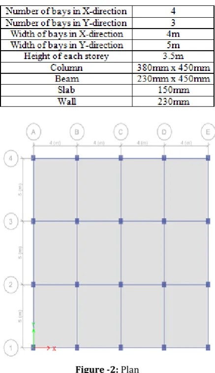
In the present work, a five storey RCC building having a base dimension of 16m x 15m is considered. Table 2 and table 3 represent the description of the model and material properties considered. The plan of the building considered for the analysis is shown in figure 2.
© 2017, IRJET | Impact Factor value: 5.181 | ISO 9001:2008 Certified Journal | Page 3529
Table -3: Description of the model
Figure -2: Plan
The building subjected to an explosive of RDX of 100kg weight detonated at various distance from 10m to 80m was analyzed using ETABS 2015. Here, the blast load is applied as a point load and linear equivalent static analysis is carried out.
6. COMPUTATION OF BLAST WAVE PARAMETERS
A RDX explosive of 100kg weight is considered for the study. The source of blast is considered at a distance of 10m, 15m, 20m, 25m, 30m, 50m, 60m, 70m, 75m and 80m. The various parameters of blast wave are obtained from the chart shown in figure 3.
Figure -3: Parameters of surface blast (positive phase) Source: UFC 3-340-02 (2008) [7]
The parameters of blast at various standoff distance are computed as per UFC 3-340-02, 2008 {page 90} and tabulated as shown in table 4. Table 5 indicates the pressure and joint load acting on the surface of the structure for various standoff distances from 10m to 80m. Figure 4 represents the 3-D view of the building with the blast load (static point load) at joints for the distance of 10m.
[image:3.595.52.271.111.490.2]© 2017, IRJET | Impact Factor value: 5.181 | ISO 9001:2008 Certified Journal | Page 3530
[image:4.595.323.544.130.506.2]Table -5: Blast load acting at different joint
Figure -4: Blast load for the case of standoff distance at 10m
7. RESULTS AND DISCUSSIONS
5 10 15 20 25 30 35 40 45 50 55 60 65 70 75 80 0
50 100 150 200 250
P
re
ss
u
re
,
k
N/m
2
Standoff Distance, m
Figure -5: Pressure versus standoff distance
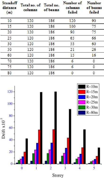
Table -6: Number of members failed
0 1 2 3 4 5
0 20 40 60 80 100 120
Dr
ift x10
-3
Storey
[image:4.595.324.544.539.716.2]R=10m R=15m R=20m R=25m R=30m R=80m
Figure -6: Drift of the storey for various distances
0 1 2 3 4 5
0 200 400 600 800 1000 1200 1400 1600
Displ
ac
eme
nt
(mm)
Storey R=10m
R=15m R=20m R=25m R=30m R=80m
© 2017, IRJET | Impact Factor value: 5.181 | ISO 9001:2008 Certified Journal | Page 3531
0 1 2 3 4 5
[image:5.595.52.560.47.809.2]0 1000 2000 3000 4000 5000 6000 7000 8000 Axia l l oa d (kN ) Storey R=10m R=15m R=20m R=25m R=30m R=80m
Figure -8: Axial load of column for various distances
0 1 2 3 4 5
0 1000 2000 3000 4000 5000 B ending M ome nt (kN-m) Storey R=10m R=15m R=20m R=25m R=30m R=80m
Figure -9: Bending moment of column for various distances
0 1 2 3 4 5
0 200 400 600 800 1000 1200 1400 1600 1800 2000 S he a r F or c e (kN ) Storey R=10m R=15m R=20m R=25m R=30m R=80m
Figure -10: Shear force of beams for various distances
0 1 2 3 4 5
[image:5.595.57.271.94.288.2]0 500 1000 1500 2000 2500 3000 3500 4000 4500 B ending M ome nt (kN-m) Storey R=10m R=15m R=20m R=25m R=30m R=80m
Figure -11: Bending moment of beams for various distances
From figure 5, it is observed that the amplitude of pressure generated during explosion decreases as the standoff distance increases. Thus, the pressure acting on the building reduces as the distance increases. When the explosion takes at a distance of 80m the low rise structure is found to be safe against blast load, where no failure of members will occur as presented in table6.
In figure 6 and 7, the drift and displacement of the building are presented for different standoff distance. It is observed that as the standoff distance increases, the drift and displacement decreases. These values are found to be high when the explosion occurs at 10m.
Figure 8 to figure 11 shows the axial loads on columns, bending moment variation in columns, Shear force and bending moment in beams when exposed to explosion at various standoff distances. The bending moment, axial load and shear force are found to be very high when the explosion occurs nearest to the building and vice versa. Thus, standoff distance is one of the significant factors which influence the effect of detonation.
8. CONCLUSIONS
In the present work, a G+4 storey RCC building subjected to blast load of 100kg at various standoff distances from 10m to 80m was analyzed using ETABS. Based on the results of linear equivalent static analysis, following conclusions were made:
i. The pressure is high when the source of blast (detonation) is nearer to the building and reduces as the source of blast is away from the structure. ii. The pressure varies inversely with standoff
distance.
iii. Storey drift and displacement decreases when the point of detonation is far away from the building. iv. Storey drift decreases as the height of the building
increases.
[image:5.595.49.275.331.517.2]© 2017, IRJET | Impact Factor value: 5.181 | ISO 9001:2008 Certified Journal | Page 3532 versa. Also, beam forces (shear force and bending
moment) decreases as the standoff distance increases.
vi. Storey drift and displacement are found to be within safe permissible limit, when the source of blast is at 80m. Thus, the safe attenuation point is at 80m for the chosen model.
REFERENCES
[1] Amy Coffield, Hojjat Adeli (2014) - An Investigation of the Effectiveness of the Framing Systems in Steel Structures Subjected to Blast Loading - Journal of Civil Engineering and Management, ISSN 1392-3730, 20(6), pp. 767-777.
[2] IS 4991-1968, Indian Standard: Criteria for Blast Resistant Design of Structures for Explosions above Ground, Bureau of Indian Standards, New Delhi, India.
[3] Jayashree S M, Helen Santhi M, Rakul Bharatwaj R (2013)– Dynamic response of a space framed structure subjected to blast load - International Journal of Civil and Structural Engineering, ISSN: 0976-4399, 4(1), pp. 98-105. [4] Jayatilake I N, Dias W P S, Jayasinghe M T R and Thambiratnam D P (2010) - Response of Tall Buildings with symmetric Setbacks under Blast loading – Journal of National Science Foundation, Sri Lanka, 38(2): pp. 115-123.
[5] Nasim Uddin (2010) – Blast protection of Civil Infrastructures and Vehicles using Composites – Woodhead Publishing Limited, Oxford Cambridge, New Delhi.
[6] Quazi Kashif, Dr. M B Varma (2014) – Effect of Blast on G+4 RCC Frame Structure – International Journal of Emerging Technology and Advanced Engineering, ISSN: 2250-2459, 4(11), pp. 145-149.
[7] Unified Facilities Criteria (UFC)-3-340-02 (2008), Structures to Resists the Effects of Accidental Explosions, U S Army Corps of Engineers, Naval Facilities Engineering Command, Air Force Civil Engineer Support Agency. [8] Vinothini P, Elavenil S (2016) - Analytical Investigation of High Rise Building under Blast loading – Indian Jounal of Science and Technology, ISSN: 0974-5645, volume 9(18), pp. 1-7.
ACKNOWLEDGEMENTS
The authors sincerely thank former Professor and Head Prof. Prasad CSMV, Professor and Head Prof. Narendra Kumar H, Department of Civil Engineering, and Dr. Puttaraju, Principal, SJB Institute of Technology, Bengaluru for their encouragement and for providing facilities to carry out this research work as a part of M.Tech project.
BIOGRAPHIES
Ganavi S
Postgraduate student, Structural Engineering,
Department of Civil Engineering, SJBIT, Bangalore -560060, Karnataka, India.
P S Ramesh
Associate Professor,
Department of Civil Engineering, SJBIT, Bangalore -560060, Karnataka, India.
Dr. V Devaraj Professor,
Department of Civil Engineering, UVCE, Bangalore -560056, Karnataka, India.
Yogish C B Research Scholar, Bangalore University,