© 2017, IRJET | Impact Factor value: 5.181 | ISO 9001:2008 Certified Journal | Page 1875
Smart Car
Ajay Shetgaonkar
1, Tanay Shirodkar
2, Rohit Yadavade
3, Suneeta Raykar
41
BE, Dept of Electrical and Electronic Engineering, Goa College of Engineering,Goa,India
2BE, Dept of Electrical and Electronic Engineering, Goa College of Engineering,Goa,India
3BE, Dept of Electrical and Electronic Engineering, Goa College of Engineering,Goa,India
4
Associate professor, Dept of Electrical and Electronic Engineering, Goa College of Engineering,Goa,India
Abstract- Travelling is a part of our daily life and we
spend a considerable amount of resources on it. But it is not a pleasant experience every time. We face problems such as road blocks, accidents caused by human errors, & some due to un-highlighted speed breakers & pot holes. Sometimes, traffic can be brought to halt by inappropriate parking on narrow roads. Also there exists a possibility of theft of the parked vehicles.
This paper will discuss four features of a smart car using Arduino MEGA 2560 Microcontroller.
Key Words -
Android application, GSM SIM900A, GPS, Arduino Mega, Ultrasonic sensors, sound sensor, Proximity sensor, RF module.1. INTRODUCTION
With increase in traffic density, we face many problems while travelling such as:
1. Road blocks due to vehicles parked
inappropriately on the road.
2. Pot holes, speed breakers and vertical
obstructions on the road.
3. Lack of guidance during parking of the vehicle or
travelling on a narrow road
4. Theft of the vehicle.
Speed-breakers are traffic calming devices commonly installed to reduce speed of vehicles but, it is well known to us that speed breakers can cause accidents and injury. When a vehicle approaches a speed-breaker at a high speed, if the speed breaker is not visible the risk of accident or injury is substantial. Speed-breakers are inconspicuous in low visibility conditions, like at night, or when there is fog, rain or snow or if they aren’t preceded by proper warning signs.
A pot hole is a type of failure in an asphalt pavement, caused by the presence of water in the underlying soil structure and the presence of traffic passing over the affected area. Pot holes are also known to cause accidents in some cases & may damage the vehicles over the period of time. Also, it causes great discomfort while you are travelling.
At times we need assistance while parking and while travelling on narrow roads. Making way through congested paths is a hectic and stressful task. The fear of damage being caused to the vehicles is prominent. While some problems are inevitable, the few stated above can be solved with proper anticipation & technology.
2
.RELATED WORK
Gummarekula Sattibabu et.al[1] proposed a method of detecting a speed breaker. They used a RF module and ARM microcontroller to detect speed breakers by placing RF module on the sign board and at the vehicle’s dashboard. If the vehicle is in that zone then it will display a message on LCD with buzzer. Rajeshwari Madli et.al[2] proposed a method of detecting potholes. They used an ultrasonic sensor which is used to detect potholes and send the information to the server via GSM and GPS module which will then send the information to the owner phone. Bhoraskar et.al[3] proposed a method for detecting vehicle braking and road bumps. They used machine learning techniques to detect road anomalies
and braking events from accelerometer and
magnetometer data. The method will not always work because magnetometer is not present in all phones, is susceptible to magnetic interference and increases battery consumption. In addition, the performance of this algorithm was not evaluated for various different types of speed-breakers, vehicles and drivers.
Mohan P. et al [7] proposed a method for detecting speed bumps and braking events. This work did not differentiate between potholes and speed-breakers, and labelled them both as speed bumps. Just like [3] requires magnetometer for reorientation, [7] requires GPS for reorientation, increasing overall complexity and battery consumption. Recently, mobile phone crowd-sourcing based pothole detection has also gained significant attention [5]. In this work [5], the mobile phone had to be placed a certain way on the dashboard to avoid reorientation complexity.
© 2017, IRJET | Impact Factor value: 5.181 | ISO 9001:2008 Certified Journal | Page 1876
because of the difference in overall sensitivity tovariations
along vehicle’s z-axis. Another approach was proposed in [4]. They used an early warning system that uses a smartphone based application to alert the driver in advance when the vehicle is approaching a speed breaker. In addition, the application constantly monitors the smartphone accelerometer to detect previously unknown speed-breakers and it doesn’t have to accelerometer reorientation.
3. COMPONENTS USED
3.1 Arduino MEGA 2560
The MEGA 2560 is a microcontroller board based on the ATmega2560. It has 54 digital input /output pins (of which 15 can be used as PWM outputs), 16 analog inputs, a 16 MHz crystal oscillator, a USB connection, flash memory of 256 kB, operating voltage of 5V,operating current in a range of 20mA-50mA and a power jack.
3.2 Ultrasonic sensors (HC-SR04
):
The ultrasonic module has 2 transducers, one for transmit & other for receive. Both are fixed on a single PCB with control circuit. Ultrasonic distance sensor provides precise, on-contact distance measurements from about 2cm-200cm.
The ultrasonic module will send out an 8 cycle burst of ultrasound at 40 KHz and raise its echo line high. It then listens for an echo and as soon as it detects one it lowers the echo line again. The echo line is therefore a pulse whose width is proportional to the distance to the object if nothing is detected then the module will lower its echo line anyway after 30ms.
3.3 Sound impact sensor:
It uses a small microphone and amplifier to detect sound. When the loudness (dB level) of the sound exceeds a preset level, the output of the sensor goes from low (0V) to high (5V).
A small trimmer control lets you adjust the sensitivity of the sensor. Setting this control has the effect of increasing or decreasing the effective range of sensor, & its overall sensitivity to sound levels.
3.4 GSM SIM 900A Shield:
The GSM Shield allows the Arduino to connect to the internet, make / receive voice calls and send/receive SMS messages.
To interface with the cellular network the board requires a SIM card provided by a network operator. GSM Shield for arduino is based on SIM900A Dual band GSM/GPRS module.SIM900A is a GSM/GPRS designed with a very powerful single-chip processor integrating AMR926EJ-S core. It is configured and controlled via its UART using simple AT commands.
SPECIFICATIONS:
Voltage Range:6V-12V
Current Range: Standby: 8 mA | Ideal:
60mA|Transmission: 180mA|Reception:
320mA|Peak: 2000Ma
Baud rate: 9600 b/s
3.5 LCD:
Liquid crystal display screen is an electronic display module. A 16x2 LCD can display 16 characters per line and we can have two such lines.
This LCD has 2 registers, namely, command & data. Command register stores the command instructions given to the LCD while data registers stores the data to be displayed.
3.6 RF Module:
The RF Module operates at radio frequency (30 KHz – 300 GHz).The digital data is represented as variations in the amplitude of the carrier wave. This kind of modulation is known as Amplitude Shift Keying. The RF Module comprises of an RF Transmitter and a RF Receiver. The Transmitter/Receiver pair operates at a frequency of 434 MHz. A RF Transmitter receives serial data and transmits it wirelessly through its antenna. The Transmitted data is received by an RF Receiver operating at the same frequency as that of the Transmitter. The RF Module is often used along with a pair of encoder/decoder. The encoder is used for encoding parallel data for transmission feed while reception is decoded by a decoder. Since most of the
encoders/decoders/microcontrollers are TTL
© 2017, IRJET | Impact Factor value: 5.181 | ISO 9001:2008 Certified Journal | Page 1877
microcontroller. This serial data can be directly readusing the RF Transmitter, which then performs ASK modulation on it & transmits the data through the antenna. The RF Receiver receives the modulated signal through the antenna, performs all kinds of processing (filtering, demodulation, etc.) and gives out a serial data. This serial data is then converted to a TTL level logic data which is same data that the user has input.
3.4.1 Serial encoder/decoder:
The HT12E Encoder IC’s are capable of Encoding 12bit of information which consists of N address bits and 12-N data bits.
The HT12D Decoder IC’s receive the serial address and data from its corresponding encoder, transmitted by a carrier using an RF transmission medium and gives output to the output pins after processing the data.
3.7 GPS :
The SkyNav SKM53 Series with embedded GPS antenna
enables high performance navigation in the most stringent applications and solid fix even in harsh GPS visibility environments.
It is based on the high performance features of the MediaTek 3329 single-chip architecture, its –165dBm tracking sensitivity extends positioning coverage into place like urban canyons and dense foliage environment
where the GPS was not possible before. The 6-pin UART
connector design is the easiest and convenient solution to be embedded in a portable device and receiver like
PND, GPS mouse, car holder, personal locator, speed
camera detector and vehicle locator.
3.8 IR sensor
:The IR Sensor-Single is a general purpose proximity sensor. Here we use it for collision detection. The module consists of an IR emitter and IR receiver pair. The high precision IR receiver always detects an IR signal.
The module consists of 358 comparator IC. The output of sensor is high whenever it IR frequency and low otherwise. The on-board LED indicator helps user to check status of the sensor without using any additional hardware. The power consumption of this module is low. It gives a digital output.
4. ARCHITECTURE AND IMPLEMENTATION
The architecture consists of three sections, namely, input section, processing unit and output section. The input section collects the information from various sensors and sends the received signals to the microcontroller. The microcontroller processes it and sends the processed signals to the output section. The output section displays the processed data.
4.1 Input section:
It consists of 4 sensors, i.e., ultrasonic sensor, GPS receiver, sound sensor and IR sensor.
© 2017, IRJET | Impact Factor value: 5.181 | ISO 9001:2008 Certified Journal | Page 1878
4.2 Processing unit:
Microcontroller ATmega2560
Operating Voltage 5V
Input Voltage
(recommended) 7-12V
Input Voltage (limit) 6-20V
Digital I/O Pins 54 (of which 15 provide PWM output)
Analog Input Pins 16
DC Current per I/O
Pin 20 mA
DC Current for 3.3V
Pin 50 mA
Flash Memory 256 KB of which 8 KB used by bootloader
SRAM 8 KB
EEPROM 4 KB
Clock Speed 16 MHz
Length 101.52 mm
Width 53.3 mm
Weight 37 g
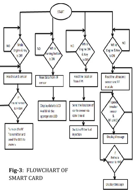
There are four loops present in the ATmega2560 microcontroller, namely, loop 1, loop 2, loop 3 and loop 4 that stands for loop of speed breaker and pothole detection, parking guidance, parking chaos and anti-theft respectively.
Loop 1 runs when the engine is on and the true key is inserted. Loop 2 lies within loop 1. It runs only when the parking mode is activated. Loop 3 runs only when the engine is off and the true key is removed. Loop 4 runs when the engine is turned on but the true key is absent.
4.3 Output section:
The output section consists of 4 major components, i.e., GSM shield, LCD, LED and buzzer.
The GSM shield has a registered SIM card. When the loop for parking chaos is run, a message is sent to the
owner’s number, which is memory of the
microcontroller via a mobile network. Also, when loop for anti-theft is run, the GSM shield will send the coordinates of the location of the card to the owners number.
The LCD panel will display the distance between the cars bonnet and the incoming speed breaker and/or pothole. It will also flash a message when the distance decreases beyond the threshold value for the speed breaker and increases beyond the threshold for a pot hole.
The buzzer will sound an alarm when the distance of speed breaker (and/or pothole) increases (or decreases) from the set threshold value.
The LED will give parking guidelines by blinking when the distance between the car and the obstacle decreases beyond a set threshold value.
Fig-1: BLOCK DIAGRAM
© 2017, IRJET | Impact Factor value: 5.181 | ISO 9001:2008 Certified Journal | Page 1879
5. EXPERIMENTAL RESULTS
It was tested in a simulated environment with artificial potholes and speed breaker, traffic block, parking assist and theft.
Speed breaker detection was conducted in two phases. Initially when the speed breaker was at a distance exceeding 80cm, RF transmitter and receiver were used for speed breaker detection since the range of the ultrasonic sensor is only less than 80cm. When a speed breaker was detected, the buzzer beeped and the LCD displayed a message saying “speed breaker is coming up”. At this point, the RF receiver was turned off to avoid a repeated notification from the same speed breaker. Once this detected speed breaker came within a range of 80cm, the ultrasonic sensor detected the exact distance of the speed breaker from the vehicle which was displayed on the LCD and simultaneously buzzer was sounded.
Fig 4: PROTOTYPE IMPLEMENTATION
[image:5.595.44.274.96.421.2]For the pot holes detection, the cut-off distance was in the range of 15 to 30 cm, if pot hole was detected within this distance, the LCD displayed a message and buzzer sounded.
Fig-5 : SPEED BREAKER DETECTION
[image:5.595.339.535.97.236.2]In case of traffic chaos, if a high pitch noise was detected for certain duration of time, the RF transmitter in prototype would send a signal which was captured by the key chain of the owner. It would also send a SMS to owner’s cell phone via the GSM shield.
Fig-6: CAR KEY CHAIN MODEL Fig-3: FLOWCHART OF
[image:5.595.333.542.331.447.2] [image:5.595.334.542.550.705.2]© 2017, IRJET | Impact Factor value: 5.181 | ISO 9001:2008 Certified Journal | Page 1880
Fig-7: MESSAGE FROM GSM SHEILD TO MOBILEFor parking assistance, there is a key called parking key in the prototype for the assist function. By turning it on, it will help driver by blinking the LED on the appropriate side i.e. left and/or right. A threshold of 2cm was set. When the distance between the car corner and the obstacle is reduced below the 2cm, the respective LED glows. Buzzer would also sound at this point.
For theft , if the engine was turned on but the key was missing then the GPS would note the location and send a SMS to the owner via the GSM shield . Also, the fuel injection would be turned off until the key is inserted.
6. CONCLUSION AND FUTURE WORK
In this paper the prototype design of a smart car that can detect humps, potholes and theft, help deal with traffic chaos and provide parking assistance. It is very simple, durable and low in cost. It consumes less power and can be applied in the real world. It can work in bad weather condition too. Overall, such a car will eliminate the major issues encountered and hence make driving a pleasant experience.
Since, RF signal get blocked or get attenuate if more than one transmitter is there which can be reduced by changing the frequency of RF for different set of units. Here the sensible distance by ultrasonic sensor is less i.e. 3 meter for both pot and speed breaker, so it can be further increase by using laser finder sensor whose range is more the 1 km.
Traffic chaos assists can be more improved by using camera interface with Arduino.
REFERENCES
[1] Gummarekula Sattibabu,, B.V.V.Satyanarayan, VV Satyanarayana Kona: Automatic Vehicle Speed Control With Wireless In-Vehicle Road Sign Delivery System Using ARM 7, INTERNATIONAL JOURNAL OF TECHNOLOGY ENHANCEMENTS AND EMERGING ENGINEERING RESEARCH, VOL 2, ISSUE 8 32 ISSN 2347-4289
[2] Rajeshwari Madli, Santosh Hebbar, Praveenraj Pattar, G.V.Prasad: Automatic Detection and Notification of Potholes and Humps on Roads to Aid Drivers, DOI 10.1109/JSEN.2015.2417579, IEEE Sensors Journal
[3] BHORASKAR, R., VANKADHARA, N., RAMAN, B., AND Fig-10: Message from GSM Shield to mobile
phone in theft case
© 2017, IRJET | Impact Factor value: 5.181 | ISO 9001:2008 Certified Journal | Page 1881
KULKARNI, P. Wolverine: Traffic and road conditionestimation using smartphone sensors. In Communication Systems and Networks (COMSNETS), 2012 Fourth International Conference on (jan. 2012), pp. 1 –6.
[4] MOHIT JAIN, AJEET PAL SINGH, SOSHANT BALI, SANJIT KAUL: Speed-Breaker Early Warning System.
[5] ERIKSSON, J., GIROD, L., HULL, B., NEWTON, R., MADDEN, S., AND BALAKRISHNAN, H. The Pothole Patrol: Using a Mobile Sensor Network for Road Surface Monitoring. In The Sixth Annual International conference on Mobile Systems, Applications and Services (MobiSys 2008) (Breckenridge, U.S.A., June 2008).
[6] MEDNIS, A., STRAZDINS, G., ZVIEDRIS, R., KANONIRS, G., AND SELAVO, L. Real time pothole detection using android smartphones with accelerometers. Distributed Computing in Sensor Systems and Workshops, International Conference on 0 (2011), 1–6.
[7] MOHAN, P., PADMANABHAN, V. N., AND RAMJEE, R. Nericell: rich monitoring of road and traffic conditions using mobile smartphones. In Proceedings of the 6th ACM conference on Embedded network sensor systems (New York, NY, USA, 2008), SenSys ’08, ACM, pp. 323– 336.