© 2018, IRJET | Impact Factor value: 6.171 | ISO 9001:2008 Certified Journal | Page 2179
Optimization of Design and Analysis of Y-Axis Spindle for SB CNC-30
Machine
Prof. Issac Thamban
1, Bessy Paul
2, Vysakh R Nair
3, Peter Siby
4, Cijo Saju
5,Sanal P P
61Professor,Department of Mechanical Engineering, Mar Athanasius College of Engineering, Kerala, India. 2Deputy Engineer, Design Section, Hindustan Machine Tools Ltd, Kalamassery, Kerala, India.
3,4,5,6Department of Mechanical Engineering, Mar Athanasius College of Engineering, Kerala, India.
---***---Abstract –
Spindles are used to provide a relative motionbetween the work piece and the tool. Usually when the spindles are designed its dimensions may not be optimized. This may result in greater vibration and induction of stress which results in poor machining accuracy.
The project aims to optimise the existing y-axis spindle design of SB CNC 30 machine so as to achieve improved accuracy of rotation for a prescribed rigidity of spindle unit. This also includes determination of critical speed and strength of the spindle. This project deals with optimisation of outer spindle diameter and span length between the bearings ensuring maximum static and dynamic stiffness and minimum deflection.
Key Words: Spindle, SB CNC 30 machine, static stiffness, optimization, modal analysis, Von-Mises stress.
1. INTRODUCTION
A machine tool is composed of basic components: spindle, moving axes and a cutting tool. Among these components, spindle is almost the most critical one due to its vital duty in the metal cutting process.The basic purpose of spindle is rotating either the workpiece or the cutter with enough torque and speed against the other which is fixed to enable the cutting happen. An internal driven motor is used to provide the required drive to the spindle. Such spindles have built-in electric motors inside the housing coupled with the spindle shaft.
Because spindle shaft is the main rotating component of the system and one of the first component to withstand the loads during cutting, its stiffness and robustness greatly affect both static and dynamic behaviour of the spindle system and ultimately the performance of the machine. The basic spindle structure consists of housing, bearings, motor and a spindle shaft. The spindle structure and its components arrangement are shown in the figure 1.1. The bearings used in the design are angular contact ball bearings and cylindrical roller bearings due to its high radial load capacity, rigidity and low coefficient of friction.
In this research we are optimising the span length between the bearings and outer diameter of the spindle for a prescribed rigidity of the spindle unit and accuracy of spindle rotation. Optimization is done for the y-axis spindle of SB CNC 30 machine. SB refers to slant bed and CNC 30 refers to the model name. The research also extends to the determination of critical speed of the spindle.
The spindle is considered as a beam which is supported between the bearings with a net load acting at the overhanging section. This net load comprises of weight of chuck, weight of job, tangential and radial cutting forces.
Optimization is carried out so as to satisfy two conditions.
1. Minimum deflection at the overhanging section. 2. Maximum dynamic stiffness of the spindle.
Fig.1.1: Basic lathe spindle structure.
1.1 Assumptions Followed.
Some of the assumptions followed while designing the spindle are as follows.
(a) The test shaft is assumed to be Euler-Bernoulli beam. (b) Both the beam and bearings act according to Hooke’s
law.
(c) Any torsional and axial deflections of the shaft are neglected.
(d) Deflections and slopes are small.
(e) The bearing housings are assumed to have infinite stiffness.
(f) The contribution of transverse shear deformation to the overall lateral deflection is assumed to be negligible.
© 2018, IRJET | Impact Factor value: 6.171 | ISO 9001:2008 Certified Journal | Page 2180 1.2 Material Used.
The material used for spindle is C2R toughened steel (15Ni7Cr4Mo2) and its chemical composition is given below:
1.Carbon C(%) =0.15 2. Silicon Si(%)=0.23 3. Manganese Mn(%)=0.5 4. Phosphorous P(%)=0.040 5. Sulphur S(%)=0.040 6. Copper C(%)=0.025 7. Chromium Cr(%)=0.10 8. Nickel Ni(%)=0.011 9. Tin Sn(%)=0.05
The material attains its required toughness and hardness after a number of heat treatment processes like carburising, annealing, normalising, hardening and toughening. This is achieved by passing and dipping the spindle in carburising bath, hardening bath, annealing bath and quenching bath in the heat treatment section. Approximate contents in carburizing bath are sodium cyanide (8-10%), sodium chloride and barium chloride at working temperature of 9100C. Hardening bath (8500C) and annealing bath (6500C)
comprises of sodium chloride and barium chloride while quenching bath consist of sodium nitrite and sodium nitrate at a temperature of 1800C. Mechanical properties of C2R
toughened steel are shown in table 1.2.1.
Serial
Number. Mechanical Properties. Property Values.
1. Density. 7850 kg/m3
2. Hardness, Brinell. 155 HB 3. Ultimate Tensile Strength. 1079.1 MPa 4. Yield Strength. 588.6 MPa 5. Endurance Strength. 470.88 MPa 6. Modulus of Elasticity. 206 GPa 7. Poisson’s Ratio. 0.29
Table1.2.1: Mechanical properties of C2R toughened steel.
2. METHODOLOGY
The objective of this research is to optimize the span length between the bearings and outer diameter of the spindle for a prescribed rigidity of the spindle unit and accuracy of spindle rotation. The research also extends to the determination of critical speed of the spindle.
First design calculations for the spindle and bearings were carried out for optimizing the span length and outer diameter of spindle using CMT design handbook and bearing catalogues. Microsoft Excel sheet was used to carry out several iterations and to arrive at optimum results. Optimization was carried out so as to satisfy two conditions.
1. Minimum deflection at the overhanging section. 2. Maximum dynamic stiffness of the spindle.
Inner diameter of the spindle is kept constant throughout (d=103 mm) and outer diameter is varied. The spindle is considered as a beam which is supported between the bearings with a net load acting at the overhanging section. This net load comprises of weight of job, weight of chuck, tangential and cutting forces.
The spindle is then modeled using Creo Parametric 2.0. as shown in figure 2.1.
Fig.2.1: Spindle modeled using Creo Parametric 2.0.
The spindle is then analyzed both statically and dynamically The static analysis mainly focuses on the spindle deflection and stiffness in the loaded case, which is the worst-case machining scenario. The distances between the bearings, or the support locations on the spindle shaft, directly affect the spindle static stiffness, therefore in the static analyses, investigation and selection of optimum bearing spans within an applicable range is calculated analytically. These optimum values are used in the further analyses and the final design. And finally in the dynamic analysis, the modes, natural frequencies and the critical speeds of the design are investigated.
Static analysis was carried out using Finite Element Method (FEM) with the software ANSYS Workbench 16.0. Stress, strain and deflection of the spindle are determined using this method. Dynamic analysis was done using ANSYS Mechanical APDL 16.2.
2.1 Design calculations.
Load diagram is drawn by considering the spindle as a beam which is simply supported at two ends and a net load acting at the overhanging section. Here maximum load conditions are taken. Hence weight of job, Wjob = 200kgf and weight of
chuck, Wchuck = 50kgf.Tangential cutting forces were
© 2018, IRJET | Impact Factor value: 6.171 | ISO 9001:2008 Certified Journal | Page 2181 Fig.2.1.1: Load diagram of spindle bearing system.
RA and RB are the reactions exerted by cylindrical roller
bearing and angular contact ball bearings respectively.
Resolving forces in vertical direction,
RA+F = RB
RB – RA = 1036.4216 ... (i)
At equilibrium, ∑Mc = O
RA (318.99+154.55) – 154.55RB = 0
RB = 3.06399 RA ... (ii)
Solving (i) and (ii)
RA = 502.14468 kgf
RB = 1538.566 kgf
Inner spindle diameter and overhanging length are kept constant throughout as 103 mm and 154.55 mm respectively. Initially the span length between bearings is taken as 318.99 mm which needs to be optimized. The span length between the bearings and outer spindle diameter is to be optimized. A triple row angular contact ball bearing (front bearings) is mounted near the spindle nose and a double row cylindrical roller bearing (rear bearing) is mounted at the other end.
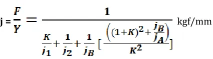
Spindle rigidity(j) is given by,
j = kgf/mm
where k = l/a is the ratio of span length (l) to overhanging
length (a), jA and jB are the rigidity of the cylindrical roller
bearing and angular contact ball bearing respectively and Y is the deflection at the overhanging section. Once spindle rigidity is determined, deflection can be determined using j=F/Y.
Bearings are designed using CMT design handbook and SKF bearing catalogues. Numerically optimum span length and optimum outer diameter of spindle are obtained by changing the distance between bearings and outer diameter of spindle simultaneously, so that deflection of the spindle at overhanging section is minimum and static stiffness is maximum. The number of rows of bearings are also changed
to arrive at optimum results. These iterations are done using Microsoft Excel.
The first critical speed of the shaft is given by,
Ncr = C rpm
Where I is the moment of inertia of spindle, l is the span
length and w=66.80486 kgf is the weight of the shaft, C is a
constant and is equal to 13.5x10⁵ for simply supported
beams.
2.2 Static analysis and optimization.
During machining, spindle experiences various loads due to cutting, centrifugal effects, etc. These loads may invoke self-excited vibrations and may cause spindle failure due to high deformation and high stresses generated. Therefore, the spindle design should be analyzed and verified statically and dynamically. The static analysis of the spindle basically deals with the spindle stiffness which is closely related to the load capacity and vibration resistance of the spindle. It also helps to analyze the accuracy loss during limit pushing cutting operations.
In this research, the preliminary spindle design is analyzed both statically and dynamically. The static analysis mainly focuses on the spindle deflection and stiffness in the loaded case, which represents the maximum load conditions. Static analysis is done in ANSYS Workbench 16.0 which includes determination of optimum span length and optimum outer diameter. Here the position of angular contact ball bearing is fixed and position of cylindrical roller bearing is changed along the spindle length. Deflection is analyzed at each position and span length corresponding to minimum deflection was chosen as the optimum span length. The results from static analysis are then compared with those obtained from numerical calculations.
2.3 Dynamic analysis
Every spindle experiences vibration due to the nature of cutting operation, but the severity of the vibration greatly influences the machining accuracy, the life of cutting tool and spindle, cutting power necessary for the operation. Thus, dynamic analysis is important to investigate and understand the spindle modal behavior.
© 2018, IRJET | Impact Factor value: 6.171 | ISO 9001:2008 Certified Journal | Page 2182 should always be avoided no matter what the source is,
spindle, cutting tool, fixture, etc. In modal analysis, the modes, natural frequencies and the critical speeds of the design are investigated.
3. RESULTS AND DISCUSSIONS.
In this work results from both numerical calculations and that obtained from FEA (Finite Element Analysis) method are compared so as to arrive at optimum results. Maximum static stiffness and minimum deflection at the overhanging section are satisfied during optimization. Thus stress induced in the spindle are minimum and within the yield limit. Hence spindle and bearing failure does not occur during machining.
3.1 Using design calculations.
The results obtained using numerical calculations are shown in the following table.
Sl.NO Parameters Before
Optimization After Optimization 1 Outer spindle
diameter 160 mm 180 mm
2 Span length
between bearings
318.99 mm 463.65 mm
3 Stiffness of
spindle 0.4114*10
9
N/m 0.785*10
9
N/m 4 Deflection at the
overhanging section
24.71 µm 12.9 µm
Table.3.1.1: Results of analytical method.
Thus by changing the outer spindle diameter from 160 to 180 mm and the span length from 318.99 mm to 463.65 mm stiffness of spindle increases and deflection at the overhanging section reduces. Thus optimum outer diameter is 180 mm and optimum span length is 463.65 mm.
3.2 Using FEA method
During machining, both in axial and lateral directions, cutting forces are generated on the spindle. However, in most cases, lateral loads are greater than the axial loads, and similarly the axial stiffness of the spindle is greater than the bending stiffness. Therefore, especially for lathe spindles, it is more important to investigate the lateral loading of the spindle in the static analysis. In this research, only lateral deflection and bending stiffness are studied and calculated.
Structural analysis was carried out using FEA method with the software ANSYS Workbench 16.0. Stress, strain and deflection of the spindle are determined using this method. This method involves dividing the entire structure into smaller elements of finite dimensions which are connected
[image:4.595.38.289.315.489.2]together at finite number of joints called nodes. This process is called mesh formation. The results of analysis before optimization are shown in following figures.
Fig.3.2.1: Variation of shear stress before optimization.
[image:4.595.312.556.324.490.2]Fig.3.2.2:Variation of total deformation before optimization
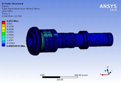
Fig.3.2.3:Variation of Von-Mises stress before optimization.
[image:4.595.311.558.535.710.2]© 2018, IRJET | Impact Factor value: 6.171 | ISO 9001:2008 Certified Journal | Page 2183 Fig.3.2.4: Variation of total deformation after optimization
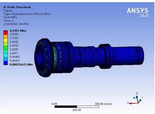
Fig.3.2.5:Variation of Von-Mises stress after optimization
Fig.3.2.6:Variation of shear stress after optimization.
The results from structural analysis shows that maximum deformation occurs at the overhanging section where the net load is acting. The results obtained using FEA method are shown in table.3.2.1
Sl.NO Parameters Before
optimization After optimization
1 Outer spindle
diameter 160 mm 170 mm
2 Span length
between bearings 318.99 mm 386.47 mm 3 Stiffness of spindle 3.829*109
N/m 4.8186*10
9
N/m 4 Deflection at the
overhanging section
2.655 µm 2.11 µm
5 Maximum
equivalent stress 6.652 MPa 4.3411 MPa
Table.3.2.1: Results of FEA method.
Thus using FEA method, optimum outer diameter is 170 mm and optimum span length is 386.47 mm. The spindle shaft only experiences elastic deformation under the cutting forces studied. As shown in figure.3.2.5, the maximum von-Mises stresses generated in the shaft are at the bearing locations and have the value of 4.34 MPa, which is fairly below 588.6 MPa, the yield strength of C2R steel-spindle shaft material. Therefore, the shaft is sufficient to carry the loads without any plastic deformation or failure and no plastic deformation is expected during cutting operations.
There are variation in the values obtained using FEA method and analytical method. However for both the cases, bearing span length directly affects the static stiffness of spindle. The deviation in the values may be due to the assumptions followed for the analytical method. The analytical model is still found useful for the optimization of bearing spans and understanding the behavior of spindle rigidity. However for better estimations of the deflection and rigidity, FEM solution and results should be used.
Optimization of spindle design also results in improved accuracy of rotation with high dynamic stiffness and minimum deflection. Thus machining accuracy can be improved.
3.3 Modal analysis
The dynamic analysis of the preliminary spindle design is done using ANSYS Mechanical APDL 16.2. The analysis is performed with the same simplified spindle model used in the static FEM analyses. The eigen frequencies of the spindle calculated for the first 10 modes and the corresponding speeds in rpm are given in table .3.3.1.
Modes Frequency (Hz) Speed (Rpm) 1st 12.5893 755.358
2nd 12.6187 757.122
3rd 19.9369 1196.214
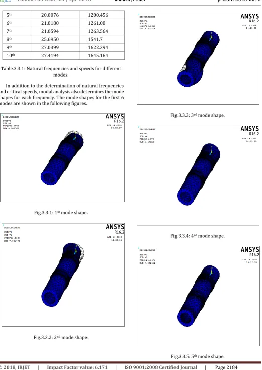
[image:5.595.40.285.495.658.2]© 2018, IRJET | Impact Factor value: 6.171 | ISO 9001:2008 Certified Journal | Page 2184 5th 20.0076 1200.456
6th 21.0180 1261.08
7th 21.0594 1263.564
8th 25.6950 1541.7
9th 27.0399 1622.394
10th 27.4194 1645.164
Table.3.3.1: Natural frequencies and speeds for different modes.
In addition to the determination of natural frequencies and critical speeds, modal analysis also determines the mode shapes for each frequency. The mode shapes for the first 6 modes are shown in the following figures.
Fig.3.3.1: 1st mode shape.
Fig.3.3.2: 2nd mode shape.
Fig.3.3.3: 3rd mode shape.
[image:6.595.40.562.58.793.2]Fig.3.3.4: 4rd mode shape.
© 2018, IRJET | Impact Factor value: 6.171 | ISO 9001:2008 Certified Journal | Page 2185 Fig.3.3.6: 6th mode shape.
The 1st and 2nd eigen frequencies of the spindle are same and
mutually orthogonal, and can be considered as multiple roots, as shown in figures 3.3.1 and 3.3.2. 1st natural frequency is
the bending mode of the spindle in Y direction, while 2nd is
the bending mode in X direction. 3rd natural frequency
represents the deflection of spindle section in X direction and 4th mode represents axial deformation at section away from
the spindle nose. 5th mode represents rotation about Z-axis at
the overhanging section and 6th mode represents deflection
in Y direction between the bearing supports.
The working speed range for the spindle is 28-2800 rpm and first mode occurs at 755.358 rpm and 10th mode occurs at
1645.164 rpm. Thus natural frequency of spindle coincides with external excitation frequency and resonance is found to occur at these modes and in between these modes corresponding to the critical frequencies. Resonance results in vibration of the spindle at very high amplitudes and decreases the precision of the process and even results in spindle and bearing failures due to high cyclic loads generated in the structure. Hence to avoid resonance the spindle should be operated below 755 rpm.
4. CONCLUSIONS
Spindle deflection under the cutting forces primarily affects the accuracy and the life rating of the spindle. Moreover, lower deflection and higher precision are usually demanded in finishing cuts, which have lower chip thicknesses and higher speeds, and lower cutting forces as result.
Since the maximum Von-Mises stress generated in the spindle are much below the yield strength of C2R spindle-shaft material, no plastic deformation and failure of spindle and bearings occur during operation. This improves accuracy of rotation with high dynamic stiffness and minimum deflection. Thus machining accuracy also improves. The deviation in the values obtained using FEA method and analytical method may be due to the
assumptions followed for the analytical method. However, for the cases, bearing span length directly affects the static stiffness of spindle.
Modal analysis shows that the spindle should be operated below 755 rpm so as to avoid the danger of vibration due to resonance. Hence the spindle is suitable for medium speed applications.
ACKNOWLEDGEMENT
The project is the outcome of hard work with the help and co-operation from many sources. We record our gratitude to our external guide Mr Bessy Paul, Deputy engineer, design section of HMT Ltd for his kind and able guidance and encouragement throughout the project.
We are grateful to head of our Institution Dr. Solly George, Principal, permitting us to complete this project. We express our gratitude to head of our department Dr. Shajan Kuriakose, for his co-ordination in our endeavour and our sincere thanks to our project guide Professor Issac Thamban, department of mechanical engineering for his guidance and motivation in successful completion of this project.
REFERENCES
[1] CMT Design handbook (Central Machine Tools Institute, Banglore).
[2] Static and dynamic analysis of headstock spindle of lathe- Siddesha.S. and Dr.Y.J.Suresh.
[3] Virtual design and optimization of machine tool spindles- Y.Altintas, Y.Cao, University of British Columbia, Canada.
[4] NSK Bearings, “Super Precision Bearings”, 2011.
[5] SKF Bearing catalogues.