© 2017, IRJET | Impact Factor value: 5.181 | ISO 9001:2008 Certified Journal | Page 791
EXPERIMENTAL ANALYSIS OF VORTEX TUBE FOR DIFFERENT
PARAMETERS
Sushrut S. Halewadimath
1, Naveen Dinakar
2, Syed Suhel
31
Assistant Professor, Dept. of Mechanical Engineering, K.L.E..I.T. - Hubballi, Karnataka, India
2 3
Students, Mechanical engineering, K.L.E.I.T., Hubballi, Karnataka, India
---***---Abstract Hot and cold Gas stream can be separated with the
help of a vortex tube from an inlet gas stream with the help of a proper pressure. Concerning this phenomenon a number of observations and theories have been explored by different investigators. Separating cold and hot streams by using vortex tube can be used in industrial applications such as cooling equipment and refrigerators. Because of its light, simple and more compact this device suits for these applications. Many researchers have been carried out in order to identify the factor which affects vortex tube performance. To achieve the maximum proficiency of a vortex tube, from the data which obtained experimentally, optimum values for various pressure, material, length, cold outlet diameter to the vortex tube inner diameter (dc/d) and the length of vortex tube to its inner diameter (L/d) for this experiment proposed.
Key Words: Vortex tube, pressure, tube length,
temperature, L/d ratio
1. INTRODUCTION
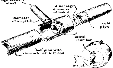
The vortex tube was invented accidently in 1933 by George Ranque and later developed by Hilsch (1947). It is also known as Ranque-Hilsch vortex tube (RHVT). The vortex tube is a device which separates a high pressure flow entering tangentially into two low pressure flows, there by producing a temperature change. The vortex tube has no moving parts and generally consists of a circular tube (main body), inlet nozzle, nozzle chamber, cold end tube, hot end control valve and hot tube. High pressure gas enters the vortex tube tangentially through the nozzles which increases the angular velocity and thus produces a swirl effect. There are two exits in the vortex tube. The hot exit is located in the outer radius near the far end of the nozzle and the cold exit is in the centre of the tube near the nozzle The difference in the temperature produced due to the swirl flow was first observed by Ranque during the study of dust separation cyclone and he referred it as “temperature separation”.
1.1 History
The vortex tube was invented in 1933 by French physicist Georges J. Ranque. German physicist Rudolf Hilsch improved the design and published a widely read paper in 1947 on the device, which he called a Wirbelrohr (literally, whirl pipe).The vortex tube was used to separate gas mixtures, oxygen and nitrogen, carbon
dioxide and helium, carbon dioxide and air in 1967 by Linderstrom-Lang.Vortex tubes also seem to work with liquids to some extent, as demonstrated by Hsueh and Swenson in a laboratory experiment where free body rotation occurs from the core and a thick boundary layer at the wall.
[image:1.595.347.534.392.504.2]The current: At the present time, tubes with the vortex were finally considered as a far more reliable device having its many uses. Users found that vortex tube is not just efficient but is cheaper when compared with other devices. Compressed air is well separated into cold and warm streams with this mechanical gadget. Without any movable parts, it hardly needs any maintenance.
Fig -1: Ranque-Hilsch vortex tube
1.2 Temperature separation effect
© 2017, IRJET | Impact Factor value: 5.181 | ISO 9001:2008 Certified Journal | Page 792 While there may and indeed are many different theories
[image:2.595.51.272.175.257.2]as to how the temperature separation in the RHVT takes place, only the following three will be considered: i) the viscous-shear theory, ii) the secondary flow theory and iii) the refrigeration cycle theory.
Fig 2: Temperature separation effect
2 Applications
o Cooling electronic controls.
o Cooling soldered parts.
o Cooling gas samples.
o Electronic component cooling.
o Cooling heat seals.
o Spot cooling of camera lens.
o Cutting of gas turbine rotor blades.
o Cooling machining operations.
o Setting hot melts.
o Cooling environmental chambers.
2.1 Advantages
o Maintenance free (No moving parts).
o Cools without costly electricity or refrigerants.
o Reliable, compact and lightweight.
o Low cost application.
o Durable - Stainless Steel.
o Adjustable temperature.
o Instant cold air.
3 PRESENT WORK
3.1 Objectives
To study The effect of materials on the performance of vortex tube.
The effect of pressure variation on the performance of stainless steel and mild steel vortex tube.
The effect of length variation on the performance of stainless steel and mild steel vortex tube.
The effect of inner diameter variation on the performance of stainless steel and mild steel vortex tube.
The effect of L/d ratio on the performance of stainless steel and mild steel vortex tube.
The effect of dc/d ratio on the performance of
stainless steel and mild steel vortex tube.
3.2 Methodology
The experiment is conducted on fabricated stainless steel and mild steel vortex tube. Main body of size (i.e length 250mm and outer diameter 20mm), with different inner diameter (i.e 4mm, 6mm and 8mm). Both main body individually connected to nozzle chamber at one end and nozzle is placed tangentially to the inlet. The cold end is thus connected to the nozzle chamber. Whereas another end is connected to hot end.
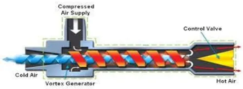
The vortex tube is a device which separates a high pressure flow entering tangentially into two low pressure flows, there by producing a temperature change. Swirl Effect is obtained by High pressure gas enters the vortex tube tangentially through the nozzles which increases the angular velocity. The outer air is under high pressure than the inner air because of centrifugal force. Therefore the temperature of outer air is more than that of the inner air. At the end of the tube a small portion of this air exits through a needle valve as a hot air exhaust. The remaining air is forced back through the centre of inlet air stream and exits through a cold outlet as cold air exhaust.
Experiments for different pressures (i.e 5bar, 6bar and 7bar) and different lengths (i.e 250mm, 270mm and 290mm) are conducted for three different inlet diameters. Measurements like temperature of inlet air, temperature of hot outlet air and temperature of cold outlet air are recorded using thermocouple with digital indicator.
Fig -4: Method of operation
4 EXPERIMENTAL SETUP
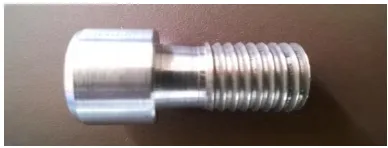
4.1 Main body:
This is done on 25mm diameter and 280mm length ingot of mild steel and stainless steel material separately. Then turned to a diameter of 20mm and length 250mm. External threads of 14 TPI is machined to a length of 50mm on either side of vortex chamber. To provide vortex action a hole of 4mm, 6mm, 8mm are drilled throughout the length on three different tubes. The holes are drilled using wire cutting method.
[image:2.595.309.555.447.537.2]© 2017, IRJET | Impact Factor value: 5.181 | ISO 9001:2008 Certified Journal | Page 793
[image:3.595.308.514.162.236.2]Fig -5 : Main body
4.2 Cold tube
This is done on 50mm length and 30mm diameter ingots of mild steel and stainless steel material separately. Then it is turned to a length of 45mm and 28mm diameter, and step turned from one side of the tube to a length of 25mm and 20mm diameter and 14 TPI threads are machined on the outer periphery to a length of 25mm.
[image:3.595.34.228.306.380.2]Material: Stainless steel
Fig -6: Cold tube
4.3 Hot tube
This is done on 30mm diameter and 95mm length ingots of mild steel and stainless steel separately. Then the material is turned to a diameter of 28mm and 90mm length. A hole of 16mm is drilled throughout the length. A part fixed to main body is then bored to a diameter of 20mm upto a length of 70mm and internal threads of 14 TPI are machined. Whereas, internal threads of 11 TPI are machined to a length of 20mm towards control valve end. A hole of 3mm dia is drilled to a depth of 6mm at a distance of 10mm from valve end.
Material: Stainless steel
Fig -7: Hot tube
4.4 Nozzle chamber:
This is done on 40mm diameter and 110 mm length ingots of mild steel and stainless steel separately. It is then step turned to a diameter of 28mm upto a length of 50mm on vortex chamber side and 20mm on cold tube side respectively. Then the remaining 20mm part is eccentrically turned with eccentric distance of 5mm. A hole of 20mm is drilled throughout the length and internal threads of 14 TPI
are machined throughout a length. Then a hole of 8mm is drilled on the eccentric part to a depth of 9mm which act as a inlet.
Material: Stainless steel
Fig -8: Nozzle chamber
4.5 Orifice
This is done on 20mm diameter ingots of mild steel and stainless steel separately. It is then turned to diameter of 19mm and thickness of 7mm. To provide swirling action a hole of 4mm, 6mm, 8mm are drilled on three different orifices.
Material: Stainless steel
Diameter: 4mm Diameter: 6mm Diameter: 8mm
Fig -9: Orifice
4.6 Specifications
[image:3.595.308.539.365.460.2]The dimensions and materials used for the different components of experimental setup are listed below.
[image:3.595.308.571.545.781.2]© 2017, IRJET | Impact Factor value: 5.181 | ISO 9001:2008 Certified Journal | Page 794
4.7 Nozzle
This is done on 20mm diameter ingots of mild steel and stainless steel separately. It is then turned to diameter of 19mm and thickness of 7mm. To provide swirling action a hole of 4mm, 6mm, 8mm are drilled on three different orifices and a profile has been cut at 450.
Material: Stainless steel
[image:4.595.319.527.93.424.2]
Diameter: 4mm Diameter: 6mm Diameter: 8mm
Fig -10: Nozzle
5 RESULTS AND DISCUSSIONS
Experiments were carried out on test rig for stainless steel and mild steel vortex tube for various parameters like tube length of 250mm, 270mm and 290mm, inner diameter of 4mm, 6mm and 8mm and at a pressure of 5 bar, 6 bar and 7 bar respectively.
According to the variations in tube length, inner diameter and pressure for different tubes the results have been illustrated. The variation of the pressure for different tubes the maximum temperature drop is observed at 6 bar. The variation in tube length and inner diameter also effects the temperature difference and it is noticed that peak temperature drop is observed at a length of 250mm and inner diameter of 4mm. It is also observed that the better results were observed for stainless steel tubes.
Table 2: Various parameters for stainless steel vortex tube at pressure 6 bar
For inner diameter 4mm and pressure 6 bar ti – 36 oc
th – 37 oc
tc – 25 oc
i) Cold temperature drop Δtc = ti - tc
= 36 – 25
Δtc = 11 oc
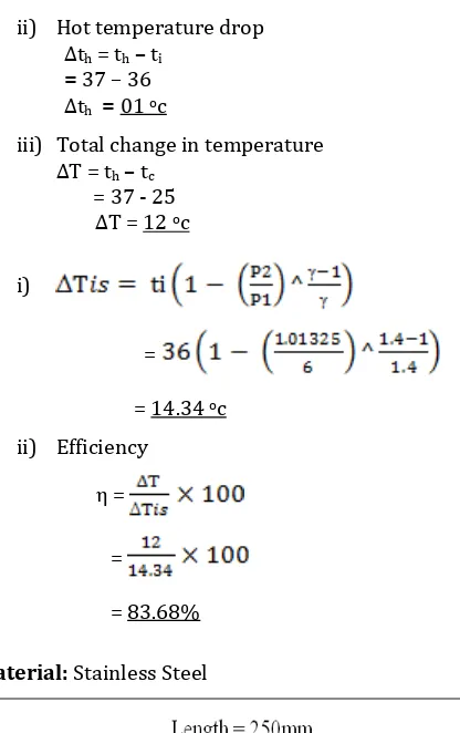
ii) Hot temperature drop Δth = th – ti
= 37 – 36
Δth = 01 oc
iii) Total change in temperature ΔT = th – tc
= 37 - 25
ΔT = 12 oc
i)
=
= 14.34 oc
ii) Efficiency
η =
=
= 83.68%
Material: Stainless Steel
Fig -11: Pressure vs Δtc for length 250mm
[image:4.595.37.274.200.299.2]© 2017, IRJET | Impact Factor value: 5.181 | ISO 9001:2008 Certified Journal | Page 795
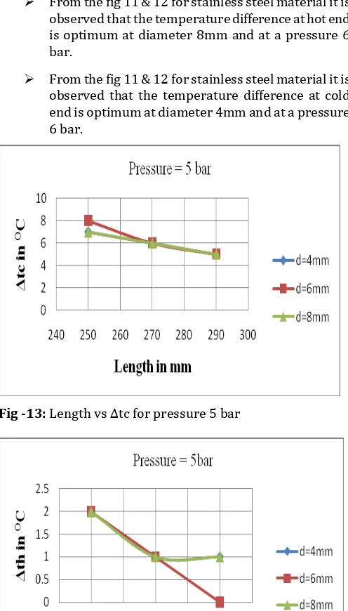
From the fig 11 & 12 for stainless steel material it is observed that the temperature difference at hot end is optimum at diameter 8mm and at a pressure 6 bar.
[image:5.595.306.564.87.261.2] From the fig 11 & 12 for stainless steel material it is observed that the temperature difference at cold end is optimum at diameter 4mm and at a pressure 6 bar.
Fig -13: Length vs Δtc for pressure 5 bar
Fig -14: Length vs Δth for pressure 5 bar.
From the fig 13 & 14 for stainless steel material it is observed that the temperature difference at hot end is optimum for tube length of 250mm.
[image:5.595.37.285.104.539.2] From the fig 13 & 14 for stainless steel material it is observed that the temperature difference at cold end is optimum for tube length of 250mm.
[image:5.595.309.561.295.472.2]Fig -15: L/d vs Δtc for inner diameter 4mm
Fig -16: L/d vs Δth for inner diameter 4mm
From the fig 15 to 16 for stainless steel material it is observed that the temperature difference at cold end is optimum for an L/d ratio of 62.5.
From the fig 15 to 16 for stainless steel material it is observed that the temperature difference at hot end is optimum for an L/d ratio of 62.5.
6 CONCLUSION
From the results and discussions the following conclusion were made:
The temperature difference at cold and hot end is optimum for stainless steel vortex tube .
The maximum temperature drop at cold and hot end for stainless steel material is observed at tube length of 250mm.
[image:5.595.35.283.410.592.2]© 2017, IRJET | Impact Factor value: 5.181 | ISO 9001:2008 Certified Journal | Page 796 stainless steel material is observed at pressure of 6
bar.
The maximum temperature drop at hot end for stainless steel material is observed at inner diameter of 8mm.
The maximum temperature drop at cold and hot end stainless steel material is observed at an L/d ratio of 62.5.
7 REFERENCES
[1] Shreetam Dash “Numerical analysis in Ranque-Hilsch vortex tube”, National Institute of Technology, Rourkela, 2010.
[2] A.M.Dalavi “Modeling, optimization and Manufacturing of vortex tube and application”, IOSR Journal of Mechanical and Civil Engineering, M.E.Society’s college of engineering, pune, India.2012, PP:45-49.
[3] Upendra behera “CFD analysis and experimental investigations towords optimizing the parameters of Ranque-Hilsch vortex tube”, Department of Aerospace engineering, Indian institute of science, Bangalore, India, 2000.
[4] Maziar Arjomandi “Influence of the vortex angle on the efficiency of the Ranque-Hilsch vortex” , lecturer, school of mechanical engineering, The University of Adeliade, Adeliade, Australia, 2008. [5] Ratnesh Sahu “Performance Analysis of a vortex
tube by using compressed air” ,International journal of scientific and engineering research volume 3, Issue 9, September 2012.
[6] Mahyar kargaran “The second law of analysis of natural gas behavior within a vortex tube” , The faculty of mechanical engineering Shahrood university of technology, Sharood Iran, 2013, volume 17, No.4, pp.1079- 1092.
[7] Mahyar kargarn “Experimental investigation the effects of orifice diameter in tube length vortex tube performance”, International Journal of recent advances in Mechanical engineering volume.2 No3, Department of mechanical engineering university of technology , Sydney Australia, August 2013.
BIOGRAPHIES
Serving as Asst. Prof, Department of Mechanical Engineering K. L. E. Institute of Technology, Hubballi-30. Completed M.Tech in (Thermal Engineering). Have an academic experience of about 6 years.
"Student", Mechanical Engineering, K.L.E.I.T., Hubballi.