© 2017, IRJET | Impact Factor value: 5.181 | ISO 9001:2008 Certified Journal | Page 2673
A Comparative Analysis of Structure of Machine Tool Component Using
Fuzzy Logic
Lomit Kumar Sao
1, Dr. Harsh Pandey
21
M-Tech Scholar, Dept. of Production Engg., Dr. C. V. Raman University, Kota- Bilaspur(C.G.), India.
2HOD, Dept. of Mechanical Engg., Dr. C. V. Raman University, Kota- Bilaspur(C.G.), India.
---***---Abstract –
Design of structures for various machine tools is very complex and conventional methods suggested by authors of text books present different methodologies. Trial and error is adopted to arrive at optimum values. Utilization of FEM, Multi value optimization and tools like ANSYS is reported in literature. In this work a fuzzy based approach is suggested for selection of optimum structure for bed. A comparison of I-section and box I-section is presented. Result clearly shows that I-section gives lower stress values compared to box section. Advantages of fuzzy approach are presented.Key Words: Fuzzy Logic, Machine Tool Design and Lathe Bed.
1. INTRODUCTION
Machine tool industry of the world produces a large number of machine tools differing in purpose, processing capabilities and size. Every machine tool produced contains a supporting frame, bed or column or knee. In machine tools this structures account for 70-90% of the total weight of the machine. Hence design and development of beds is one of the important part of the production engineering management. Structures are designed for strength and rigidity. Different materials are used for design of beds. Gray cast iron and carbon steel are among the widely used material.
Design of bed structures by authors of text books on machine tools like Mehta [1], Acherkan [2], Sen and Bhattacharya [3] present trial and error based methodologies to arrive at optimum values. A great deal about general engineering design is presented in Dieter [4]. Klir and Yuan [5] presented an application of fuzzy set theory, fuzzy logic and fuzzy measure theory in the field of engineering. Antonsson and Otto [6] presented a method on turning parameters in engineering design. Otto et al. [7] presented method of imprecision, a formal method, based on mathematics of fuzzy sets, for representing and manipulating imprecision in engineering design. Antonsson et al. [8; 9; 10] suggested a technique to perform design calculations on imprecise representations of parameters. The level of imprecision in the description of design elements is typically high in the preliminary phase of engineering design. This imprecision is represented using the fuzzy calculus. Zadeh [11] explained about fuzzy sets that a fuzzy set is a class of objects with a continuum of grades of membership. Such a set is characterized by a membership function which assigns to
each object a grade of membership ranging between zero and one. The technology of fuzzy set theory and its application to systems was presented by Ross [12].
2. COMPARATIVE DESIGN OF BED
Design of bed using a conventional method [1] is presented with the help of an example.
2.1
Design by Conventional Method
A part of diameter 200 mm and length 1500 mm is supported between centres with a tightening load of 5000 N and machined on a lathe. The cutting force components were recorded with a dynamometer as Px = 2500 N, Py = 5000 N
[image:1.595.325.540.408.613.2]and Pz = 10000 N.
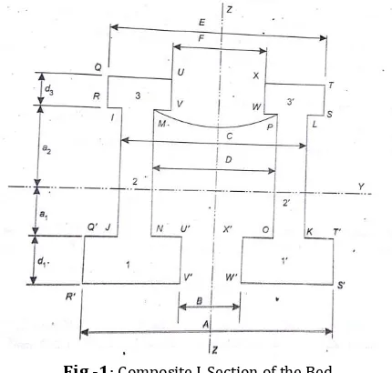
Fig -1: Composite I-Section of the Bed
Design for I-Section:
Considering an I-section as shown in Fig. 1 as given below with assumed dimensions. The dimensions of the bed sections are as follows b1 = 110 mm, b2 = 20 mm, b3 = 115
mm, d1 = 30 mm, d2 = 315 mm, d3 = 25 mm, A = 365 mm, B =
145mm, C = 275 mm, D = 235 mm, E = 370 mm, F = 140 mm. The data related to the machine tool is as follows: Height of centres h = 300 mm, distance of the feed pinion from the bed surface hfp = 50 mm. Ignoring the weight of the work-piece.
© 2017, IRJET | Impact Factor value: 5.181 | ISO 9001:2008 Certified Journal | Page 2674 The first step is to determine the position of the neutral axis
of the bed section. Taking the moment of the section about the lower most edge, we find
Hence, ẑ= z1 = 181.05 mm and z2= d1+d2+d3- z1 = 188.95 mm
a1 = z1 - d1 = 151.05 mm and a2 = z2 - d3 = 163.95 mm
As the two I-sections are symmetrical about the Z-axis
ẏ = 0
Now, the moment of inertia about Y-Y and Z-Z-axis are Iyy = 466508061.3 mm4,
Izz = 419005416.7 mm4 and
It = 885513478 mm4
We now determine the maximum normal and shear stresses in the bed section
For the composite bed section, zmax = max [z1, z2] = max
[181.05, 188.95] Hence, zmax = 188.95 mm. Ignoring the
weight of the work-piece, we find σzmax = 2.58 N/mm2
For the composite bed section, ymax = max [A/2,E/2] = max
[365/2, 370/2] Hence, ymax = 185.00 mm. Substituting the
values of the various parameters, we find σymax= 0.83 N/mm2
For the given composite bed section, max[ymax, zmax] = max
[185.00, 188.95] Hence, max[ymax, zmax] = 188.95 mm.
Substituting the values of the various parameters, we find
τmax = 0.53 N/mm2
Knowing σymax; σzmax and τmax we determine the principal
stress from the expression,
On substituting the values, we find σpmax = 2.73 N/mm2
As σpmax is less than the allowable stress it may be concluded
that the bed design is safe in terms of strength.
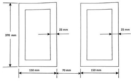
Design for Box Section:
Using similar dimensions for box section as shown in Fig. 2. The first step is to determine the position of the neutral axis of the box section. Taking the moment of the section about the lower most edge, we find
ẑ = 185 mm
Hence, ẑ= z1 = 185 mm and z2 = 185 mm
a1 = z1 - d1 = 155 mm and a2 = z2 - d3 = 160 mm
As the box sections are symmetrical about the Z-axis
ẏ = 0
Now, the moment of inertia about Y-Y and Z-Z-axis are Iyy = 372696875 mm4,
Izz = 79062500 mm4 and
It = 451759375 mm4
We now determine the maximum normal and shear stresses in the bed section
For the composite bed section, zmax = max [z1, z2] = max
[185, 185] Hence, zmax = 185 mm. Ignoring the weight of the
work-piece, we find σzmax = 3.1644349 N/mm2
For the composite bed section, ymax = max [A/2,E/2] = max
[365/2, 370/2] Hence, ymax = 185.00 mm. Substituting the
values of the various parameters, we find σymax= 4.3873518
N/mm2
For the given composite bed section, max[ymax, zmax] = max
[185.00, 188.95] Hence, max[ymax, zmax] = 185 mm.
Substituting the values of the various parameters, we find
τmax = 1.0237751 N/mm2
Knowing σymax; σzmax and τmax we determine the principal
stress from the expression,
On substituting the values, we find σpmax = 4.9683684 N/mm2
As σpmax is less than the allowable stress it may be concluded
[image:2.595.322.535.488.620.2]that the bed design is safe in terms of strength.
Fig -2: Composite Box Section of the Bed
2.2 Design by Fuzzy Logic Method
The most important parameter in the design of bed is the cross section geometry and corresponding section modulus. Since the geometry of I-section and box section are simple, it is generally considered as first choice for analysis. The parameters which govern the overall stress calculations are the section modulus Iyy, Izz and It. The preference regarding
© 2017, IRJET | Impact Factor value: 5.181 | ISO 9001:2008 Certified Journal | Page 2675 The section modulus for I-section and box section about
Y- and Z-axis are represented by the following fuzzy sets which are triangular fuzzy numbers shown in Table 1 below;
Table - 1: Fuzzy Set for I-section and Box section
I-Section Iyy = {186603225, 466508061, 793063704}
Izz = {167602167, 419005417, 712309208} It = {354205391, 885513478, 1505372913}
Box Section Iyy = {149078750, 372696875, 633584688}
Izz = {31625000, 79062500, 134406250} It = {180703750, 451759375, 767990938}
where the middle value represent the term with highest preference and the two extremes are lower and upper limits respectively.
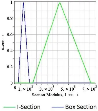
[image:3.595.350.519.333.524.2]The discrete α-cuts of the three variables from the Chart 1, 2 and 3 are shown in Table 2 and 3.
Table -2: Section Modulus of I-Section for Various Values of α-cuts
α-Cuts Iyy (108) mm4 Izz (108) mm4 It (108) mm4
0.2 {2.38, 7.23} {2.11, 6.51} {4.15, 13.8}
0.4 {2.95, 6.57} {2.65, 5.90} {5.61, 12.3}
0.6 {3.55, 5.91} {3.15, 5.33} {6.72, 11.2}
0.8 {4.08, 5.23} {3.65, 4.69} {7.74, 10.0}
[image:3.595.351.515.561.748.2]1.0 {4.69} {4.12} {8.85}
Table -3: Section Modulus of Box Section for Various Values of α-cuts
α-Cuts Iyy (108) mm4 Izz (107) mm4 It (108) mm4
0.2 {1.91, 5.80} {4.08, 12.2} {2.30, 6.94}
0.4 {2.35, 5.26} {5.05, 11.1} {2.81, 6.38}
0.6 {2.85, 4.76} {5.97, 10.0} {3.42, 5.77}
0.8 {3.28, 4.26} {6.94, 8.93} {3.98, 5.15}
1.0 {3.72} {7.86} {4.54}
Based on these discrete α-cuts of the input parameters, applying the functional relationship valid for the problem, we get the following discrete α-cuts of the performance parameter, σ, as from the Chart 4.
0.2σ = {9.09, 18.73} 0.4σ = {10.42, 17.48} 0.6σ = {11.52, 16.30} 0.8σ = {12.77, 15.20}
1.0σ = {13.95}
Chart -1: Fuzzy Set for Section Modulus Iyy
Chart -2: Fuzzy Set for Section Modulus Izz
© 2017, IRJET | Impact Factor value: 5.181 | ISO 9001:2008 Certified Journal | Page 2676 From the values of discrete α-cuts of the induced set G on the
performance parameter, σ, the membership function of the set G is drawn on Chart 4.
Chart -4: Fuzzy Set for Superposition of σ, G and NEp
Now, the performance parameter, σ i.e. the allowable stress should not be excessive. For a given material, let the range of values be 12 to 20 N/mm2. The fuzzy set NE defined as
Comparing the value of σ for which the membership function has its maximum with NE as shown in Chart 4, we find that this value is 18.73, hence it does satisfy the requirement that the allowable stress should not be excessive. Consequently the values of the input parameters with the highest preference could not be used. To obtained the optimal value,
σ* of the performance parameter, we find a value of σ that lies on the intersection of the sets G and NE with the highest membership grade. That is, σ* is the value of σ for which
is obtained. This results in σ* = 13.11 N/mm2 Corresponding
to this value of σ*, we have the membership grade as α =
G(σ*) = 0.86.
[image:4.595.89.235.145.303.2]Corresponding to this value of α, the α-cuts of the input parameters are
Table - 4: α-Cuts of the Input Parameters
I-Section 0.86Iyy = {4.29×10⁸, 5.03×10⁸}
0.86Izz = {3.85×108,4.57×108} 0.86It = {8.06×108,9.49×108}
Box Section 0.86Iyy = {3.48×108,4.12×108}
0.86Izz = {7.27×107,8.91×107} 0.86It = {4.24×108,4.85×108}
Then, the corresponding optimum values of the input parameters Iyy*, Izz*, and It* for the I-section and box section
are
Table - 5: Optimum Parameters
I-Section Iyy* = 5.03×10
8mm4 Izz* = 4.57×108mm4 It* = 9.49×108mm4
Volume = 18712500 mm3
Box Section Iyy* = 4.12×10
8mm4 Izz* = 8.91×107mm4 It* = 4.85×108mm4
Volume = 36000000 mm3
3. RESULT
Considering the volume of the sections it is found that the I-section is having lower values compared to the box I-section and corresponding stress is lesser as well hence recommended for design of bed.
4. CONCLUSIONS
Conventional methodology requires trial and error in order to reach conclusion and depends on designer’s intuition and knowledge. Fuzzy approach uses range of values to arrive at optimum values. Initial guess is required and the imprecision in initial phase is taken care of by the method. Further work is being done to incorporate many other structural characteristic as well.
REFERENCES
[1] Mehta, N. K. (2012), Machine Tool Design and Numerical Control. Tata McGraw Hill Education Private Limited, New Delhi.
[2] Acherkan, N.;Push, V.;Ignatyev, N. and Kudinov, V. (1969), Machine Tool Design Vol. 3. Mir Publication, Moscow. [2] Antonsson, E. K., and Wood, K. L. (1990), Modeling Imprecision and Uncertainty in Preliminary Engineering Design. Mechanism and Machine Theory, 25(3):305-324. [3] Sen, G. C. and Bhattacharya, A. (2009), Principals of Machine Tools. New Central Book Agency (P) Ltd, Kolkata. [4] Dieter, G. E. (2000), Engineering Design (Third Ed.). Singapore: Mcgraw Hill.
[5] Klir, G. J., and Yuan, B. (2000), Fuzzy Sets and Fuzzy Logic: Theory and Applications. Prentice-Hall of India Private Limited, New Delhi.
[6] Otto, K. N., and Antonsson, E. K. (1991), Research of Imprecision Methods for Quality Engineering Design at Caltech. California Institute of Technology, Mechanical Engineering, California.
[7] Wood, K. L., Otto, K. N., and Antonsson, E. K. (1992), Engineering Design Calculations with Fuzzy Parameters. Fuzzy Sets and Systems, 52(1):1-20.
[8] Wood, K. L., and Antonsson, E. K.(1989) , Computations
[image:4.595.315.550.161.243.2]© 2017, IRJET | Impact Factor value: 5.181 | ISO 9001:2008 Certified Journal | Page 2677 Design:Background and Theory. ASME Journal of
Mechanisms, Transmissions and Automation in Design, 111(4):616-625.
[9] Wood, K. L., Antonsson, E. K., and Beck, J. L. (1990), Representing Imprecision in Engineering Design: Comparing Fuzzy and Probability Calculus. Research in Engineering Design, 1(3-4):187-203.
[10] Wood, K. L., Otto, K. N., and Antonsson, E. K. (1990), A Formal Method for Representing Uncertainties in Engineering design. Workshop on Formal Methods in Engineering Design Fort Collins, Colorado, 202-246. [11] Zadeh, L. A. (1965), Fuzzy sets. In Information and Control, pp.338-353.