© 2018, IRJET | Impact Factor value: 6.171 | ISO 9001:2008 Certified Journal | Page 1328
SMART SHOCK ABSORBER
Sayed Shabaz
1, Sayyed Azharuddin
2, Shinde Nitin
3, Shinde Vishwas
4, Deshmukh Mahesh
51,2,3,4 BE Student, Mechanical, SND COE & RC, Yeola Maharastra, India 5Asst. Prof. Mechanial, SND COE & RC, Yeola, Maharastra, India
---***---Abstract - Automobiles and trucks have shock absorbers
to damp out the vibration experienced due to roughness of the roads. However, energy in conventional shock absorber gets dissipated as heat and it is not use in anyway. We know that in conventional vehicle suspension dissipates the mechanical vibration energy in the form of heat which considerable waste energy. If the vibration energy can be recovered and converted to other form of energy so as to supply for other devices then the aim of eco-friendly energy saving is reach. And this energy is used to charge the battery and this stored energy is used for different vehicle accessories.
Key words: D.C. Generator, Energy generation, Rack & pinion, Vehicle Suspension
1. INRODUCTION
Energy means, capacity to do work. This is the most important requirement for mankind. In our daily life, we can see various forms of energy storing and as well as energy dissipation. In most cases the energy is wasted. So there is a very specific & precise scope for increasing the average. But there is wide scope for regeneration of energy like regeneration of braking system etc. we have decided to work on utilization of suspending mass of a vehicle through regeneration system with help of a shock absorber. Shock absorber are having reciprocating motion in it. Although the reciprocating distance is very low the suspending mass is very high i.e the mass of total vehicle. When vehicle is on normal roads, even then shock absorbers are working due to uneven roads, sudden breaking or sudden acceleration. So this reciprocating motion of shock absorber can be converted into rotary motion. If a small gear box is attached to alternator of automobile such that electricity will be generated when shock absorbers will be reciprocating. When vehicle will pass through a dump or pit, that time high energy will be generated through alternator. Battery is connected to the alternator, such that battery will be charged due suspension system. Currently the batteries of automobiles are charged by specific alternator which is attached to IC engine shaft. So that the fuel used in automobiles is also consumed for rotating the alternator to charge the battery. This consumption is found to be 4% of the total consumption. By newly designed suspension regeneration system presently using alternator is detached from the engine and attached to the suspension system. If we install this regeneration system for all 4 wheels then we can generate high amount of electric power. This high amount
of electric power can be used for the working of car air conditioner or refrigeration system of vehicles. This suspension system will be mostly useful for heavy compressed vehicles, milk trucks, fire brigade trucks and also those having high requirement of electricity inside it.
2. PROBLEM DEFINITION
The internal combustion engine used in current automobiles has efficiency of around 30% to 40%. From this small efficiency, apart from generating tractive effort for vehicle movement the engine has to run various systems such as lighting system, air conditioning system, ECU of vehicle, etc. The alternator used to charge battery is directly coupled to engine shaft. As a result of it, the alternators directly or indirectly consume brake power obtained at engine shaft with very low efficiency. The amount of energy consumed by the alternator is approximately 4% of total energy generated. So this creates a situation for us where need to replace the alternator to some system which will not add up to the engine load and also recover the waste energy which is dissipated to the surrounding. As per research, we could find two such systems which have high energy potential and is not being utilised i.e. brake power and suspension power. Suspension system seem to be more promising so we decided to develop a system which regenerates the energy obtained from the continuous displacement of suspension system. If we couple this system to all four wheels of vehicle, it can fulfil the demand of charging battery. This electricity can later be supplied to other systems.
[image:1.595.344.506.604.732.2]
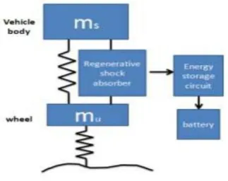
3. REGENERATIVE SUSPENSION SYSTEM
© 2018, IRJET | Impact Factor value: 6.171 | ISO 9001:2008 Certified Journal | Page 1329 3.1 ENERGY DISSIPATION FROM VEHICLE
SUSPENSION
In the past, we have little attention towards energy loss of vehicle suspension. However, how much energy is dissipated by the shock absorbers of vehicle suspension? According to reference, only 10-20% the fuel energy is used for vehicle mobility. One of the important losses is the energy dissipation in suspension vibration. Velinsky et al. [1]
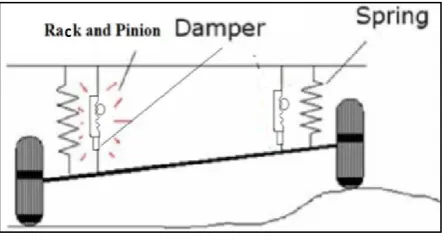
4. CONCEPT OF PROJECT
In this project we have to develop a suspension energy generation unit by using rack and pinion method. It is less costly than the hydraulic unit.
Part of the system:
Standard Parts:
1) Wheel assembly. 2) Suspension unit. 3) Rack and pinion. 4) Generator.
Manufacturing Parts:
1) Chassis
2) Wheel mounting 3) Gear Box
Because of reciprocating motion the pinion is rotating and suspension do work. This rotation of pinion we have converted in to high RPM by using gear box. At the of gear box we have attached a generator to generate electricity.
Fig.2: Concept of Project
4.1 RACK AND PINION ASSEMBLY
[image:2.595.312.557.302.447.2]Rack and pinion gears are used to convert rotation into linear motion. The flat, toothed part is the rack and the gear is the pinion. A rack and pinion gears system is composed of two gears. The normal round gear is the pinion gear and the straight or flat gear is the rack.
Fig.3: rack and pinion assembly
4.2 D.C. GENERATOR
A generator is a device that converts motive power (mechanical energy) into electrical power for use in an external circuit. Sources of mechanical energy include steam turbines gas turbines water turbines, and internal combustion engine.
Fig.4: DC Generator
4.3 ALTERNATOR
[image:2.595.54.276.531.656.2]© 2018, IRJET | Impact Factor value: 6.171 | ISO 9001:2008 Certified Journal | Page 1330 Fig.5: Alternator
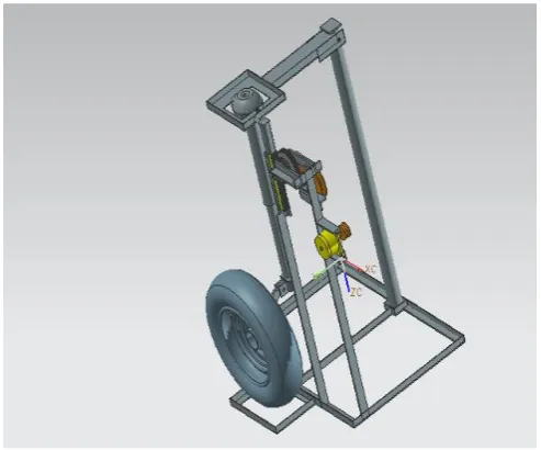
[image:3.595.39.284.89.490.2]5.CAD MODEL
Fig.6: CAD layout of the project
Fig.7: CAD layout of the project
6. DESIGN PARAMETERS
Table 1: Parts Specification
Parts Specificaton (in mm)
Rack 175(length)
Pipe 1 100(length)
Pipe 2 1000(length)
Gear 1 Φ 8.5
Gear 2 Φ32.5
Gear 3 Φ47.5
Shaft 1 Φ16
Shaft 2 Φ25
Pulley 1 Φ103
Pulley 2 Φ40
Bearing Φ28
7. DESIGN
Calculation example:
Vertical lift of body e.g. 5mm per meter travelled. Energy calculation according to the known energy formula is force times distance. The vertical lift is 500 meters for every 100km traveled. Vehicle weight 2000kg. vertical lift of body e.g. 5mm per meter travelled
Energy=force*displacement
Total energy of the vertical body=2.8kWh
8. SUMMARY
As can be seen in the computer evaluation below:
[image:3.595.38.285.523.728.2]Gross vehicle weight 1600kg (Passenger Car- 2 axles/ 4 wheels). Wheel load 400kg per wheel – unsprang weight(wheel unit): 40kg
Table 2: Energy yield
Excitation Wheel mm /
meter travelled Total Yield
±5mm 0.9kWh
±10mm 2.4kWh
±25mm 7.5kWh
±50mm 16.8kWh
9. COMMENTS
[image:3.595.336.527.588.676.2]© 2018, IRJET | Impact Factor value: 6.171 | ISO 9001:2008 Certified Journal | Page 1331
resulting excited state (wheel suspension length and frequency). We have not allowed for various energy losses on voltage conversion and in battery storage or hydraulic energy losses through flow loss in electrically regulated cylinders here. These losses and variable parameters will be shortly reviewed in detail by a German university institute and subsequently included in the maximum current yield calculation. This means we will be able to make a substantiated statement about the actual amount of energy available and thereby define the achievable range extension.
10. RESULT
With a higher total weight, the energy yield is likewise much higher. The body weight thus has a direct effect on the amount of electricity produced by the "electricity-generating suspension system"
11. SPECIAL FEATURES OF PROJECT
Now deals suspension energy available in electric car. In this project we are reply hydraulic system to electric generation with a mechanical system. In over project we are used rack and pinion adjustment for a electricity generation this system is low cost as compare to hydraulic system. Also low maintenance as compare to hydraulic system. We have to achieve this project electricity generation with the car.
12. CONCLUSION
Energy is an indirectly observed quantity, which cannot be created or destroyed, but any form of energy can transform in to another form. The vibration energy of vehicle is dissipated as heat by shock absorber, which wastes a considerable number. With help of smart shock absorber we can recycle this waste energy. If we installed this system for all wheel then we can generate high amount of electricity.
ACKNOWLEDGEMENT
While presenting this project, we are glad to convey our thanks to the people who guided us and help us at every stage of our project. We deeply acknowledge the support of our Head of Department Prof. Bhamre V.G. for his valuable input and constant guidance in successful completion of our project. We also thank our project guide Prof. Desmukh M.S and giving their valueable time and guiding us throughout in the development of our project.
We express our sincere gratitude to the librarian who has provided her co-operation towards the completion of reference work. Most importantly we would like to express our sincere gratitude towards our Friends & Family for always being there when we needed them most.
REFERENCES
[1] Zhongjie Li, Lei Zuo*, JianKuang, and George Luhrs ,Department of Mechanical Engineering, State University of New York at Stony Brook, Stony Brook, NY, 11794
[2] Pei S.Z., “Design of Electromagnetic Shock Absorbers for Energy Harvesting from Vehicle Suspensions”, Master Degree Thesis, Stony Brook University, 2010.
[3] Y. Zhang, F. Yu, and K. Huang, “A state of the art review on regenerative vehicle active suspension,” in Proc. 3rd ICMEM, Beijing, China, Oct. 21–23, 2009, pp.1689–1695.
[4] Pedro Portela, JaaoSepulveda, Joao Sena Esteves, “Alternating current and direct current Generator”, Sep 3, 2008.
[5] Rahul Uttamrao Patil, Dr. S. S. Gawade, “Design and static magnetic analysis of electromagnetic regenerative shock absorber”.
[6] 1. Quick, Darren. "Regenerative Shock Absorber to Bump up Car Energy Capture
[7] Capabilities." Gizmag | New and Emerging Technology News. 19 Mar. 2010. Web. 04 Dec.
[8] 2010. http://www.gizmag.com/regenerative-shock-absorber/14564/
[9] Andrea, Davide. "Li-Ion BMS - White Paper - Estimating the State Of Charge of Li-Ion
[10] Batteries."Li-Ion BMS - Lithium-Ion Battery Packs and Battery Management Systems
[11] Elithion, 1 Oct. 2009. Web. 14 Mar. 201
[12]www.howstuffworks.com.<http://auto.howstuffwork s.com/electric-car.htm>
[13] Electrical technology vol.2, B.L. Thareja, S. Chand publications.
[14] “Energy Recuperation in Automotive Active Suspension System with Linear Electric Motar”, By Antonin Stribrsky, Katerina Hyniova, jaroslav Honcu and Ales Kruczek
BIOGRAPHIES
Sayed Shabaz A. SND COE Yeola, Pune University, Department of Mechanical Engineering.
© 2018, IRJET | Impact Factor value: 6.171 | ISO 9001:2008 Certified Journal | Page 1332
Sayyed Azharruddin N. SND COE Yeola, Pune University, Department of Mechanical Engineering.
Shinde Nitin S. SND COE Yeola, Pune University, Department of Mechanical Engineering.
Shinde Vishwas B. SND COE Yeola, Pune University, Department of Mechanical Engineering.