2018 International Conference on Communication, Network and Artificial Intelligence (CNAI 2018) ISBN: 978-1-60595-065-5
Development and Experiment of an Automatic Measurement Device for
Water Coupling by Image Processing
Zheng LI, Da LU, Min-hong WAN, Xiao-yuan LIU and Hao-dong CHI
Shenyang Institute of Automation (SIA), Chinese Academy of Sciences (CAS), Shenyang, China
Keywords: Water coupling, Image processing, Automatic Measurement, Bubble trap, Indicator
verification.
Abstract. This paper describes an automatic measurement device for water coupling, which can
drive the water coupling doing automatic reciprocating motion and measuring the product indicator of air input by the result of image processing. The control software is developed by using STM32 processor, which deals with the reciprocating motion control and data acquisition. The correctness of working principle is verified through a series of experiments of automatic motion, and the product indicator is calculated based on image analysis theory. It can not only analyze and study the practical application for the products of water coupling, but also provide a new approach for automatic experiment and measurement in unmanned operation.
Introduction
There are a number of water circulation systems in the science cabinet, and the water circulation system can be connected and disconnected (on-off) quickly and conveniently by water coupling. High precision water coupling is the key part in the waterway, and if a large amount of air enters the interior of the circulation system in the process of on-off, it will cause a lot of bubbles accumulating in the waterway of science cabinet, which may affect the experimental results seriously. Therefore, the product indicator of air input is one of the most important technical indicators for the water coupling, and it is needed to be measured accurately. A large number of on-off operations should be carried out due to the significant value of the product indicator. An unmanned automatic measurement method is designed and the experimental device based on this principle has been developed. The purpose is to study the principle of air entering into the waterway during the on-off process when the water coupling works, and to provide an automatic measurement method and application for water coupling.
Water Coupling
The water coupling product is a valve designed and developed for using in waterway system, which is composed of a fixed end and a moving end, and the on-off of the waterway system can be controlled easily by rotating the moving side, thus the waterway system can be switched between on and off.
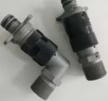
[image:1.612.267.345.645.718.2]With the rapid development of space technology in China, there are lots of requirements for water coupling products in waterway systems. Thus the research and analysis of the water coupling product by using this device is necessary. This will provide important technical support and practical experience for it used in the future. Figure 1 shows the standardized products of the water coupling.
The specifications of the water coupling are very strict, especially for application in space. If there is too much air entering the waterway system due to on-off, the water pipe will have a negative effect on the application systems. Due to a large number of on-off operations, the entered air is collected in a bubble trap in the waterway, and pictures are taken by two cameras when the valve works. The bubble outline can be calculated by image processing. So the technical indicators can be obtained. Table 1 shows the product indicators required of the water couplings.
Table 1. Technical indicators of the water coupling products. NO. indicators parameter
1 Air input (mL / time) 0.003
In order to validate the relevant indicators, it is necessary to carry out the measurement to obtain the actual measurement data. Therefore, the unmanned automatic experiment system is developed to complete the testing and verification for the specifications of the water coupling.
The Principle Design of the Testing Device for Water Coupling
Measuring Principle
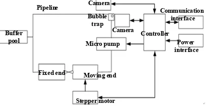
The mission of this device is to measure the product indicators of air input for the water coupling. It is necessary to design and develop an automatic measurement device instead of using manual operation to control the water coupling for reciprocating motion and to achieve measured data because of the large number times of on-off. Simultaneously, the device can also return the testing data back for analysis and processing. Therefore, the principle of measurement has been designed based on this conception, and the principle of which is shown in figure 2.
Moving end Fixed end
Buffer pool
Pipeline Camera
Camera
Micro pump
Controller
Communication interface
Power interface
Stepper motor Bubble
[image:2.612.209.413.386.492.2]trap
Figure 2. The measurement schematic of air input for water coupling.
The on-off switching operation of the water coupling is achieved by the linear motion whose moving end is driven by a Faulhaber DC motor that moves relative to the fixed end. The water is driven by a micro pump for circular movement in the pipeline when the water coupling is connected. If bubbles are contained in the water, they will gather into a big bubble when they pass through the bubble trap. Two cameras are placed respectively at two vertical directions of the bubble trap, and take pictures for the bubble whose geometric contour can calculate the volume of bubble through image processing technology. The control system will record the times of on-off switching operation during the reciprocating motion of the water coupling, and then calculate the product indicators of air input through the volume of the bubble divided by the number of times of reciprocating motion. Computational Method of Product Indicators
V3, n4, V4……are obtained, then the product indicators of air input Q (mL) will be calculated as follows:
Q=V/n (1) Where V ((Vi - Vj) (j>i)) is the increment between two images; n ((nj - ni) (j>i)) is the number of reciprocating movements between two images.
The product indicators of the water coupling can be calculated through this method of measurement. The more frequency of the movements, the more air it collects, and the more accurate the measurement result is.
System Design of the Testing Device
Mechanical Structure Design
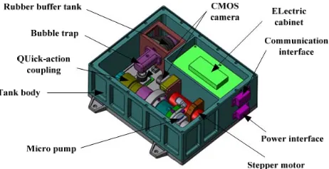
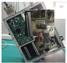
[image:3.612.191.422.306.425.2]The water in the device is an important risk source, which once leaked to the outside may have bad impact on the surrounding environment. According to the principle of safety and reliability, the internal structure of the device is divided into two cavities and arranged in a sealed rectangular box body. The structure of the device and the arrangement of each part in the case are shown in figure 3.
Figure 3. Structure of the testing device.
The two inner cavities of the device are respectively used for placing control system and waterway system. The control system and the waterway system are physically isolated to prevent water from leaking and causing short circuits and other hazards to the electronics system. The upper and the lower sides of the case are sealed by two sealing rings to prevent inner water from leaking to the outside of the case. The RS422 communication interface and the power supply interface are arranged on the side of the controller cavity in the body for the purpose of realizing power supply and communication with the outside.
Inside the case, the composition of the system components includes the water coupling, waterway circulation system, measurement system, motion system and the key mechanical parts such as buffer pool, micro pump, DC motor, guide rails and cameras, are fixed in the larger chamber. The control system is fixed inside the electric control box which is the smaller one, and is electrically connected with the DC motor, the micro pump, the LED lamps and the cameras through different cables, in addition, all the metal exposed areas and cable holes are dispensed with sealing and insulation. Motion Structure and Waterway System
Limit switches are installed on both sides of the linear guide rail, and the reciprocating motion is realized by the position detection. The cutaway view of the movement mechanism of the water coupling is shown in figure 4.
Figure 4. Waterway system and automatic reciprocating motion.
A closed waterway system is consisted of a water coupling, a micro pump, a buffer pool, a bubble trap and several transparent water pipes. The micro pump starts to work and drives water to circulate when the water coupling moves to the “on” position. The buffer pool is a retractable cabinet, which can buffer the internal volume change caused by the air input.
Control System
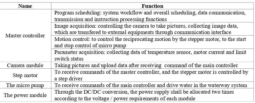
[image:4.612.201.412.380.488.2]For the electronic system, the controller uses STM32 processor as the control core, which is composed of a power module, a communication module, two cameras, two limit switches, two mechanical limit switchs, a DC step motor, a micro pump, four temperature sensors and so on, as shown in figure 5.
Figure 5. Constitution of the electronic system.
Four temperature sensors are used to monitor the important parts of the device, which are respectively located on the bottom board of the device, the motor, the micro pump and the controller. The main functional descriptions of each electronic modules are shown in table 2.
Table 2. Introduction of main parts of control system.
Name Function
Master controller
Program scheduling: system workflow and overall scheduling, data communication, transmission and instruction processing functions
Image acquisition: controlling the camera to take pictures, collecting image data, which are transfered to external equipments through communication interface Motion control: to control the reciprocating motion by the stepper motor, to the start and stop control of micro pump
Parameter acquisition: collecting data of temperature sensor, motor current and limit switch status
[image:4.612.97.519.568.739.2]For the software system, the application program of the control system is written in C language, and the working flow of the device is defined. The program in the controller will automatically run after the device is powered on and work autonomously to complete the process of data acquisition and testing. All the data during the process can be transmitted to the external through the communication interface for monitoring and analysis. The software framework is designed as shown in figure 6.
Figure 6. Program flow diagram.
Experiments
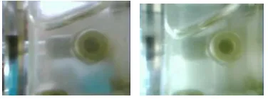
In order to verify the experiment results, it is necessary to study on the early experiments on the ground first [1]. The big bubble gathered floats in the waterway has an irregular shape because of the influence of gravity. Therefore, the device is placed one side tilt in the simulation experiment, as shown in figure 7, making a large number of small bubbles gather at the corner of the bubble trap into a big one. The shape of the gathered bubble is just like a triangular prism, which is very convenient to calculate the volume of a bubble by measurement.
Figure 7. Experiment on the ground. The formula of bubble volume V (mL) is:
V=S*h (2) Where S is the triangular area (cm^2); h is the inside diameter of the bubble trap (cm).
[image:5.612.251.361.458.561.2]
Figure 8. Photo graphs on the ground.
Q (ml/time) = ((V2- V1) / n) / 1000 = 0.002 (ml/time).
The test result is similar to the true value of product indicator. The correctness of measurement is verified to the automatic experiment device.
Table 3 shows the data and results of calculation by image processing. Table 3. Data and results of calculation by image processing.
margin Ref b(mm) Ref a(mm) Measured x(mm) y=x*a/b (mm) V=L*B*H/2 (mm^3)
L 66 28 20 8.48
V1=537.21
B 18 4 57 12.67
H 25 10 25 10
L 66 28 25 10.61 V2=624.93
B 18 4 53 11.78
H 25 10 25 10
Conclusion
In this paper, an automatic measurement device is designed and developed. Automatic tests and indicator measurement are achieved by unmanned operation. A method of calculating the volume of bubbles by image processing is designed, and the product indicators are measured by a number of reciprocation movements. Meanwhile, the reliability of the actual application of the water couple is verified by the experiments, which has laid a foundation for subsequent development and application for research of space science.
In the future, we will improve the performance of the water coupling product by optimizing the design parameters and increasing the number of test times in order to make a large amount of water coupling products used in the air and liquid circulation system in space experiment.
We can also take full advantage of this unmanned automation device for the student-oriented application of space teaching in the environment of space microgravity, which can help deepen understanding of the characteristics of gas-liquid two-phase flow pattern and the action principle of liquid surface tension under weightlessness conditions.
References