DESIGNING AN EMBEDDED COMMUNICATION AID FOR
SPEECH IMPAIRED USING XBEE AND GSM
1V. RAMYA, 2B. PALLANIAPPAN
1
Assist prof., Department of CSE, Annamalai University, Annamalai Nagar. Department of CSE, Annamalai University, Annamalai Nagar.
E-mail: [email protected] , [email protected]
ABSTRACT
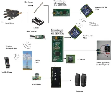
The speech impaired communicates with normal people in everyday life and they use sign language for communication, but they find difficulty in communicating with others who do not understand sign language. And often they need a support for effective communication and this work aimed to lower this barrier in communication. It is based on the need of developing an electronic device that can translate sign language into speech and text, in order to make the communication take place between the mute communities with the general public. Most of the existing systems are image based gesture recognition system and hence highly expensive, whereas this work has developed a low cost Glove based system. The developed system is a complete portable communication aid for the speech impaired which includes converting the sign language in to speech and text, sending the same as message through GSM and controlling the home appliances through hand gesture. In which a hand glove with a 3 axis MEMS and Flex sensor is connected to the ADC channels of the LPC 2138 Microcontroller (M1). The output values from the MEMS and Flex sensor are transmitted to another LPC 2138 microcontroller (M2) at the receiver section through the XBee module. At the receiver section there are two modes namely, teach and play mode and the desired mode is selected through the switch, which is interfaced with the microcontroller. The first mode is the teach mode, in which the microcontroller stores the sign values in EEPROM corresponding to a letter or word, along with an address and the corresponding voice is recorded in voice IC (APR6016). The second one is the play mode, in which the microcontroller recognizes the sign for the corresponding letter/word and plays back the sound values from the voice IC. The letter or word is then displayed on the LCD and a SMS (Short Message Service) is sent through the GSM modem. The device connected to the relay can be turned ON / OFF as per the sign values stored in the teach mode.is the teach mode, in which the microcontroller stores the sign values in EEPROM corresponding to a letter or word, along with an address and the corresponding voice is recorded in voice IC (APR6016). The second one is the play mode, in which the microcontroller recognizes the sign for the corresponding letter/word and plays back the sound values from the voice IC. The letter or word is then displayed on the LCD and a SMS (Short Message Service) is sent through the GSM modem. The device connected to the relay can be turned ON / OFF as per the sign values stored in the teach mode.
Keywords: APR6016; ASL; Communication aid; GSM; MEMS; XBee
1. INTRODUCTION
This paper focuses on developing an aid for speech impaired and physically impaired, who can control the home appliance through hand gesture. The proposed system presents a design and working of a hand-gesture based interface for facilitating communication among speech impaired with the normal people using Handheld Device instead of PC. The system considers only single handed gestures and converts the sign language into voice, which could be heard by the visually impaired and normal people (Bhavina Patel, December 2011). For demonstrating the practical use of the
instead of PC (Fig. 1). And this system is a user dependent system in which the voice IC is trained by the individual, who will be using the system and also we can train and assign any other sign languages (ISL- Indian sign language, ASL- Arabian sign language, ISL- Irish sign language) (A.M. Riad, Feb 2012).
Figure 1: Overall System Architecture of the Proposed System
2. SYSTEM DESIGN
[image:2.595.312.500.536.693.2]Embedded computing systems often involve the design of hardware as well as software. Even if we dint design a board, we may be selecting boards and plugging together multiple hardware components as well as writing code. Fig. 2 shows a design methodology for a combined hardware/software project. Front-end activities such as specification and architecture simultaneously consider hardware and software aspects. Similarly, back-end integration and testing consider the entire system. In the middle, however, development of hardware and software components can go on relatively independently while testing of one will require stubs of the other, most of the hardware and software work can proceed relatively independently (Aparna P, March 2012). The proposed system is designed based on this methodology in which the requirement and specifications are first clearly specified and then the hardware and software design of the communication aid is designed. The hardware architecture is shown in Fig. 3.
Figure 2: A Simple Hardware/Software Co-Design
Methodology.
3.HARDWARE DESCRIPTIONS
3.1ARM7(LPC2138) PROCESSOR:
The LPC2138 micro controllers are based on a 32 bit ARM7TDMI-S™ CPU with real-time emulation and embedded trace support, that combines the 64 kB of embedded high speed Flash memory. Due to their tiny size and low power consumption, these micro controllers are ideal for applications where miniaturization is a key requirement. With a wide range of serial communications interfaces and on-chip SRAM options of 32 kB, is well suited for this system development. Various 32-bit timers, single or dual 10-bit 8 channel ADC(s), 10-bit DAC, PWM channels and 47 GPIO lines with up to nine edge or level sensitive external interrupt pins make these microcontrollers particularly suitable for portable applications (Ata-Ur-Rehman, 2008).
3.2 Flex Sensor
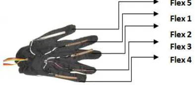
Flex sensor is a unique component that changes resistance when bent. A flex sensor has a nominal resistance of 10k ohms. They convert the change in bend to electrical resistance the more the bend, more the resistance value. The sensors in the Data Glove are optical fibers that are scratched near the bending joint [Hans W. Guesgen, 2012]. The flex sensor value will be a changing one due to the hand movement and vibrations on displaying the hand sign. And hence in the received flex sensor value +/- 20 (optional) is considered to get the constant value for the given sign. In this work the size of the flex sensor used (Fig. 4a and 4b) FLX -01-L is1k to 20 k ohm (Flex sensor).
Fig. 4(A). Flex Sensor FLX -01-L
Figure 4(B): Flex Sensor at the Hand Glove
3.3 XBee Module
XBee is a low-cost, low-power, wireless mesh networking standard. The IEEE 802.15.4 supports frequency range 2.400-2.484GHz and can communicate at speed of up to 250 kbps while physically separated by distances of up to 50 meters in typical circumstances and greater distances in an ideal environment. XBee multipoint RF modules (Fig. 6a and 6b) are ideal for applications requiring low latency and predictable communication timing and providing quick, robust communication in point-to-point, peer-to-peer, and multipoint/star configurations (John Foster, April 2011). The
[image:3.595.307.528.165.246.2]proposed system is a wireless communication aid using XBee and is shown in Fig. 5.
Figure 5: Xbee Communication between Transmitter and Receiver
Figure 6(a): Xbee Module
Figure 6(B): Interfacing diagram for XBEE Module
3.4 GSM-SIM 900
GSM (Fig. 7a) digitizes and compresses data, then sends it down a channel with two other streams of user data, each in its own time slot. It operates at either the 900 MHz or 1800 MHz frequency band. The modem needed only 3 wires (Tx, Rx, GND) except Power supply (Fig. 7b) to interface with Microcontroller/Host PC. SIM900 is designed with power saving technique so that the current consumption is as low as 1.5mA in sleep mode. SIM900 is integrated with TCP/IP protocol [MANISHA PATIL, MANASI M. PATIL
[image:3.595.350.464.427.540.2] [image:3.595.89.286.454.540.2]GPRS through simple AT commands (SIM-AT, (December 2010).
Figure 7(a): GSM Module
[image:4.595.308.505.409.564.2]Figure 7(B): Interfacing diagram for GSM
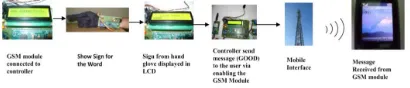
Figure 8: Sending message through GSM
3.5 APR 6016
The APR6016 offers non-volatile storage of voice and/or data in advanced multi level Flash memory, up to 16 minutes of audio recording and playback can be accommodated. A maximum of 30K bits of digital data can be stored. Devices can be cascaded for longer duration recording or greater digital storage. Device control is accomplished through an industry standard SPI interface that allows a microcontroller to manage message recording and playback (Fig. 9). Each memory cell can typically store 256 voltage levels (APR6016 (May 2002). Microphone is a hardware device that is used to store the analog data into APR. Headphone is also a hardware device that is used to retrieve the audio signals from APR.
• Recording Audio Data
The REC command instructs the APR6016 to continue recording in the sector immediately
following the current sector. When the first sector is full the device automatically jumps to the next sector and returns the SAC signal to a high state to indicate that the second sector is now being used. When a SET_REC or REC command is issued the device will begin sampling and storing the data present on ANAIN+ and ANAIN- to the specified sector (APR6016 (May 2002). Any command received after the SAC returns high will be queued up and executed during the next SAC cycle.
• Playing Back Audio Data
The PLAY command instructs the APR6016 to continue playback of the sector immediately following the current sector. When the first sector has been played back the device jumps to the next sector and returns the SAC signal to a high state to indicate that the second sector is now being played (APR6016 (May 2002). When a SET_PLAY or PLAY command is issued the device will begin sampling the data in the specified sector and produce a resultant output on the AUDOUT, ANAOUT-, and ANAOUT+ pins.
Figure 9: Interfacing the Microphone, Op-Amp and APR with the Processor
3.6 EEPROM
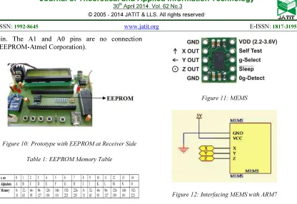
[image:4.595.88.293.420.464.2]pin. The A1 and A0 pins are no connection (EEPROM-Atmel Corporation).
Figure 10: Prototype with EEPROM at Receiver Side
Table 1: EEPROM Memory Table
Assigning the alphabets and symbols in the EEPROM memory is shown in the table 1 and it totally requires the memory of 1020 bits (1k). The 1k memory is divided in to 4 quadrants, in the first quadrant (255 each); the first eight alphabets were stored and for each alphabet 32 bit memory is assigned. Similarly the second and third quadrant were assigned and in the fourth quadrant the remaining characters Y, Z and symbols SP, BSP and OK were assigned.
3.7 MEMS
A micro electro mechanical system (MEMS) is the technology of very small mechanical devices driven by electricity. MEMS devices generally range in size from 20 micrometers (20 millionths of a meter) to a millimeter. They provide multi axis sensing and more accurate data. MEMS can detect acceleration, inclination and vibration by measuring the motion in x, y and z directions simultaneously
(MEMS, April 2008). The MMA7361L (Fig. 11) is used, which is a low power, low profile capacitive micro-machined accelerometer which includes a Sleep Mode that makes it ideal for handheld battery powered electronics [Dr. Krishna Mohanta, 2013]. The g-Select feature allows for the selection between two sensitivities.
[image:5.595.92.508.78.364.2]Figure 11: MEMS
Figure 12: Interfacing MEMS with ARM7
The g-Select pin can be left unconnected for applications requiring only 1.5g sensitivity as the device has an internal pull-down to keep it at that sensitivity (800mV/g)). The proposed system uses 1.5g g-range. The sensor offers a 0g-Detect feature that provides a logic high signal when all three axes are at 0g (MEMS, April 2008). This feature enables the application of Linear Freefall protection if the signal is connected to an interrupt pin or a poled I/O pins on a microcontroller (Fig. 12).
4.SOFTWAREDESCRIPTIONS
or ISP handler is made. If P0.14 is sampled LOW and the watchdog overflow flag is set, the external hardware request to start the ISP command handler is ignored. If there is no request for the ISP command handler execution (P0.14 is sampled HIGH after reset), a search is made for a valid user program. Pin P0.14 is used as hardware request for ISP and requires special attention, since P0.14 is in high impedance mode after reset. Some of the main code in Transmitter side (Hand Glove) and Receiver side is given below.
5.RESULTSANDDISCUSSION
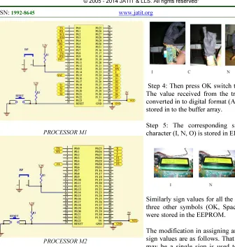
The proposed system is a very good communication aid for the speech impaired and also for the old people or patients who were affected with partial paralytic and unable to speak properly. The Hand Glove (Fig. 14) worn by the person senses the hand
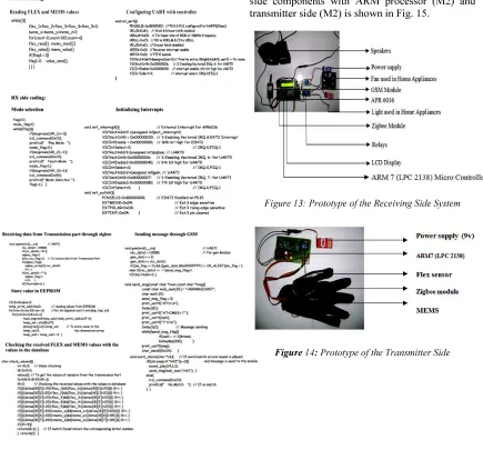
[image:6.595.80.515.266.671.2]movement (sign language) through flex sensors and MEMS and then stored in the transmitter side (Hand Glove) processor’s (M1) memory (Fig. 15). The sign language is transmitted to the receiver side system wirelessly through XBee. Then the receiver side system (Fig. 13) converts the sign language in to text (LCD) and voice (APR6016) and also sends a SMS to the authorized person through GSM module. Hence this system supports the speech impaired, old age people and partially paralytic patients can communicate with their remote relatives and friends easily. Interfacing receiver side components with ARM processor (M2) and transmitter side (M2) is shown in Fig. 15.
Figure 13: Prototype of the Receiving Side System
[image:6.595.310.518.291.431.2]PROCESSOR M1
[image:7.595.96.432.97.450.2]PROCESSOR M2
Figure 15: Interfacing Receiver and Transmitter Side Components with Processor M2 and M1
5.1 Teach Mode
• Teaching the sign values:
The developed prototype assigns and trains the standard sign language (ASL) and the system also supports the modification in assigning and training the new sign values according to our convenience. The following steps explain the procedure for teaching the sign values.
Step 1: Select the mode for teaching the sign values
Step 2: Select the alphabet from the EEPROM – Letter ‘I’
Step 3: Show the sign for the character (for example I, C, N, O) using Hand glove (ASL)
Step 4: Then press OK switch to confirm the sign. The value received from the transmitter XBee, is converted in to digital format (ADC) and the data is stored in to the buffer array.
Step 5: The corresponding sign value for the character (I, N, O) is stored in EEPROM
Similarly sign values for all the other alphabets and three other symbols (OK, Space, and Backspace) were stored in the EEPROM.
The modification in assigning and training the new sign values are as follows. That is the modification may be a single sign is used to denote the entire word. Suppose if we want to switch ON the FAN then show the index finger up to denote the word FAN and point the index finger to denote the word TV. For ON and OFF up and thumbs-down sign may be used.
Example:
• Teaching the sound values:
Step 1: Select the mode for teaching the sound values
Step 2: Select the alphabet from the EEPROM – Letter ‘A’
Step 4: Record the voice (sound) for the alphabet ‘A’ in APR6016 through SET_REC or REC command then the device will begin sampling and storing the data present on the specified sector.
Step 5: The APR starts the count (for alphabet=5sec and for word=10sec) for storing the sound value in the APR.
[image:8.595.93.288.269.352.2]Step 6: Sound value is assigned for the character and word.
Figure 16: Teaching the Sound Values
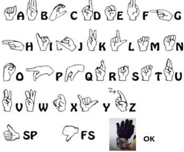
In teach mode, we have to assign the values (sign) for 26 alphabets (A to Z) and three symbols (OK, Space, Backspace). All these values are stored in EEPROM and each symbol needs 64 bits (8 bytes), Five bytes for the five flex sensors and 3 bytes for the 3 MEMS (x, y, z axis). These eight values combine to form a symbol (sign). Similarly the voice has been recorded for the alphabets and ten words in the APR6016 (Fig. 16). The American Sign Language (ASL) is used in this proposed system which is shown in Fig. 17. In addition to 26 alphabets and two symbols (SP, FS) one more symbol (OK) is added in our sign language to confirm the end of the each word.
Figure 17: American Sign Language (ASL)
5.2 Play Mode
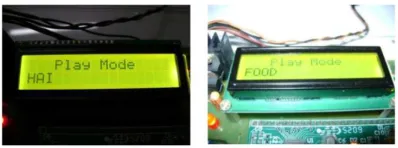
[image:8.595.306.509.386.497.2]In the play mode the receiver reads the values from hand glove (transmitter). The five flex sensor values and three MEMS values are send to the receiver module for hundred times, then the average of these hundred values were calculated and compared with the values assigned in the EEPROM. The flex sensor value (change in resistance) will be changing due to the vibrations and hand movements during displaying the sign. When comparing the values in the EEPROM ± 20 is added with the each of the received flex sensor’s values to get the constant value for the given sign which is shown in the coding (step 2). After completion of an entire word then show OK symbol. The word displayed in the LCD is compared with the words in the coding, if the word matches then play back the corresponding sound from the APR and send to the GSM module (Fig. 18). The GSM module forwards this word to the mobile which is the predefined number (step 8).
Figure 18: Play Mode Process
• Playing back the recorded sound values
Step 1: First check the connectivity of the GSM modem.
Step 2: If the connection is done then the LCD displays the message ‘MODEM connected’ otherwise it displays ‘MODEM error’.
[image:8.595.95.283.558.714.2]The flex and MEMS values for the each and every given sign (H A I) is read for 100 times from the hand glove and it is stored in the buffer memory which is shown in table 1. The controller takes the average of it and compares it with the values assigned in the EEPROM Memory Table. If the value matches then the APR play back the recorded sound value the corresponding sign.
Step 4: The LCD displays the corresponding word for each and every sign showed.
Step 5: Then show the OK symbol to confirm the word
[image:9.595.90.289.413.487.2]Step 6: IF the word doesn’t match with predefined word then the LCD diplays ‘NO MATCH’.
Figure 19: Word No Match
Step 7: The correspondind sound will play back using SET_PLAY or PLAY command, then the device will begin sampling the data in the specified sector and produce a resultant output on the AUDOUT, ANAOUT-, and ANAOUT+ pins.
Step 8: The GSM sends the same word (HAI) as SMS to the predefined number
• Controlling the appliances
Step 1: Show the sign for controlling the appliances. For demonstration purpose, there are two appliances (TV and Fan-ON/OFF) were controlled through the sign language.
Step 2: Then Show OK symbol to confirm the word Step 3: The LCD displays the corresponding word for the sign showed
Step 4: The corresponding voice will be play back through the speaker
Step 5: Switch ON the relay to control the appliance (FAN ON)
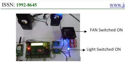
[image:9.595.94.503.550.740.2]The home appliances like FAN, TV and lights etc., are also be controlled through the sign language (Fig. 20). The receiver processor (M2) process the sign language and controls the appliance through relays. At present the system is designed to convert the sign language in to text and speech for only few words for the sake of demonstration and the system also supports to store more words in future.
Figure 21:Prototype of the Proposed Systems Shows the Appliances Switched ON
6.CONCLUSION
To alleviate the communication problem among speech-impaired people, an assistive technology that will provide a more convenient and less time consuming means of communication is required. Hence a wireless transceiver communication aid is developed for recognizing the signs and then converted into speech and text. The assistive aid that is developed resulted in providing a user friendly approach to the speech impaired people. Speech impairment refers to the inability to produce normal speech. The user dependent system approximately provides 90 percent accuracy. This system helps the speech impaired people and for the bed-ridden, paralytic patients to express their need and announce their requirements through sending a message to their friends and relatives. This system also controls the home appliances (ON/OFF) through the hand signals. The system is designed using ARM7 LPC2138 processor, which provides the best performance to the user. The flex sensor and MEMS values are sent to the receiver station and the receiver station checks the conditions for performing some actions that may be text or voice. There are two modes in the proposed system, they are play mode and teach mode. In teach mode, the sign and sound values are trained and stored. The sound values were recorded using APR6016 integrated circuit within 5 sec of time interval for an alphabet and 10 sec for a word. The device supports both random and sequential access of the multiple messages. The sample rates are user-selectable; allowing designers to customize their design offers, true single-chip voice recording, non-volatile storage and playback capability for 16 minutes. In the Play mode, the predefined sign values are converted in to the speech and text, and also sent as an SMS to the remote people. The play mode also controls the home appliances according to the given sign. The difficulty encountered in this work is, recognizing the hand gestures for similar signs like R and S, also C and O. Hence we need to get the proper MEMS value so as to assure the sign.
It needs proper training for assigning the sign values.
REFRENCES:
[1] A.M. Riad , Hamdy K.Elmonier, Samaa.M.Shohieb, and A.S. Asem “Signsworld; Deeping Into The Silence World And Hearing Its Signs (State Of The Art)”, (IJCSIT) Volume 4, Number1, Feb 2012.
[2] Aparna P, Mohana priya P, Usha Rani T, Jeba Jaculin B, Pradeep Raja B, “Development of an Assistive Aid for Speech Impaired”, International Journal of Scientific and Research Publications, Volume 2, Issue 3, March 2012.
[3] Ata-Ur-Rehman, Salman Afghani, Muhammad Akmal, Raheel Yousaf, “Microcontroller and Sensors Based Gesture Vocalizer”, ISPRA '08, 2008. [4] Bhavina Patel, Vandana Shah, Ravindra
Kshirsagar, “Microcontroller Based Gesture Recognition System for the Handicap People” JERS/Vol. II/ Issue IV, December 2011.
[5] APR6016, Datasheet, Voice Recording and Playback Device, Aplus Integrated Circuits Inc.
[6] EEPROM-Atmel Corporation 0180Z1– SEEPR–5/07, May 2002.
[7] Flex sensor-Spectrasymbol.com (888) 795-2283 Rev A2 - Page 1-2.
[8] John Foster, XBee Cookbook Issue 1.4 for Series 1 (Freescale) with 802.15.4 Firmware, April 2011.
[9] MEMS, Freescale Semiconductor Technical Data, Document Number: MMA7361L, April 2008.
[10]Shoaib Ahmed .V, “Magic Gloves (Hand Gesture Recognition and Voice Conversion System for Differentially Able Dumb People)”, Submitted to: Tech Expo-The Global Summit, London 2012, December 2012.
[11]SIM-AT, command Manual-V1.03, December 2010.
Proceedings of the Twenty-Fifth International Florida Artificial Intelligence Research Society Conference,2012,pg no. 353-368.
[13]Dr. Krishna Mohanta and Dr.V.Khanaa,” Assistive Devices For Service Members With Disabilitie”, International Journal Of Advanced Research (2013), Volume 1, Issue 9, pg no. 548-553.