2017 International Conference on Computer, Electronics and Communication Engineering (CECE 2017) ISBN: 978-1-60595-476-9
The Redundancy Technology of Measurement and Control Function
of the Smart Substation
Zhen YANG
1,*, Yan-ru ZHAO
1, Jun-peng HU
2, Hong-bing SHEN
1and Ji-feng WEN
31China Electric Power Research Institute, Beijing, China, 100192
2State Grid Shandong Electric Power Company, Jinan, China,250001
3Nanjing Nari Relays Electric Co., Ltd. Nanjing, China, 211100
*Corresponding author
Keywords: Smart substation, Station level, Functional redundancy in measurement and control, Uniqueness, Central control servers.
Abstract. In order to improve construction economy and system reliability of smart substations, this paper presents an application model of functional redundancy in measurement and control. Puts forward effectiveness identification of data monitor direction in measurement and control functional redundancy, verification of dual monitor, principle of control direction mutex and uniqueness. Makes clear the structure of hardware system, analysis its key technology and realization method. In this method, the central control servers are established in station level. Solves the problems of remote information selection, control authority uniqueness and poor data sharing caused by measure-control devices redundancy configuration according to voltage level in substations. Reduces the numbers of secondary cubicles and interfaces, improves integration of secondary equipment.
Introduction
Now, in the smart substations of China, measurement and control functions of the original single configuration is “doubled” because of application of the protection measurement and control integration device[1] and the centralized type measurement and control device in the current smart substation, which causes functional redundancy in measurement and control. Functional redundancy in measurement and control will cause uniqueness of monitoring information and control object of the primary electrical equipment’s etc realistic problems. In order to solve functional data redundancy in measurement and control and apply redundancy data better, this paper analyzed
effectiveness identification of redundancy data monitoring direction in measurement and control,
double monitoring calibration, and mutual exclusiveness and uniqueness principles are forwarded in
theory, and key technology and realization method of redundancy application model in
measurement and control in theory.
Study on Functional Redundancy Technology Concept of Functional Redundancy
Redundancy means repeating configuration of some components in the system. When fault occurs in the system, the component which is configured redundantly is accessed and takes over working of the fault component, and then fault time and fault rate of the system are reduced. The general designed redundancy ways include CPU redundancy, power supply redundancy. Some systems will consider whole system redundancy under extreme conditions, which also include I/O redundancy.
Redundancy Technology of System
actively, it requests that redundancy node can inspect operation status of the master and standby nodes automatically; it is automatically switched to the standby node when the master node fails. Passive redundancy means it will be switched to the standby component when the component in service fails or is abnormal.
Data Effectiveness Identification at Monitoring Direction and Study on Calibration Method Study on Data Identification Plan of Substation
Processing of the current smart substation on redundancy monitoring data is classified as data identification of station level and spacer level according to processing, signal data collection of the substation is uploaded to the station level processing centre after data processing in the spacer level, which are finally shown to the operation person through the system backstage and the data communication gateway machine in the system.
Data Identification of Station Level. Data identification of the monitoring master machine in the station level mainly complete processing and analysis of redundancy data by the station level, and corresponding effective data are forwarded according to relevant regulations, which reflects correct monitoring data to operation person.
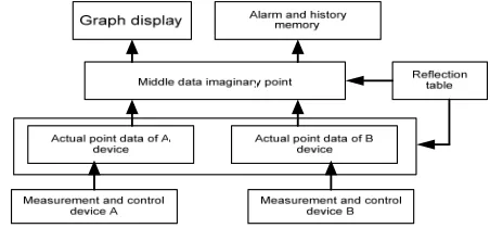
This method applies strategy with imaginary point reflecting double actual measurement and control data and realizes accessing of the double measurement and control data, i.e., provide a layer of spacer level which will separate this device from the double measurement and control device, and ensures information of the electrical primary device concerned by the operation person unique. Actual physical information of the electrical primary device is collected by the double measurement and control devices and transmitted to the system. The double redundancy information is actual point data in the system. The so-called imaginary point data are data not corresponding to the measurement and control device when they are compared to actual data information.
One measurement and control device of the double measurement and control devices is defined
as current main data source[2] during operation process through switching of the device, imaginary
[image:2.612.191.417.496.601.2]point selects actual point information of the main data source device in the reflection relationship record to correspond. Remote measurement and remote signal actual point data of the main data source device are assigned value to corresponding imaginary point data. Principle schematic figure of the substation which station level realizes double measurement and control data access is shown as figure .
Figure 1. Schematic of Double Measurement and Control Sets accessing.
Data Identification of Spacer Level. Data identification of the spacer level mainly determines effectiveness of data between redundancy measurement and control of the spacer level in combination with sampling, operation status and communication status etc. of analogue quantity, and which is uploaded to the station level.
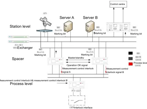
[image:3.612.186.424.195.372.2]Redundancy of measurement and control function of the substation is realized when configuration of the equipment in the station level is reduced as possible. The measurement and control device applies operation models with the primary and standby for upper machine and double primary for lower, two sets of measurement and control functions are independent completely. Structure of the substation system under data identification conditions of the spacer level is shown as figure 2.
Figure 2. Structure of system architecture of substation in the condition of Data Identification in Spacer Level.
The measurement and control logic device provides “local machine interlock” and “local machine primary and standby” two hard interface switching out in hardware[4]. When the master CPU or IO board card of this device can’t maintain normal monitoring of the substation, interlock abnormal signal is output and the “local machine interlock” signal relay is driven to output. Program drives the “local machine primary and standby” signal relay according to current primary and standby status of the device. When the local machine is primary machine, this interface is closed, and another set of the measurement and control logic device is informed.
In software, measurement and control interaction interacts individual communication link circuit status between two measurement and control, whether timing of the device is good and whether quality information of the corresponding control block is normal etc. and interacts with measurement and control at opposite side through communication link circuit.
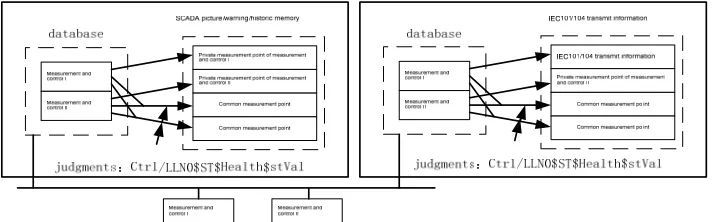
After the measurement and control device determines respective primary and standby[5], this status is operation status featuring measurement and control of the protection measurement and control integration device, which is uploaded to the device in the station level through LN0$ST$Health$stVal marking in the measurement and control logic device (LogicDevice: CTRL_PUB) in the IEC61850 model. Double measurement and control working models are shown as figure 3.
Control centre
Station level
Server A Server B
Marking bit
Marking bit
Marking bit
Marking bit Marking bit
Exchanger
Spacer
Process level
Master/standby
Operation OK signal
Measurement control interlock signal A
Measurement control interlock signal B
Measurement control interlock A& measurement control interlock B
Process level
Figure 3. The Mode of Double Measurement and Control Sets.
Data processing method of the multiple sources between the station level and the spacer level are described respectively in above. For data identification of the station level, its advantage is that regulation on data identification is basically concentrated on the station level system, and processing standard is uniform; main advantage of data identification method of the spacer level is that the measurement and control device can identify certain accuracy of data according to own operation status and real-time collection conditions.
In combination with data identification of the spacer level and the station level two levels, identification and application of the double data source for double measurement and control in the smart substation is realized well through above method analysis according to characteristics of different data source.
Data Calibration Plan of Substation
Data quality means identification of abnormal data before data loading and data preposition and rejection of wrong data. Data quality will restrain correlation relationship of data from correction, integrity, uniformity, effectiveness and self-consistency five aspects, data must meet with correlation relationship between data, and which shall not be contradict each other. In order to make operation person of the substation can master operation data of the substation accurately and completely, the data calibration module shall be imported to judge abnormal data automatically and send out alarm according to importance degree, it will greatly improve data confidence of the automation system in the station level substation and it will also greatly improve quality of the data source in the data centre.
In case of measurement and control function redundancy system, following data calibration methods are forwarded in order to ensure relative effectiveness of data of the substation.
[image:4.612.129.485.74.185.2](1) Data calibration based on double data sources. Compare information of the primary collected by the double system mutually. if data are consistent, it is considered that data are true and effective. Comparison regulation based on the multiple data source method is shown as table 1.
Table 1. Comparison regulation based on multiple data source method.
Quality consistent and effective Quality consistent and
ineffective Quality not consistent
Data consistent Data stored in database/backstage show Data rejected and warm Selection quality stored database effectively and show
Data not consistent Calibration of lower level Data rejected and warm Selection quality stored effectively and show
(2) Calibration method based on statistic. Judgment basis whether data point is abnormal is to check whether it is in accordance with former statistic rules.
It isn’t difficult to learn through above data calibration method that data calibration method of the double data sources is applicable to data calibration of the substation.
Mutual Exclusiveness and Uniqueness Study at Control Direction
Remote control command in the substation mainly comes from the dispatch master station and the system backstage in the substation. When measurement and control are redundantly configured, hardware between the measurement and control devices and models are not consistent, and it is difficult to realize interaction between remote control commands, uniqueness of the control right in the spacer level is destructed. Following plans are forwarded in order to ensure uniqueness of control right in the spacer level.
(1) Interaction method of station level
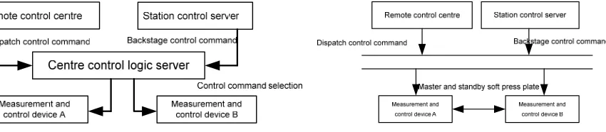
[image:5.612.105.530.277.370.2]Interaction method of station level is to establish a set of centre control server in the station level, control command between the station level and the system backstage is distributed through this server, and then ensure uniqueness of control command of the dispatch master station and the station level. Shown as figure 4.
Figure 4. the Uniqueness of Control commands. Figure 5. Interactive method in Spacer Level.
Seen from the figure, control command of the interaction method in the station level is down mode. When the dispatch or system backstage of the station level sends out remote control command under this way, it is distributed via the centre control logic server. This centre control logic server isn’t a physical entity, it may be a logic device existing in the dispatch master station or preposition of the station level, its function is to receive and transmit remote control command sent out from the equipment in the station level. Belonging of central control right of the equipment in the station level is implemented through the centre control server, the measurement and control device in the spacer isn’t classified as primary and standby, and it responds remote control command at same time, and then realize uniqueness of the remote and system backstage on control right of the primary electrical equipment in the substation under remote status.
(2) Interaction method of spacer level
Interaction method of the spacer level realizes switching of control right through setting the primary and standby soft press plates at equipment side. Uniqueness of control right is determined through the soft press plate of the measurement and control device at this way. Control command of the system backstage in the station level is carried out through the device taking control right as primary under remote status. Any one unit of the measurement and control device has no primary and standby remote control under local status, any one unit of the measurement and control device can respond local control command. Shown as figure 5.
Conclusion
This paper forwards effectiveness identification at data monitoring direction for measurement and control function redundancy, calibration of double monitoring, mutual exclusiveness and uniqueness principle at control direction and recommended optimum plan through analysis and study of measurement and control function redundancy of the smart substation, which specifies constitution of the hardware system and analyzes its key technology and realization method. It provides theoretical basis for realization way of measurement and control function redundancy at each voltage class in the smart substation. In research of this paper, the smart substation which protection device is installed locally is redundantly configured with the measurement and control device according to voltage class[6], which completes measurement, control and operation of all spacers at each voltage class; It solves the problem that whole voltage class measurement and control of one measurement and control device are invalid at inspection status. Redundant application of the measurement and control device reduces quantity of the secondary panel and cabinet greatly, it can save land occupation, reduce investment cost and reduce operation and maintenance working quantity. And it can also improve operation safety and reliability of the substation.
References
[1] Liu Zhenya. General design of power transmission and transformation engineering in smart grid corporate 110(66)~750kV smart substation part [M]. Beijing, China Power Press, 2011: 99-100. [2] State grid corporate. Construction technology of smart substation [M]. Beijing, China power press, 2010: 151-153.
[3] Song Kang, Yuan Kejun, Ren Zhenxing, He Liang. Remote double control realization method of digital smart substation[J]. Power automation equipment, 2012, 32(7): 140-142.
[4] Zhong Lianhong, Liang Yixian. Technology and application of smart substation [M]. Beijing. China power press, 2010: 90-94.
[5] Hu Shaoqian, Xiong Muwen, Wang Wenlong. Double control realization plan discussion of digital substation [J]. Guangdong Electric Power, 2011, 24(10): 45-47.