University of Huddersfield Repository
Arif, Shahab
Electronic Braille Document Reader
Original Citation
Arif, Shahab (2013) Electronic Braille Document Reader. Masters thesis, University of
Huddersfield.
This version is available at http://eprints.hud.ac.uk/id/eprint/18089/
The University Repository is a digital collection of the research output of the
University, available on Open Access. Copyright and Moral Rights for the items
on this site are retained by the individual author and/or other copyright owners.
Users may access full items free of charge; copies of full text items generally
can be reproduced, displayed or performed and given to third parties in any
format or medium for personal research or study, educational or notforprofit
purposes without prior permission or charge, provided:
•
The authors, title and full bibliographic details is credited in any copy;
•
A hyperlink and/or URL is included for the original metadata page; and
•
The content is not changed in any way.
UNIVERSITY OF HUDDERSFIELD
Electronic Braille Document Reader
Abstract
An investigation was conducted into developing a portable Braille device which would allow visually impaired individuals to read electronic documents by actuating Braille text on a finger. Braille books tend to be bulky in size due to the minimum size requirements for each Braille cell. E-books can be read in Braille using refreshable Braille displays connected to a computer. However, the refreshable Braille displays are expensive, bulky and are not portable. These factors restrict blind and visually impaired individuals from accessing much of the literature which isn’t available in Braille.
The proposed device overcomes the problem of carrying bulky Braille books by allowing multiple e-books to be saved in a portable memory device. By convert text from Latin characters into Braille patterns, it will give the blind access to books which were never published in Braille. The single Braille cell design reduces the bulk of the device allowing it to be portable and reducing the cost. An additional benefit of the device is that it can be integrated into a glove and worn thus giving the user freedom to carry on with other tasks while reading.
A prototype was developed to prove Braille could be read by actuating Braille characters on a finger. The device read text from an SD card, translated it into Braille characters and actuated the Braille pattern. Blind volunteers proficient in Braille reading were able to decipher the Braille text actuated on the finger after some practice.
iii
Acknowledgements
⠃⠑⠎⠒⠍⠑⠀⠁⠇⠠⠇⠂⠓⠑⠀⠁⠇⠠⠗⠂⠱⠒⠍⠂⠝⠑⠀⠁⠇⠠⠗⠂⠱⠑⠊⠍⠑
مي حر لا نمحر لا الله مس ب
In the name of Allah, Most Gracious, Most Merciful.
All praise be to Allah the most gracious most merciful for all the blessings bestowed upon me and providing me with the knowledge, ability, patience and opportunity to complete my M.Sc. I am extremely grateful for the luxury the almighty has blessed me with and pray he gives me the strength and ability to use all I have in wealth and knowledge for good and attain his pleasure.
I would like to thank my supervisor Dr. Violeta Holmes for all the support and assistant over the years. Without her enthusiasm and encouragement I may not have achieved all that I have. She is the perfect example of what a supervisor should be like and it has been a pleasure working with such a nice person.
I would also like to thank my mum Samina and dad Mohammed Arif for everything they have done for me over the years. Their love, support, encouragement and teachings have enabled me to get this far and become the man I am. They deserve all the credit for the work I have done until now and any work I undertake in the future. Thank you for putting up with all the tantrums, late nights and everything else. My siblings also deserve gratitude as they have always been there for support and guidance. My sisters deserve a special thank you for supporting me financially through the hard times and being there at times of need.
I would like to thank my friend Safwan Dingmar for all the support and help he’s provided over the years. He has always been there to bounce ideas off when required and provide constructive criticism when I’ve gone off the wrong path. He’s been there as a friend and a brother through the years at university and God willing will be for many years to come. A big thank you to Haseeb Kayani and the rest of my wonderful friends who have provided me with abundance happiness, joy and laughter.
Lastly I would like to thank the Islamic society of university of Huddersfield for catering for my spiritual needs and allowing me to gain religious knowledge along with my M.Sc. The ISOC committee has been a great support and organizing events with them through the year provided a perfect way to take my mind off my studies and come back with a fresh mind.
Table of Contents
List of Figures... vi
List of Tables ... viii
1.0 Introduction ... 1
1.1 Aims: ... 1
1.2 Objectives: ... 1
1.3 Scope ... 2
1.4 Background... 3
1.4.1 Braille ... 3
1.4.2 Electronic Braille ... 3
1.5 Consumer survey ... 4
1.6 Dissertation Outline ... 5
2.0 Literature Review ... 6
2.1 Braille ... 6
2.2 Types of Braille ... 7
2.2.1 Six Dot Braille ... 7
2.2.2 Eight Dot Braille ... 7
2.2.3 Grade 1 ... 8
2.2.4 Grade 2 ... 8
2.3 Braille in Different Languages ... 9
2.4 Braille Technology ... 10
2.4.1 Refreshable Braille Displays ... 10
2.4.2 Braille Embossers/Note takers ... 10
2.4.3 Speech Synthesizers ... 10
2.4.4 Dictaphones ... 10
2.5 Overview of technologies suitable for EBDR actuators ... 11
2.5.1 Bi-stable Linear Moving Magnet Actuators ... 11
v
3.1.2 SD Interface ... 22
3.2 Hardware Design ... 25
3.2.1 Actuators ... 25
3.2.2 Drive Electronics ... 30
4.0 System Test ... 32
4.1 Text Processing ... 32
4.2 Actuators... 33
4.3 EBDR ... 33
5.0 Results ... 34
5.1 Text Processing ... 34
5.2 Actuators... 35
5.3 EBDR ... 36
6.0 Discussion... 37
6.1 Text Processing ... 37
6.2 Actuators... 38
6.3 EBDR ... 39
7.0 Conclusion ... 40
8.0 Further Work ... 41
9.0 References ... 42
List of Figures
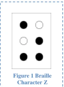
Figure 1 Braille Character Z ... 7
Figure 2 8-dot Braille Character Z ... 7
Figure 3 Quote in Grade 1 Braille [8] ... 8
Figure 4 Quote in Grade 2 Braille [8] ... 8
Figure 5 Example of Arabic Braille ... 9
Figure 6 Example of Chinese Braille ... 9
Figure 8 Diagram explaining the Internals and Functions of a Squiggle Motor [21] ... 12
Figure 7 Squiggle Motor ... 12
Figure 9 Bimorph Actuator [13] ... 13
Figure 10 Flexy Motor ... 14
Figure 11 2 mm Micro motor ... 14
Figure 12 Shape Metal Alloy - Nitinol Wire ... 15
Figure 13 Right Angle Pull/ Simple Lever Examples [27] ... 15
Figure 14 Cross-Sectional illustration of Actuator showing FET, Polymeric Actuator with a semisphere on the tip ... 16
Figure 15 Sheet type Braille Display ... 16
Figure 16 Operation of Bucky-gel Actuator [30] ... 17
Figure 17 Braille Display using Bucky-gel [29]... 17
Figure 18 EBDR flow diagram ... 18
Figure 19 Picture of Arduino Mega 2560 ... 18
Figure 20 Flow Code Diagram ... 19
Figure 21 Braille Pattern ... 19
Figure 22 Braille patterns ... 20
Figure 23 List of characters ... 20
Figure 24 Input text ... 20
Figure 25 Setup outputs ... 21
Figure 26 Main loop ... 21
Figure 27 Adafruit microSD shield [32] ... 22
Figure 28 SD Declarations ... 22
Figure 29 SD Setup ... 23
Figure 30 Initialize SD Card Function ... 23
Figure 31 Read File from SD Card Function ... 24
Figure 32 Nitinol in Series Configuration ... 25
Figure 33 Lever Configuration ... 26
Figure 34 V Configuration ... 26
Figure 35 (A) Relaxed Nitinol (B) Activated Nitinol ... 26
vii
Figure 47 Electronic Braille Document Reader Prototype ... 31
Figure 48 LED Braille module ... 32
Figure 49 PEACE be upon you! 321 in Braille ... 32
Figure 50 Fully Assembled EBDR ... 33
Figure 51 Serial Monitor output – Successful initialization ... 34
Figure 52 Braille Output on LED Braille cell ... 34
Figure 53 Serial Monitor output - Failed initialization ... 34
Figure 54 Actuator Test ... 35
Figure 55 Actuated Braille Text. ... 36
Figure 56 Actuation difference ... 36
List of Tables
Table 1 Characteristics of Bistable Linear Magnetic Actuators ... 11
Table 2 Linear Piezo Specifications ... 12
Table 3 Piezo Ceramic Specifications ... 13
Table 4 Flex Motors Specifications ... 14
Table 5 Nitinol Specifications ... 15
Table 6 FET Polymeric Actuator Specifications ... 16
Table 7 Bucky-gel Actuator Specifications ... 17
Page|1
1.0 Introduction
Blind and visually impaired individuals use a matrix of dots called Braille to read. Currently only a limited number of books get translated in to Braille which requires a human to read and type the entire book in Braille. The books which are translated are bulky due to the minimum size requirement of a Braille cell. The challenge the blind people face is having to source the desired books in Braille and then not being able to carry more than a few because of the large size.
Refreshable Braille displays exist which have a line of Braille cells and can display text from a computer when connected to one. These allow the blind to be able to use computers and access the vast catalogue of literature online. The drawback of these is the phenomenal costs and size of one.
There is a clear need for a device which can overcome these obstacles for the blind. This project looks into the feasibility of designing a device which would allow a blind user to access any digital text document by converting it to Braille and displaying it in a manner suitable for them to read.
1.1
Aims:
An Electronic device capable of reading text from external memory, and translating it from Latin characters to a Braille pattern which can be felt by a user.
1.2
Objectives:
Design a text processing module capable of: o Reading text from external memory o Translating into Braille pattern
Determine the type of Braille to use
Determine the grade of Braille translation o Actuating the pattern on a Braille cell
Design a refreshable Braille cell capable of actuating the Braille pattern o Determine which actuators are capable
1.3 Scope
The Electronic Braille Document Reader (EBDR) will allow the user to read any text in digital form. Users can download any text into the devices memory; whether it’s newspapers or E-books. The EBDR has an advantage over conventional Braille books as it allows the user to read the book using a finger through a glove, while still being able to carry on with other tasks such as walking, housework, etc. Following are the tasks taken to accomplish the aims.
1. Research into which Braille system is best suited for the device. 2. Investigate what is the best way to read Braille.
3. Research into Patents – investigate if there is a need for a patent. Apply for a patent if needed. 4. Talk to a blind person to get design ideas.
5. Research the best way to translate text to Braille.
6. Examine different microcontrollers and figure out the one best suited for the job. 7. Explore ways to move the pins and choose the best.
8. Program microcontroller to read text from external memory and translate to Braille pattern. 9. Design a refreshable Braille cell to allow user to feel the Braille pattern.
10. Program microcontroller to move the pins to represent the text in Braille. 11. Finish prototype.
12. Test prototype with the blind and gather feedback. 13. Improve the prototype according to the feedback. 14. Test prototype with improvements.
Page|3
1.4 Background
1.4.1 Braille
In 1821 a blind Frenchman Louis Braille invented the Braille writing system to help blind people
read and write. Braille consists of a cell of six raised dots arranged in two columns of three dots,
which the user can read by feeling using a finger. The Braille system is used worldwide by blind
people and has also been translated in other languages. [1]
Over time Braille has been adapted to be used with different subject matter e.g. mathematics and
music. As six-dot Braille was adapted to be used in other mediums, it became evident the 64
combinations (with some combinations too similar to be used) were the restricting factor of Braille.
Eventually the six-dot Braille was extended to eight dots with a 4 high and 2 wide cell. The
eight-dot Braille gives a total of 256(2
8) different combinations. All the 256 combinations of the eight-dot
Braille are encoded in Unicode, while the six-dot Braille is usually stored in ASCII Braille. The
advantage of the eight-dot Braille over the six-dot in written text is that a single cell can
differentiate between case, numbers and symbols. [2][3]
1.4.2 Electronic Braille
Many everyday items have been significantly improved with the emergence of electronics. But
these have been insignificant for the blind. Technology has made a contribution to the blind in the
form of refreshable Braille display, which connect to a computer and allow a blind person to read
what’s displayed on the screen. But these haven’t leaped forward much since their invention. The
main downfall of the refreshable Braille Display is the cost of each unit and the bulky size.
Currently the National Institute of Standards and Technology in the US is working on a
rotating-wheel Braille display which allows the user to continually read while keeping the finger stationary.
The rotating wheel design should cut the cost and the size down but it will still cost as much as a
computer. [4]
Braille books are very bulky and are also hard to read without a stable place to rest the book. Only a
fraction of the books published in text are also published in Braille. For the sighted the problem of
lugging around many books was overcome by the invention of the E-book readers. The same can be
done for the blind with the Electronic Braille Document Reader. A blind user can potentially carry
around hundreds of books in a glove. An additional benefit of the Electronic Braille Document
Reader is that it can provide the blind access to the thousands books which are never published in
Braille, by translating regular e-books into Braille.
1.5 Consumer survey
A meeting was arranged at the Society for the Blind of Dewsbury Batley and District with a blind
individual called Janet who was skilled in reading Braille to discuss the systems feasibility of
allowing identification of Braille patterns using one Braille cell actuated on a finger. The
opportunity was also utilized to discuss other aspects which could potentially affect the final
outcome.
Currently available Braille technology was discussed to ascertain whether the Electronic Braille
Document Reader would benefit the blind in anyway. The outcome suggested that the EBDR would
be adding to the market in a unique way by giving the user freedom, which none of the current
products offered. The Braille user, Janet explained the current electronic Braille systems were
constrained to only displaying computers screens and at a cost of as much as a high end personal
computer, it’s not a worthwhile investment for many.
Another point Janet made was that Braille books tend to be big and always require a flat stable
surface to rest while reading by sliding fingers across the page to feel the character patterns. The
EBDR benefits blind by allowing many books to be saved in a relatively compact device which
does not require any input from the user to work. The ease of use also encourages the use of Braille
reading with the young. There are currently many voice synthesizers which can read text out and
dictaphones which can be used for recording notes. But they have drawbacks of their own, which
were explained by the former British home secretary David Blunkett in an article written for the
BBC on the 200
thanniversary of the invention of Braille. Mr Blunkett said that Braille gave him the
ability to make his notes in the House of Commons in privacy. Braille also allowed him to be able
to read notes while still being able to focus on the speeches. [5]
The meeting with Janet also gave a better understanding of how Braille is read. Each Braille dot has
to be a minimum size as too small would be very hard to feel by an average user. Braille can be
written in two forms, Grade I (which is a one to one representation of each letter in Braille) and
Grade II (which is written in short form). Currently 100% accurate text translation to grade II
Braille can only be done by a human and not a machine due to the different meaning of patterns
depending on the context. Janet explained all users of Braille can read grade I Braille, so the
Electronic Braille Reader would not need to use grade II Braille but would be a beneficial addition.
Page|5
1.6 Dissertation Outline
The dissertation is set out in eight main chapters followed by references and appendices.
Chapter 1 Introduction identifies the aims and objectives of the research while also discussing the
background and the motives for the project.
Chapter 2 Literature Review presents an analysis of the Braille system and other technologies
available to the blind. Also presents a review of the technologies available for the development of
the EBDR prototype.
Chapter 3 System Design details the design process involved in the design of the EBDR prototype.
Chapter 4 System Test describes the steps taken to test the prototype.
Chapter 5 Results Presents the results of the tests carried out on the prototype.
Chapter 6 Discussion discusses the outcome of the test results. Also describes the problems
encountered and solutions used to overcome the problems.
Chapter 7 Conclusion presents the outcomes of the research.
Chapter 8 Further Work highlights areas of further investigation and outlines recommendations on
development of the prototype.
Chapter 9 References provides references to literature used in the research.
2.0 Literature Review
2.1 Braille
Tactile forms of reading for the blind have existed since ancient times. As blind people touch and feel objects around them to picture their surroundings their finger tactile receptors get exceptionally well developed. This allows them to be able to feel details sighted people barely notice. Over time blind people have developed ways in which they are able to read using the sense of touch to varied success.[6]
Sighted people have also contributed to the effort by developing tactile systems which allow the blind to read text. Much of the effort was in the form of raised letter in large sizes so the tactile shape of the letter could be felt. These were very slow and difficult methods as they required the reader to trace around the individual character.
Charles Barbier de la Serre who served in the French army as a captain came up with “night writing” a method of writing using dots and dashes which could be read by touch, in response to Napoleon’s demand for a code which would allow for silent communication in the darkness of the battlefield. Unfortunately for Barbier the code proved to be too complicated for the soldiers to decipher with touch alone and was rejected. Barbier later demonstrated his writing system at the Royal Institute for Blind children in Paris where a young Louis Braille studied.[7]
Louis who lost his eyesight due to an accident at the age of 3 was a bright student experimenting with different ways of reading. Louis recognized the advantages the night writing code had over the current reading system available but he also saw the drawbacks and limitations. With Barbier’s code it was impossible for the reader to move swiftly from one character to another due to its large size and it was also limited to 36 basic sounds to make a word instead of the alphabet. Louis decided to develop the system further to provide a viable solution. By the age of 15 in 1824 Louis had improved the system enough to represent the entire alphabet and numbers in a six dot cell the size of a fingertip.[1]
Page|7
Figure 2 8-dot Braille Character Z
2.2 Types of Braille
2.2.1 Six Dot Braille
There are many variation of Braille in existence which could be used for the
Electronic Braille Document Reader (EBDR). The most commonly used
Braille system is the original six-dot Braille, which consists of a cell of six
raised dots arranged in two columns of three dots. The dot positions are
numbered top to bottom 1 to 3 on the first column (left), and 4 to 6 on the
second column (right). Any Braille character can be described using the
positions, e.g. The letter ‘S’
⠎can be described as 2-3-4. The six-dot Braille
has a total of 63 combinations, but some of the combinations feel too similar to
be used e.g.
⠊and
⠔so are omitted. The punctuations are represented by
their own set of patterns. But numbers use the same patterns as the alphabets
‘a’ to ‘j’. They are recognized by the context they are in and the symbol
placed before it e.g. before a number a Braille pattern 3-4-5-6
⠼is
placed.[2][8]
2.2.2 Eight Dot Braille
[image:16.595.449.561.121.273.2]As the restriction of the six-dot Braille became evident it was extended to
eight-dot Braille which gave 256 combinations. The eight-eight-dot Braille has two extra
dots at the bottom of the cell; each eight-dot cell consists of two columns of
four dots. The two extra dots positions are numbered 6(left) and 7(right). The
extra combinations allow all special characters to have a unique pattern. The
main advantage of the eight-dot Braille is that all details of the character can be
represented in a single cell e.g. case, number or punctuation[3]. The eight dot
Braille is also popular in technical areas such as mathematics and sciences. It
has also gained popularity in refreshable Braille displays as the extra two dots
can represent extra information such as cursor position and various text
attributes.[9]
2.2.3 Grade 1
Grade 1 Braille, which is sometimes also called uncontracted Braille, is the exact substitution of
each letters to its corresponding Braille patterns of the alphabet. It is usually used for teaching
beginners and labelling because it takes more space and slow to read.
Figure 3shows a quote
written in grade 1 Braille.
Figure 3 Quote in Grade 1 Braille [8]
2.2.4 Grade 2
Grade 2 Braille, also known as contracted Braille is when words are written in shorthand. The grade
2 Braille uses the same Braille characters as the grade 1 but with some extra combinations for
commonly used words (e.g. and
, for
and the
) and common sounds (e.g. ch
, ed
and ow
[image:17.595.56.540.170.269.2]). Another way the grade 2 Braille differs from grade 1 is when writing; many words can be
shortened to just a few characters e.g. Braille can be written as Brl
. Some things in grade 2
Braille can mean different things depending on the context therefore this type of Braille is used by
experienced Braille users. Most publications use the grade 2 Braille because it’s quicker to read and
write and also takes up less space. The picture in
Figure 4shows a quote written in grade 2
Braille.[10][11] The quote was translated using online Braille converters, which can do the job but
aren’t 100% accurate as only humans are able to understand the context and are able to apply the
rules accordingly.
Page|9
2.3 Braille in Different Languages
The popularity of Braille code to represent text for blind and visually impaired has encouraged others to use the Braille code to represent scripts used by other languages like Arabic and Chinese. Many languages which use the Latin alphabet like Turkish and Spanish found a relatively simple way of adapting the Braille code and including a few more patterns for letters like ş and ğ in Turkish which doesn’t exist in the English or French alphabet.
Other languages with completely different scripts like Arabic, Chinese and Hindi had a harder time trying to come up with a standard. At the time of India’s independence there were eleven Braille scripts in use in different parts of the country for the many different languages spoken in India. The government urged UNESCO to help come up with a unified Braille code for the country. They understood the different languages in India, Pakistan and Sri Lanka were based on phonetics with different scripts representing the sounds produced by different constants and vowels.[12][13]
A standard system was devised called the Bharati Braille. It assigns cells to characters based on the phonetic sounds. Similar sounds to the English characters are given the same Braille pattern. This also allows Indian languages to be transliterated to English and then encoded into Grade 1 Braille. The Bharati Braille uses the same patterns for all the languages, which causes a problem in multilingual texts that it’s hard to spot the language change. The difference can only be spotted from the context. But the advantage it has is that multilingual user’s don’t have to learn new codes for all the languages. The success of the Bharati Braille caused Bangladesh, Nepal, and Sri Lanka to also adopt it as a standard for Blind communication.[13][14].
The Arabic Braille is a bit more complicated though letter assignments generally correspond to English, Greek and Russian Braille. Arabic has its rules governing the pronunciation of words and are expressed using symbols surrounding letters. Even with the complexity, a standard Braille format in Arabic exists and the Holy Book Qur’an has also been made available in Braille for blind Muslims[15]. To understand the Arabic Braille one must first have thorough knowledge of the Arabic language so further information on Arabic Braille can be found online[16][14]. Chinese and similar scripts like Japanese are also complicated due to the way they are written. Chinese for instance does not have an alphabet as such but uses characters which are based on drawings of the real object. There are over 100,000 characters in the Chinese writing system [17]. So Chinese Braille is written using the sound of the language rather than the characters. Each syllable uses three Braille cells; one for the initial, one for the final and one for the tone [18]. The UNESCO report on world Braille usage explains the adaptation and standardization of Braille in the world [14]. Following are some examples of Braille in other languages.
Arabic Braille
⠃⠑⠎⠒⠍⠑⠀⠁⠇⠠⠇⠂⠓⠑⠀⠁⠇⠠⠗⠂⠱⠒⠍⠂⠝⠑⠀⠁⠇⠠⠗⠂⠱⠑⠊⠍⠑
مي حر لا نمحر لا الله مس ب (bismi-llāhi r-raḥmāni r-raḥīm) In the name of Allah, Most Gracious, Most Merciful.
Figure 5 Example of Arabic Braille
Chinese Braille
⠅⠒⠂⠳⠈⠙⠞⠈⠓⠱⠐⠅⠡⠐⠗⠩⠁
國語點字記號 (guóyǔdiǎnzìjìhao)
Mandarin Braille notation
2.4 Braille Technology
Through history as technology progressed people adapted it to aid the disabled. The new age brought electronics to the world in the shape of computers, phones, TV’s and much more. Much of the technology was developed with just the sighted people in mind. As the technologies evolved and became more popular people began thinking of ways to extend this technological advances for the blind. Following are some examples of how technological advances; specifically in electronics has helped the blind.
2.4.1 Refreshable Braille Displays
In the 90s personal computers became very popular making their way into many households. As much of the computers use is based on visual interaction, they weren’t accessible to the blind. Refreshable Braille Displays were developed to give the blind access to computers. A refreshable Braille display substitutes a computer screen with a device with usually two lines of refreshable Braille cells which actuate to form the text outputted from the computer. Piezo actuators are used to actuate the Braille dots in most displays available today. They also include some navigation keys and many have a Braille keyboard included.
These displays are a great benefit to the blind and visually impaired as they provide a way to access the vast amount of literature available through the World Wide Web. By using Braille displays blind and visually impaired individuals are able to work in a society where few businesses operate without computers. Unfortunately these displays are very big, bulky and expensive. The piezo actuators used to actuate the dots tend to be big which also prevent the displays from having more than two lines to display. Currently each cell on the displays roughly costs $100; this means that an average sized Braille display with 30-40 cells costs a few thousand dollars. The cost of these devices is a major limiting factor and prevents people from buying them. There is currently a lot of on-going research into improving these displays and bringing the cost down.[19][20]
2.4.2 Braille Embossers/Note takers
Braille embossers are like typewriters for Braille. A user feeds embossing paper in one end and uses the six keys; one for each dot of the cell and one button to move over to the next cell to emboss Braille patterns onto the paper.
Note takers allow the user to take notes in electronic format. Note takers have a Braille keyboard and a line of refreshable Braille cells usually of about 8 – 20 cells, which allow for the text to be read back.
2.4.3 Speech Synthesizers
Page|11
2.5 Overview of technologies suitable for EBDR actuators
Instead of the user scanning the Braille dots on a page, the Electronic Braille Reader autonomously changes the dot pattern on the user’s finger. To achieve this, a finger piece with Braille keys which the user can read from by feeling is required. There are many different technologies available which could in theory be adequate for actuating the Braille patterns. Following are a number of possible solutions for the EBDR actuators.
2.5.1 Bi-stable Linear Moving Magnet Actuators
The moving magnet actuator is simply a permanent magnet in-between two electromagnets. When
an electromagnet is switched on it either attracts or repels the permanent magnet depending of the
polarity. Though currently the actuators are only available in bigger packages than needed, it is
conceptually possible to manufacture moving magnet actuators in smaller sizes which may be more
suitable for Braille keys. [21]
The downside of using magnetics for actuators which need to be packed tightly with neighbouring
actuator for the other dots is the magnetic interference between the actuators. The magnetic field
from the switching on of the electromagnet in one of the actuator may induce actuation in the
adjacent actuator.
Operating voltage
± 2 to 6V
Dimensions
Diameter 5 x Height 6 mm
Availability
NO
Figure 7 Squiggle Motor
2.5.2 Linear Piezo motors
The piezoelectric motors can be manufactured to be very small, way smaller than conventional
electromagnetic motors. These motors are also much more
efficient and precisely controllable. The piezo motors consist of
piezoelectric actuators attached to a nut which has a threaded
screw in it. The motors work by causing the piezo elements to
vibrate ultrasonically to create resonant orbital vibrations in a nut.
The linear motion is in-turn created by the minute vibrations
which drive a threaded screw forwards and backwards. The motor
runs by providing the piezoelectric actuators with a set of
phase-shifted waveforms that match the resonant frequency of the motor.
[image:21.595.93.495.255.574.2]Following is a diagram explaining the internals and the workings of the squiggle piezoelectric
motor. [22]
Figure 8 Diagram explaining the Internals and Functions of a Squiggle Motor [21]
[image:21.595.61.530.604.647.2]Page|13
Figure 9 Bimorph Actuator [13]
2.5.3 Piezoelectric Ceramic Bimorph Actuators
The piezoelectric effect is when a force is applied to a certain ceramic; a voltage proportional to the
force applied is produced. Conversely when a voltage is applied to the ceramic, the structure
changes shape. This piezoelectric effect isn’t only limited to
ceramics either, many other materials also exhibit the same
property which was discovered by Pierre and Jacques Curie
in the 1880’s.
The piezoelectric actuator can be used for the Electronic
Braille Reader by applying a voltage to it, causing it to bend
upwards and push the pins. Almost all currently available
refreshable Braille displays in the market use bimorph
piezoelectric actuators. A drawback of the type of actuators is that the bigger the deflection needed,
the bigger the actuator would need to be. [12][13]
Another drawback of the Piezo ceramic is that it requires 200v DC to be operated. The 200v can
seem dangerous but because of the low current it is relatively safe. The high voltage can be acquired
by stepping up the voltage using a DC-DC step up converter.
Operating voltage
200 V DC
Dimensions
1.9 x 47 x 0.76
Availability
YES
Figure 11 2 mm Micro motor
2.5.4 Flex Motors
Flex motors have been developed by the nanotechnology group at
Cranfield University. They use the principle of ultrasonically vibrating a
piezoelectric disk to induce rotary motion. The ultrasonic vibration of
the piezoelectric disk causes the attached amplifier structure to vibrate
vertically. The ratchetting of elastic legs convert the vibrations into a rotary
motion.[23][24]
Figure 10 Flexy Motor
The flex motors can be configured to give linear output, which is required for
the Braille keys. The 2mm piezoelectric micromotor from flexmotor is small
enough to be an individual dot for the Braille cell. But another way the flex
motors could be used in the Electronic Braille Reader is by vibrations. When
the motor runs, by placing a finger on it vibrations would be felt. Further
work would be required to ascertain whether a Braille user could distinguish
which dots are vibrating.[23][24]
Operating voltage
2 Vpk / 500 kHz
Dimensions
2 mm thickness 6 mm
Availability
NO
Table 4 Flex Motors Specifications
The flex motors offer great potential for the Braille actuator. They offer the required actuation in a
compact package with low power requirements. As they work on the piezoelectric principle they do
not offer any interference with neighbouring actuators. Unfortunately they could not be acquired for
experimenting. The research project which developed the motors finished, but they haven’t been put
into production as explained by Professor Robert Dorey, head of Microsystems & Nanotechnology
Centre at Cranfield University
“I’m sorry to say that at this stage there are no definitive plans to put them into production.
Unfortunately the project that developed them has now finished so we’re not even making them in
the lab at this stage.”
Page|15
2.5.5 Shape Memory Alloy (SMA) / Nitinol Wire
Shape Memory Alloys, sometimes also referred to as smart materials exhibit characteristics which allow them to return to a predetermined shape when heated. A piece of SMA can be made to remember a shape by bending it to a shape and then heating it to a high temperature. At room temperature the piece can be bent into many shapes but will return to the remembered shape when heated again. Heat from passing current through the material can induce the change.[25]
The most common SMA is Nitinol which is an alloy of nickel and titanium. It can be manufactured in many shapes, sizes and forms. Nitinol wire is a popular form of SMA which contracts when current is passed through but requires an opposing force to pull it back when cooled. In different configurations it can be used as actuators. The most basic configuration in Figure 12 gives about 3% movement of the wire.[25][26]
Figure 12 Shape Metal Alloy - Nitinol Wire
[image:24.595.177.419.238.340.2]To increase the percentage of movement, a more complex configuration can be used such as shown in Figure 13 below. The movement in the wire can be made to push a Braille pin.
Figure 13 Right Angle Pull/ Simple Lever Examples [27]
Operating voltage
9v
Dimensions
Variable
Availability
YES
[image:24.595.62.534.421.628.2]2.5.6 FET Polymeric Actuators
The FET-Polymeric actuator is made by integrating organic Field Effect Transistor (FET) and Electro Active Polymer (EAP) actuator. The actuator is made by layering thin-film actuators made of ionic polymer metal composite (IPMC), which exhibit large displacement and high response rates with a layer of organic field effect transistors printed on a plastic sheet. A rectangular plastic actuator is mechanically processed from a perfluorinated polymer electrolyte membrane and at the tip of the rectangular actuator a semisphere is attached. This actuator layer covers the FET. The FET is used to turn on the actuator which bends as a voltage is applied and the semisphere rises to form a Braille dot. The actuators are capable of providing a displacement of 0.4mm while operating at a voltage of ± 2.5v. The following Figure 14 shows a cross-sectional illustration of the actuator.
Figure 14 Cross-Sectional illustration of Actuator showing FET, Polymeric Actuator with a semisphere on the tip
As all of the layers are made of flexible materials the actuators are lightweight, mechanically flexible and shock resistant making them perfect for a mobile device. The simplicity of the actuators also allows for them to be manufactured next to each other in Braille configuration. Researchers working on the actuators have manufactured a sheet type Braille display prototype with an array of 24 Braille letters consisting of 4 lines of 6 letters. The Following Figure 15 shows the (a) sheet type Braille display prototype and (b) the different layers of the display
Figure 15 Sheet type Braille Display
Page|17
2.5.7 Bucky-Gel Actuator
A Bucky gel actuator is a bimorph actuator consisting of two bucky gel electrodes sandwiching a gel layer of polymer-supported internal ionic liquid electrolyte. The bucky gel is a gelatinous room temperature ionic liquid containing single walled carbon nanotubes (CNTs) which allow for quick and long lived operation in air at low applied voltages.
As the following Figure 16 shows, when a square wave with a voltage of ±3.5 volts at 5mHz is applied between the two bucky gel electrodes, it induces the transfer of ions to the electric layer resulting in the bending motion of the bimorph actuator.[30][31]
Figure 16 Operation of Bucky-gel Actuator [30]
[image:26.595.208.394.212.396.2]The bucky gel actuator offers high stability and quick response with minimal voltage requirement and in dry conditions. These qualities make it perfectly suited to actuating Braille dots. The researchers working on the actuator have implemented them in Braille form. The researchers developed an ultra-light and thin Braille display consisting of 6 Braille cells shown in Figure 17. Currently the actuators lack absolute consistency due to manufacturing intolerances which can be refined in large scale production. [30]
Figure 17 Braille Display using Bucky-gel [29]
Operating voltage
±3.5 Volts
Dimensions
1 mm
Availability
NO
Table 7 Bucky-gel Actuator Specifications
3.0 System Design
The Electronic Braille Document Reader (EBDR) has two main parts which need to be evaluated. The software and hardware section: the software part reads the text and converts it to the Braille format and the hardware part which actuates the Braille pattern. The following Figure 18 shows the flow diagram of the EBDR.
Figure 18 EBDR flow diagram
The two parts can be developed and tested independently. The following sections look at the design of each part.
3.1 Software Design
The EBDR requires text written using Latin character in ASCII format to be read from the memory card and translated into Braille format. The Braille pattern then needs to be actuated on a refreshable Braille cell. The processing of the text requires a programmable microcontroller.
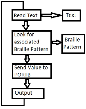
Page|19 To actuate the Braille pattern first the text has to be read from the SD card and then each character has to be cross-referenced with its equivalent Braille pattern from a table. The resulting pattern is then sent to the output and the process repeated over again for the next characters. The following Figure 20 shows the flow diagram of the code.
Figure 20 Flow Code Diagram
The code to achieve the task was broken down in two steps. The first step being able to read text from within the code and convert to Braille and the next step being able to read the text from an external SD card. To be able to convert the text to Braille a table with the Braille pattern for the entire alphabet, numbers (0-9) and symbols was created in a form which could be sent to the output. To do this each Braille pattern was turned into binary code with ‘1’ being dot on and ‘0’ being dot off. Eight dot Braille was chosen because of its ability to encode all the character information in a single cell. The following Table 8 shows an example of a few characters. The Figure 21 shows how the Braille cell is configured and the encoding of the character detail.
Table 8 Braille Code to Binary Format
The Braille code in binary format can then be sent to the output pins on the Arduino which set the required pins high and low. The following pages explain the development of the Arduino code for the EBDR.
B 11010000
G 11001100
5 10000101
3.1.1 Braille Translation
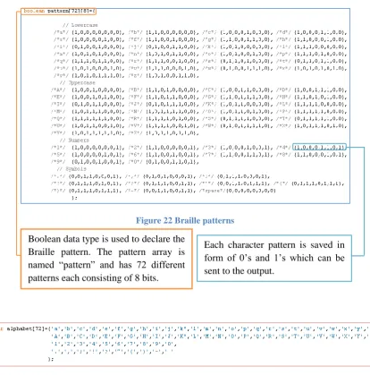
[image:29.595.90.505.103.523.2]The following Figure 22 shows the Braille pattern encoded in binary form in the Arduino code.
Figure 22 Braille patterns
Figure 23 List of characters
A list of all 72 characters was declared as char as shown in the above Figure 23. The char identifier is followed by the name “alphabet” which is used to call the list later in the code.
Boolean data type is used to declare the Braille pattern. The pattern array is named “pattern” and has 72 different patterns each consisting of 8 bits.
Page|21
Figure 25 Setup outputs
The setup as shown in Figure 25 is kept simple with only the outputs used declared. In order to set a pin to output mode a function from the Arduino’s library can be used. The pin Mode function has two parameters which can be set, the pin and its mode; input/output. In the code the pin Mode function was called and the parameters set to output but the pin number was set as a variable p. The function was called within a for loop which was set to increment p from 2 till 9. This made the function keep looping until pins 2 till 9 were set to output.
Figure 26 Main loop
The actual work happens in the main loop which is initiated with a void loop() and can be seen in Figure 26. Firstly a for loop is used to select a dot, within that loop a while loop is used to find the pattern for the text. The line while(alphabet[x] != input.charAt(letter)) { x++; } says if alphabet is not equal to input then increment x which changes the position in alphabet list. The while loop continues until the statement is true at which point the program continues to the next statement. The statement digitalWrite(dot, pattern[x][dot-2]); uses the write function from the Arduino library. The function is followed by its parameters which in the case of digitalWrite is pin number and value to be sent to it. In the statement used the parameters are defined as the value of dot for the pin and the state in the pattern array at the position x, the [dot-2] adjusts the position of x to account the pins starting at 2 and not0. The for loop ends with the brace after that statement.
The for loop is followed by an if else statement if(letter==input.length()-1) { letter=0;} else{letter++;} which says if the value of letter is equal to length of input string then reset letter to 0 otherwise increment the value of letter. The value of letter used in the while loop to determine the position in input.
3.1.2 SD Interface
The SD card interfacing for the EBDR requires an extra SD shield to be attached to the Arduino Mega2560. The adafruif SD breakout board was chosen for this because of its simplicity in design. It provides a way to interface a microSD card with the Arduino without the unnecessary extras. The following Figure 27 shows the microSD shield which was used with the pinout connection to the Arduino Mega2560.
Figure 27 Adafruit microSD shield [32]
The adafruit shield requires its own library which is available from the adafruit website [32]. Once downloaded and linked to the Arduino software it can be called up when required by using #include <SD.h> as was done in the code.
Figure 28 SD Declarations
For the SD card to work a few things first need to be declared as shown in Figure 28. For SD card shields a chip select pin has to be declared which varies depending on the board used. For adafruit interfacing with mega2560 the pin connects to pin 53 on the Arduino so has to be declares by const int intChipSelectpin = 53; statement.
Before the start of the code a few global variables first needed to be declared. A variable myfile is declared as a file for when a file is read from the SD its name can be stored using the variable. The name of the file from the SD card “test.txt” is saved as a constant string called strFileName. Another string strLineRead is
5V 53
51
50
Page|23
Figure 29 SD Setup
The setup as shown in Figure 29 required some extra code for the SD card reading to work. Firstly the serial reporting was setup to assist with debugging if required later. It was achieved by the command Serial.begin(9600); which initiated serial communication at 9600 bits per second; a standard for Arduino serial communication. It was then followed by Serial.print(“Just began…”); which prints “just began…” on the serial monitor when the program starts.
A variable Success was declared as a Boolean function to help confirm successful initialization of the SD card. The variable success is used to store the value of the initializeSDCard function which is setup later in the code.
An if statement was used to determine the progression of the program by saying if the previously declared Boolean success is true then call the ReadFileFromSDCard function. If it is not then the next if statement prints "Card Reading stopped with errors!" to the serial monitor.
The original input string is also updated with the strLineRead. This allows for the code in the main loop to remain unchanged. Two of the functions called in the setup loop are declared at the end of the code.
Figure 30 Initialize SD Card Function
For the SD library to work the SS pin on the board has to be declared as an output. The SS pin on the Arduino Mega2560 is pin 53, which is already declared in the SD library. All that is required is to set it to output which was done using the statement pinMode(SS, OUTPUT);.
The main part of InitializeSDCard function is to check whether the microSD card is inserted or not. An if statement was used to say if the command SD.begin does not detect SD card through intChipSelectpin which is pin53 then print “Initialization failed!” to serial monitor and return false.
[image:33.595.89.505.226.496.2]If it does not detect that then the code moves on to the following if statement which prints “Initialization done.” to serial monitor if serial reporting has been turned on. The code then moves to return true to report success.
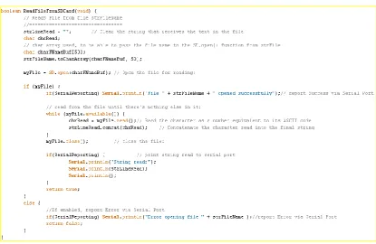
Figure 31 Read File from SD Card Function
The read file from SD card function shown in Figure 31 actually reads the data from the SD card. This function is also declared using Boolean as true or false states are required when called upon in the setup loop. Firstly the strFileRead is cleared ready to receive the text in the file. A few variables were also declared like the charFNameBuf[50] which is used as a buffer while passing the file. The file was opened with the command SD.open(charFNameBuf) and stored in the variable myFile.
Page|25
3.2 Hardware Design
The EBDR requires text in Braille format to be actuated on a finger. The Braille pattern received from the Arduino is in the form of eight pins at a state high or low, each pin representing a dot. Each actuator was connected to the outputs of the Arduino.
3.2.1 Actuators
Many of the actuators reviewed earlier are suitable to actuate the Braille dots. Unfortunately most of the actuators ideal for the device are still currently in development and require refinements until they are available. Other actuators are too large to be arranged in a Braille formation or are too expensive to get hold of to experiment.
To test the feasibility of the EBDR a Braille module is required which can actuate the pattern to be felt by a finger. For this test the overall compact form factor of the Braille module isn’t required except that the Braille dots fit within the standard cell dimensions.
As the Nitinol wire is inexpensive and is readily available, it was chosen to build the actuator. The Nitinol wire is available in different sizes of length and thickness. The differences in thickness affect the speed and strength of the actuation. The thicker the wire the more force it can exert but at a slower rate. However, the thinner the wire the faster the actuation, but with a loss of force. Nitinol wire with a diameter of 0.5mm was chosen to design the actuator due to its fast switching ability.
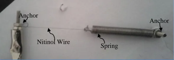
[image:34.595.150.445.476.578.2]To build the actuator the wire was cut to length. One end was attached to cardboard and on the other end a spring was attached to apply a reverse force to pull the wire back to its original length when cooled. Due to the Nitinol being an alloy of nickel and titanium solder does not stick to it, therefore crimps are usually used to make an electrical connection and fasten it to a structure. In this case the ends were held by squeezing them in between a M2 nut and bolt. An electrical connection was made by attaching crocodile clips to the ends of the bolts. Although crimps are more secure they are hard to source for the size needed and they don’t allow for adjustments in length once crimped as nuts and bolts do.
Figure 32 Nitinol in Series Configuration
In a simple series configuration with the Nitinol wire attached to a spring on one end as shown in Figure 32, the Nitinol moves only very slightly, barely noticeable. In order to amplify the actuation a few more complex configurations were experimented with. One of those used a lever to amplify the movement of the Nitinol. The lever configuration has the wire attached to one end of the lever close to the fulcrum and a spring on the other end to provide the opposing force. When the Nitinol is activated, it pulls the lever down; the small movement on one side of the fulcrum is amplified by the lever on the other side. The amplification depends on the length of the lever and where the Nitinol is attached to it. Figure 33 shows the lever configuration.
Nitinol Wire
Spring Anchor
Figure 33 Lever Configuration
The lever configuration does amplify the movement of the Nitinol considerably but due to the pulling forces on the Nitinol it breaks easily and often. The complexity of having many parts also makes it difficult to control the amount of movement, and replicating seven more with similar amounts of movement is impossible with so many variables.
[image:35.595.123.475.416.530.2]Another configuration experimented with was the V configuration where the Nitinol is anchored at both ends with bolts and a spring pulls the wire from the middle forming a V with the Nitinol. When the Nitinol is activated it shrinks and the point of the V moves up, when it cools the spring pulls the point back to the original position. The following picture in Figure 34 shows the V configuration:
Figure 34 V Configuration
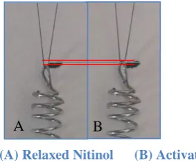
The V configuration shown in Figure 35 amplifies the movement slightly, enough to be seen. The figure below shows the Nitinol in a relaxed state next to an activated one to compare the amount of movement.
Nitinol Wire
Spring
Anchor Anchor
Fulcrum
Lever
Nitinol Wire Spring
Anchor Anchor
[image:35.595.229.371.597.713.2]Page|27 of the V. This was done by increasing the distance between the two ends of the Nitinol wire. Best performance was achieved when the V was opened up in to a horizontal line with the spring pulling down from the middle. The following Figure 36 shows the wide angle V (WAV) configuration actuator.
Figure 36 Wide Angle Configuration
The WAV configuration amplified the actuation to the amount required for the Braille actuator. The Figure 37 below shows the comparison of the relaxed and activated Nitinol.
The WAV configuration as shown in Figure 36 was chosen to build the actuators to raise the Braille dots. In that configuration the Nitinol pulls the spring up and when relaxed the spring pulls the Nitinol back down, but for the EBDR a pin needs to be pushed up a few millimetres through a hole on a flat surface. It also needs to actuate eight pins arranged in two columns of four dots so each actuator needs to occupy limited space. The actuator was modified to incorporate a pin and minimize its size.
The Braille pins were made using parts which were available at hand. Figure 38 shows the parts used to build the Braille pin alongside a fully constructed pin. The springs were taken out from pens as well as the ink tubes. The thin rods were taken out of lever arch folders and screws and washers were bought from a local hardware store. The M1 screw was longer than required so was sawed in half and then screwed in to the bottom of the plastic ink tube which had a slightly smaller diameter hole, thus providing a tight fit. The plastic ink tube was cut to 1.5cm and the rod was pushed in through the other end, the rod had the same diameter as the inner diameter of the ink tube so was a snug fit.
Figure 38 Braille Pin Construction Figure 37 Amount of actuation in WAV configuration
Nitinol
Spring Ancho
r
Ancho r
[image:36.595.154.443.331.393.2]To reduce the size of the actuator the spring was moved up inside the opened up V. This way the spring pushes the wire instead of pulling, as the springs in pens are compression springs it works better this way. The pin is then slid inside the spring and the slot in the screw rests on the Nitinol as can be seen in Figure 39. Two bolts at the top in line with the ends of the Nitinol hold the spring in place. When the Nitinol is activated it shrinks and pushes the pin up and compresses the spring which in turn pushes the Nitinol back in shape when it cools. Figure 40 shows the actuator fully assembled:
Figure 39 Nitinol resting in screw slot Figure 40 Fully assembled actuator
The actuator works consistently and provides the required amount of actuation. Figure 41 shows the comparison of the relaxed and activated actuator side by side. The Nitinol wire reacts fast when the required power is applied to it and can actuate in less than 0.5 seconds. To reset the actuator, the power is switched off at which point the wire starts to cool and the spring pushes it back to shape. The cooling period is considerably longer and can be in excess of 1 second. To reduce the reset time a stronger opposing force can be applied but that then requires more power to actuate and overcome the force. It also increases the likelihood of the Nitinol wire breaking due to excess stress. Another way is to help the wire dissipate the heat quicker. A simple way to do this is to use a fan to create airflow around the Nitinol wire. A small fan scavenged from a computer was used to cool the Nitinol which reduced the reset time to less than a second.
Figure 41 Actuator relaxed vs activated
[image:37.595.140.456.413.474.2]Page|29 The prototype with all actuators arranged in a Braille cell was constructed with plates of Plexiglas as the base. In the chosen design the actuator spans horizontally so the four pins in the Braille cells can easily be stacked on top of each other. But the two columns are forced apart due to the size of the actuator which spans about 9cm from one end of the Nitinol to the other. To overcome this the actuators were divided into two columns and each column built on a different level, with the pins of the bottom column being longer so they extend through to the same height as the tip of the top level as can be seen in Figure 44. The actuators on the top level were offset at 45 degrees so that the pins coming through from the bottom level don’t make contact with the Nitinol wire. Figure 42 and Figure 43 show the arrangement used for the eight actuators to form a Braille cell. The top plate sits on top of the bottom plate with a 4cm gap in between for the actuators. The holes (red on the diagram) on the top plate for the left column actuator help line up both plates. Further details on the dimensions can be found in the appendix section C.
Figure 42 Top actuator plate Figure 43 Bottom actuator plate
Holes were drilled in the Plexiglas plates in the configuration shown in the above Figure 42 and Figure 43. Large holes with a diameter of 3.6mm were drilled half way through the plate for the springs to slot in and a smaller 1.5mm hole inside it going all the way through for the pins. Both plates had a column of these holes for each column of the Braille cell. The top plate had another column of the 1.5mm holes for the bottom actuators to come through to form the entire Braille cell. Holes with a diameter of 1mm were drilled for the Nitinol wire which was secured in the hole using screws.
An electrical connection with the Nitinol was made by attaching a wire to the screw holding the Nitinol in place. One side of the actuators was connected together and grounded. Power was applied to the other side to activate each actuator. Figure 44 shows the actuators on the top and bottom plate.
Spring Nitinol
Braille Pin Anchor for
Nitinol Holes for bottom
[image:38.595.60.538.242.380.2]plate actuators
[image:38.595.79.516.551.738.2]3.2.2 Drive Electronics
[image:39.595.154.429.171.314.2]The Nitinol requires considerable amount of current to actuate the required amount. Approximately 500mA is required to actuate each actuator at the required speed. To prevent the pins on the Arduino from being damaged transistors were used to power the actuators. The transistors were used as a switch to direct power from the battery to the Nitinol wire. NPN Darlington pair transistors TIP122 were used as they are able to handle the large current flow and are intended for switching applications.
Figure 45 Transistor Connections
Page|31 Figure 46 shows the drive circuit integrated with the connection module linking everything together. Push to make switches were used to manually turn on the actuator and LED’s were also connected in parallel with the Nitinol actuators to indicate on/off states when the Braille cell is not visible.
Figure 46 Drive Circuit with Indication LED's
[image:40.595.88.519.457.666.2]The different parts were assembled together on the Plexiglas. Wires with pins and connectors were used to interface the Arduino with the actuators as they could be easily connected and disconnected. Holes were drilled in the top plate to mount the eight manual override Push to make switches and indication LED’s in Braille configuration. A fan was mounted on the side of the plates so that it would blow air over all eight actuators. The image in Figure 47 below shows the top view of the fully assembled EBDR.
Figure 47 Electronic Braille Document Reader Prototype
Indication LED’s
TIP122
Input from Arduino Push to make
Switches
Fan
Fan Fan Switch
Override switched
LED’ s
4.0 System Test
The EBDR consists of two main parts, the text processing module which is part of the software section reads text from SD card and translates into Braille pattern, and the actuator module part of the hardware section which actuates the Braille pattern. It was designed and built in two modules so it could be tested separately and as a single integrated system. The following sections describe the test procedure for the separate modules and the EBDR as a complete product.
4.1 Text Processing
[image:41.595.100.500.272.436.2]To test the code and determine if the Arduino was able to translate the text into Braille pattern, an LED module was built. The LED’s were arranged in a Braille cell and each LED connected to a pin on the Arduino instead of the actuators. The LED’s displayed the corresponding Braille pattern, which would otherwise be actuated by the actuators. Figure 48 shows the LED module.
Figure 48 LED Braille module
A test file in .txt format was saved in the SD card with the text “PEACE be upon you! 321” to test if the Arduino would translate the text correctly. The microSD card was then inserted in to the microSD card adapter on the SD shield.
The test text was also manually translated into Braille form to be able to compare the results from the LED Braille display. Figure 49 shows the text “PEACE be upon you! 321” translated in to Braille.
Figure 49 PEACE be upon you! 321 in Braille
Arduino Pins 2-9
[image:41.595.56.542.553.590.2]Page|33
4.2 Actuators
The actuators when built on the Plexiglas plates were built with push to make switches in series with them to manually turn each one of them on. LED’s were also connected in parallel to the actuators to indicate if the actuator was on or not when the pins were covered with a finger.
To test the actuators, power was applied to the circuit and each actuator was turned on one by one. The cooling fan was also turned on to help the actuator reset quicker.
4.3 EBDR
[image:42.595.136.460.252.522.2]The individual pieces of EBDR were tested independently to confirm the correct working order of each module. After the correct working order of the modules the Arduino was then connected directly to the actuator module. Figure 50 shows the fully assembled Electronic Braille Document Reader.
Figure 50 Fully Assembled EBDR
The same text file was used to test the whole assembly as the one used to test the Arduino module individually. Power was supplied to the actuator module and the fan turned on then the Arduino was also turned on to provide the Braille pattern to the actuators.
5.0 Results
The individual modules of the EBDR, and the fully assembled EBDR prototype were tested using multiple inputs and the output results were recorded for further comparison and analysis. The following sections present the results of the tests conducted on the individual modules as well as the assembled prototype.
5.1 Text Processing
[image:43.595.195.406.219.348.2]The serial monitor showed the progress of the code. It indicated the SD card initialized correctly and displayed the text from the test.txt file on the serial monitor. Figure 51 shows the output on the serial monitor.
Figure 51 Serial Monitor output – Successful initialization
Straight after the report on the serial monitor the LED started displaying the Braille patterns. Pictures of each pattern was taken and compared with the expected output. The Braille patterns matched perfectly. The following image in Figure 52 shows all the Braille patterns displayed in sequence.
P E A C E b e u p o n
y o u ! 3 2 1
Figure 52 Braille Output on LED Braille cell
[image:43.595.99.498.423.572.2]Page|35
5.2 Actuators
Each actuator was actuated manually using the push to make switches. The actuators actuated as required. The indicator LED’s also displayed the actuated dot. They were then actuated in different Braille configurations. Figure 54 below shows the actuators and the LED’s displaying the Braille patterns.
d k o
Figure 54 Actuator Test
The actuators when actuated individually functioned well, but when actuated in group had problems. When actuating two dot combinations the actuators didn’t have much problem but additional dots added a delay between them. The dots actuated one after another instead of all together. This was because the actuators required extra power at the start than was available to all at once.
The actuators also varied slightly in the amount of actuation so the heights of all the dots were slightly different.
5.3 EBDR
At first the Braille patterns seemed to be actuating randomly. With detailed inspection of the system it was discovered that the Arduino was scrolling through the patterns too fast for all the actuators to finish actuating. To rectify the problem the scroll speed was slowed down by setting the delay in the Arduino code to 3 seconds. This gave ample time for all the actuators to finishing actuating and the user to read the pattern. Figure 55 below shows the actuators actuating the text from the SD card in Braille pattern.
P E A C E b e
u p o n y o u !
3 2 1
Figure 55 Actuated Braille Text.
The volunteers chosen to test the EBDR read the text by touch alone. They were not able to read at first but after a few minutes getting themselves used to it they were able to decipher the text but at a very slow rate. After about 15 to 20 minutes of practice the speed increased though still a long way from their usual reading speeds.
[image:45.595.129.470.168.504.2]Page|37
6.0 Discussion
The aim of the project to prove the feasibility of a device which would read text from an external memory and actuate it in Braille form to function as an e-book reader for the blind was successfully met. The EBDR proved the feasibility of such a device. The following sections discuss the design, testing and results of the project.
6.1 Text Processing
The decision to choose Arduino for the text processing proved to be the right decision as it made the programming a lot simpler. The Arduino development environment has a vast library of functions and large open source
![Figure 4 Quote in Grade 2 Braille [8]](https://thumb-us.123doks.com/thumbv2/123dok_us/334629.1034484/17.595.56.540.170.269/figure-quote-in-grade-braille.webp)
![Figure 8 Diagram explaining the Internals and Functions of a Squiggle Motor [ 21]](https://thumb-us.123doks.com/thumbv2/123dok_us/334629.1034484/21.595.93.495.255.574/figure-diagram-explaining-internals-functions-squiggle-motor.webp)
![Figure 13 Right Angle Pull/ Simple Lever Examples [27]](https://thumb-us.123doks.com/thumbv2/123dok_us/334629.1034484/24.595.62.534.421.628/figure-right-angle-pull-simple-lever-examples.webp)
![Figure 17 Braille Display using Bucky-gel [29]](https://thumb-us.123doks.com/thumbv2/123dok_us/334629.1034484/26.595.208.394.212.396/figure-braille-display-using-bucky-gel.webp)