2018 International Conference on Modeling, Simulation and Optimization (MSO 2018) ISBN: 978-1-60595-542-1
Modeling and Analysis of the Support System of Space-based
Anti-missile Information Based on UML
Chen-sen XIA
1, Hui YAN
2, Yue WANG
1and Ling SHI
11Space Engineering University, Graduate College of Space Engineering University,
Ba Yi Road 1# Beijing, 100140, China
2Space Engineering University, Space information College of Space Engineering University,
Ba Yi Road 1# Beijing, 100140, China
Keywords: Space-based information support system, Anti-missile system, UML, Modeling.
Abstract. The purpose of this paper is to achieve the conceptual model and analysis on the support system of space-based anti-missile information. In this paper, Unified Modeling Language (UML) is used to conduct the model and analysis of the system. With respect to features such as functional requirements, data features, object relationships, dynamic behaviors and information interaction, a variety of view models were established to describe the concepts. Use case diagrams, class diagrams, sequence diagrams, communication diagrams and analysis class diagrams were drawn thanks to the IBM Software Delivery Platform. The producrs provided a conceptual analysis about the space-based information support on anti-missile system and foundation for the simulation of the follow-up system. It indicates the complexity of the system and the necessity of modeling and analisis through this paper.
Introduction
The support system of anti-missile information is a general term for the group offering information on decisions for Anti-Ballistic Control Center [1]. With the development of space technology and near space technology, early warning satellites, space target detectors and near space probes have all become important components of the support system of anti-missile information, and play an increasingly important role. This paper starts with the study of the support system of space-based anti-missile information in the general sense and is based on the U.S. anti-missile system. The support system of space-based anti-missile information in this paper includes many space-based parts, such as satellites, target monitors, ground-based monitoring and control stations that work with them. In addition, it also includes ground-based radar systems and communications relay systems cooperating with them [2] [3]. At present, the conceptual analysis of the overall anti-missile system process mainly adopts multi-view methods, such as multi-view analysis using the DoDAF framework and basic workflow [4] or swimlane diagram. DoDAF [5] framework supplies multi-view products in a variety of languages while flow chart or swimlane diagram analysis is relatively rough, so this paper applies UML (Unified Modeling Language) to system modeling analysis.
Requirements Modeling
A system requirement [7] model can be established through use cases based on the needs of the system. Use cases mainly describe [8] functional requirements which describe the behavior or functionality of a system in various situations when it responds to a user's request. Use case analysis products include use case diagrams and written use cases [6]. Use case analysis [9] can identify the use cases of the execution process, the various classes of events, and connect the activity of the use case to a specific class in order to find the responsibility and attributes of the class and their relationship with each other which can normally determine the duties of each use case in the system. Besides, use cases can serve as the basis for building a model that drives the needs of the entire organization [10].
In the Use cases analysis of the support system of space-based anti-missile information, as the main work can be divided into three parts: missile launch warning, missile tracking and identification, and interception, among which the first part is most significant. So this paper selects the first part for use case analysis.
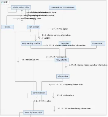
[image:2.612.113.501.361.651.2]In the “Missile Launch Warning” section, the participants are missiles and command and control center. Several use cases are detecting missile launch, relaying information, early warning information settlement, false alarm elimination and alarm issue. Figure 1 shows the use cases, participants and the relationships among the use cases. There is common association, including and expansion relations. A detailed script description of the use case model can be clearly seen in the written use cases shown in Table 1.
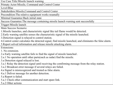
Table 1. Written use case about missile launch warning.
Use Case Title:Missile launch warning
Primaty Actor:Missile, Command and Control Center Level:Blue
Stakeholders:Missile,Command and Control Center Precondition:The relative equipment works noamally Minimal Guarantee:Back initial state
Success Guarantee:The message containing missile launch warning sent successfully Trigger:Missile launch
Main Success Scenario:
1.Missile launches, and characteristic signal like tail flame would be detected. 2.Early warning satellite senses the characteristic signal of the missile launched. 3.Detection signal is relayed to control station.
4.Control center calculates the detected signal, find missile launched, and eliminates the false alarm. 5.Report solved information and release missile attacking alarm.
Extensions: 1. No extension.
2.a Early warning satellite fails to find the signal of missile launched . 2.a.1 No operation until other parts(such as radar) find the missile. 3.a Detection signal relayed is lost.
3.a.1 Relay the detection signal until receiving the comfirming message from the relay station. 3.a.2 Broadcast error message if several relays are failed.
4.a Signal is misrecognized and treated as false alarm. 4.a.1 Deliver message for another detection.
5.a Report is failed.
Figure 1. Use case diagram on missile launch warning.
Conceptual Data Modeling
The Relational Data Model (RDM) is a detailed model that describes the overall structure of the organization’s data; and is independent of any implementation [6]. The conceptual data model is usually graphical and in this paper it is displayed as a class diagram drawn in UML. Conceptual data modeling is an important intermediate step in the analysis of class diagrams. After logical data modeling [11] is used to convert object relationships into object relational data, object relationships can be identified as entity classes. And then, by adding boundary classes and controlling classes, sequence diagrams can be drawn to achieve behavioral relationships.
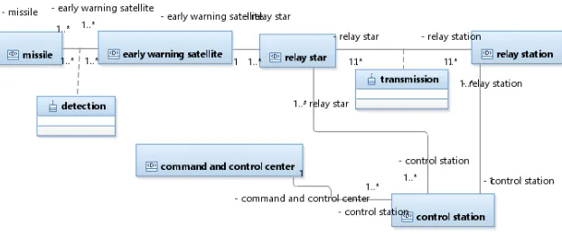
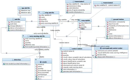
In the conceptual data modeling of the support system of space-based anti-missile information, based on the use case of "missile launch warning" in requirement modeling, the conceptual model is drawn as Figure 2, in which the attributes of each class are shown in Table 2.
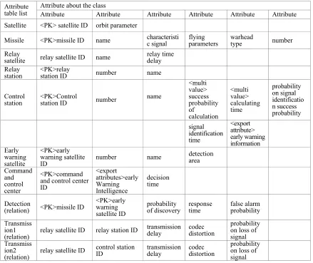
Table 2. Detailed attributes of classes.
Attribute
table list Attribute about the class Attribute Attribute Attribute Attribute Attribute Attribute Satellite <PK> satellite ID orbit parameter
Missile <PK>missile ID name characteristic signal flying parameters warhead type number
Relay
satellite relay satellite ID name relay time delay Relay
station <PK>relay station ID number name
Control
station <PK>Control station ID number name
<multi value> success probability of calculation <multi value> calculating time probability on signal identificatio n success probability signal identification time <export attribute> early warning information Early warning satellite <PK>early warning satellite
ID number name
detection area Command and control center <PK>command and control center ID <export attributes>early Warning Intelligence decision time Detection
(relation) <PK>missile ID
<PK>early warning satellite ID
probability
of discovery response time false alarm probability
Transmiss ion1
(relation) relay satellite ID relay station ID
transmission
delay codec distortion
[image:3.612.88.527.383.752.2]Figure 2. The class diagram on conceptual data model.
When creating a conceptual data model, firstly the classes in the use case should be identified. After analyzing the use cases, it’s easy to find that there are several obvious classes like missile, command and control center, early warning satellite, relay satellite, relay station, and control station. Besides, there are two more classes: detection and transmission. Next, attributes need be split up and assigned to the classes, as shown in Table 2.
In the class diagram, the number of the association between the classes indicates the cardinality of the class and the association class generally appears in the many-to-many (m: n) association [12]. In the attribute table, “PK” indicates that the attribute is an identifier of the class. It could be found that in Figure 2 each missile can be detected by multiple satellites and each satellite can recognize multiple missiles. So, this is a many-to-many (m:n) relationship. Each early warning satellite can only send information to one relay satellite, while one relay satellite can receive information from multiple early warning satellites. So, this is a one-to-many (1:n) relationship. Similarly, the degree of the relationship between other classes can be described in Figure 2.
Object-Relational Data Modeling
The Object-Relational Data Model (ORDM) is a relational data model with an object-oriented extension. The Relational Data Model (RDM) is a data represented as a set of related tables or relationships. The object-relational data model is described with the object relationship. The transformation from concept of data model [6] to the object relationship can be completed in four steps: transforming classes, transforming relationships, normalizing the object relationships, and merging the relationships between the objects.
When converting the conceptual data model of the support system of space-based anti-missile information into an object relationship, given the complexity of the space-based anti-missile information support system, it is difficult to finally merger the object relationship into a use case. However, internal merging of “Launching early warning”, “tracking identification goals”, “implementing intercepts” separately seems to reduce redundancy to some extent and provides a basis for separately creating analysis class diagrams. Transforming the conceptual data model of the “missile launch warning” use case into the object relationship is taken as an example and the specific steps are as follows:
Transforming Class
Based on the classes in the conceptual data model, the relationships are transformed into object relationships to get the initial object relationships and the results are as follows:
Missile (missile ID, name, number, characteristic signal, flying parameters, warhead type)
Early warning satellite (early warning satellite ID, name, number, detection area)
Relay station (relay station ID, name, number)
Control station (ID, name, number, <multi-value> success probability of calculation,
<multi-value>calculating time, probability on signal identification success, signal identification time, <export attribute> early warning information)
Command and Control Center (command and control center ID, <export attributes> early warning
intelligence, decision time)
Transforming Relationship
When transforming relationships, it is important to pay attention to the degree of relationship and the multiplicity of relationships. In multiplicity numbers, the largest cardinality usually determines the structure of the relationship of result objects.
A binary one-to-many (1: n) relationship shows in this way that the primary key attribute of the "one" part entity in the relationship is added as a foreign key in the relationship "multi" part relationship. If it is one to one (1: 1) relationship, the primary key attribute from any class could be added to the other as a foreign key. The relationship between early warning satellites and relay satellites, relay stations and control stations, control stations and command and control centers are in line with this conversion. After the transformation, some relationships changed are listed here:
Relay satellite (relay satellite ID, name, number, relay time delay, early warning satellite ID)
Control station (control station ID, name,number,<multi-value> success probability of calculation,
<multi-value>calculating time, probability on signal identification success, signal identification time, <export attribute> early warning information, command and control center ID)
Binary many-to-many (m: n) relationships (or relational classes) need to be created as a single object relationship. The primary key of this relationship is a combined key consisting of the respective primary key of each entity in the relationship, and any non-key attributes associated with the relationship are included in the created object relationship. The relationships between missiles and early warning satellites, relay satellites and relay stations, relay satellites and control stations are in line with the conversion. The results of further conversions are as follows (only changes or additions to object relationships are listed):
Detection (missile ID, early warning satellite ID, probability of discovery, response time, false
alarm probability).
Transmission1 (relay satellite ID, relay station ID, transmission delay, codec distortion(involved
signal quality), probability on loss of signal).
Transmission2 (relay satellite ID, control station ID, transmission delay, codec distortion
(involved signal quality), probability on loss of signal).
Normalizing the Relationship between Objects
Normalizing object relationships requires that these relationships satisfy the third paradigm but not the first paradigm. After inspection, the above results are in line with the third paradigm.
Merging Object Relationships
The merger of the object relationships mainly focuses on the three problems that may appear in the integration: synonyms, homonymys and dependencies between non-key attributes. The final object relationship after the merger is as follows:
Early warning satellite (early warning satellite ID, name, number, detection area)
Relay satellite (relay satellite ID, name, number, relay time delay, early warning satellite ID)
Control station (station ID, name, number, <multi-value> success probability of calculation,
<multi-value>calculating time, probability on signal identification success, signal identification time, <export attribute> early warning information, command and control center ID)
Command and Control Center (command and control center ID, <export attributes> early warning
intelligence, decision time)
Missile (missile ID, name, number, characteristic signal, flying parameters, warhead type)
Relay station (relay station ID, name, number)
Transmission1 (relay satellite ID, relay station ID, transmission delay, codec distortion (involved
in signal quality), probability on loss of signal)
Transmission2 (relay satellite ID, control station ID, transmission delay, codec distortion
(involved in signal quality), probability on loss of signal)
Behavioral Modeling
Behavioral modeling refers to the process of modeling the information interacting in a system and mainly to make clear the message delivery and responsibility distribution [13]. Behavioral modeling mainly refers to help establish the analysis class diagram [14] through the preparation of sequence diagrams and communication diagrams. The way to conduct behavioral modeling is as follows. Firstly construct the analytic classes relying on the object relationships and get the entity classes, control classes, and boundary classes. Secondly, the sequence diagram should be drawn and transformed into a communication diagram on the basis above. Thirdly, the analysis class diagram can be drawn with the help of the communication diagram.
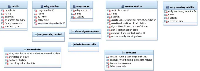
[image:6.612.138.478.401.523.2]The details of drawing the analysis class diagram about support system of space-based anti-missile information are as follows. Similarly, it’s supposed to select a typical use case “missile launch warning” in the process of drawing analysis class diagram. Based on the object relationships, the object relation should be transformed into the entity class, while the boundary class and the control class could be obtained by the method of typologically analysis. Some analysis classes are shown in Figure 3. Furthermore, the missile feature table is introduced between the participant missile and the use case, and the alarm signature table is introduced between the participant control center and the use case. Besides the control class of early warning control should be contained into the use case. Others can be created as entity classes based on the object relationship.
Figure 3. The class diagram from configuration about missile launch alarm.
Figure 4. The sequence diagram about missile launch alarm.
[image:7.612.125.489.333.727.2]On this basis, analysis class diagram shown in Figure 6 can be drawn easily.
Figure 6.The analysis of class diagrams about missile launch alarm.
In the analysis class diagrams, behavior information is not marked on the above, because the analysis class diagrams drawn with the UML method don’t explicitly support the data modeling. Due to this case, it has a priority to conduct the structural relationship modeling in the analysis class diagrams instead of showing both data relationship and structural relationship in the diagrams above. When the behavioral relationships need searched, it is easy to get the information from the sequence diagram or the communication diagram. If both the two kinds of relationships on the analysis class diagrams appear, it would confuse the view model and make it hard to understand the system from the view model.
Summary
Object-oriented approach and UML Unified Modeling Language are used to research the support system of space-based anti-missile information in this paper. The requirements modeling, conceptual data modeling, object relation modeling and behavioral relation modeling are carried out to obtain the models of sequence diagrams, communication diagrams and analysis class diagrams, and the products are drawn on IBM RSA (IBM Rational Architect Software) development platform. It is of some reference to cognize and analyze the system from the aspects of the data characteristics and behavioral relationship. At the same time, it ensures the rationality of system abstraction in the follow-up research to a certain degree and plays a fundamental role in the execution and analysis of system information support models.
References
[1] Hao Xu. Qing-hua Xin, Military conceptual modeling of the formation process of the final anti-missile space information. J. Information exchange. 2016(10)
[3] Hui Luo. Jie-sheng Chen. Xing-yun Wang. Research on the development status and integration trend of US military anti-missile and anti-satellite system. J. Attack and defense system. 2015(10). [4] Liang Xu. Li Zhang. Zhi-qiang Fan. An Approach of Real-Time Workflow Modeling Based on UML. J. Journal of Computer Research and Development. 2010(07)
[5] Yi Liu. Zhi-yi Ma, Xiao He, Wei-zhong Shao. Approach to Transforming UML Model to Reliability Analysis Model. J. Journal of Software. 2010(02)
[6] Joey George. Dinesh Battra. Object-oriented systems analysis anddesign.2ed.Beijing, Tsinghua University Press, 2016.
[7] Grady Booch. James Rumbaugh. Ivar Jacobson. Unified Modeling Language User Guide2ed. Beijing: The People’s Posts and Telecommunications Press, 2017.
[8] Guoming Yuan. Rui Liu. Bo Fan. Use Case Diagram of UML Steps Design Research in Software Engineering. J. Microcomputer Application. 2014(30).
[9] Ju Huang. Research on library information management system based on UML modeling. J. Wireless Internet Technology. 2013(02).
[10] Er-pin Zhao, Liang Wang. Research on the modeling process of UML. J. Tibet's Science & Technology. 2011(12).
[11] Yong Peng. Zhi-cheng Liu. Jun Zhang. Dongshen Lin. UML Modeling Example Tutorial. Beijing: Publishing House of Electronics Industry, 2016.
[12] Ke-hua Gao. Na Li. UML Software Modeling Technology—Based on IBM RSA Tools. Beijing: Tsinghua University Press, 2017.
[13] Yong Li. Xiao-jun Yang. UML2 Introduction and Improvement of Software Modeling. Beijing: Tsinghua University Press, 2015.