2016 International Conference on Computer, Mechatronics and Electronic Engineering (CMEE 2016) ISBN: 978-1-60595-406-6
A New Approach for Reconstructed B-spline Surface
Approximating to Scattered Data Points
Xian-guo CHENG
Ningbo University of Technology, Ningbo, 315211
Keywords: Triangle mesh, B-spline surface reconstruction, Artificial tooth, Parameterization, Scattered data points.
Abstract. An algorithm for constructing B-spline surface approximating to scatted data points of artificial tooth is presented. Firstly, the scattered data points from the laser scanning equipment are regarded as input and the triangle mesh of artificial tooth are created by the circum-sphere criterion. Secondly, the vertices of the triangle mesh are mapped into a unit square of planar parameter domain by the mean value coordinate mapping. The triangle mesh parameterization can be solving a sparse linear system. Finally, the rule sampled points of the planar parameter domain are mapped into the triangle mesh in 3D space by the inverse mapping method. The rule sampled points on the triangle mesh in 3D space are accomplished and B-spline surface interpolating to them is constructed. Experiments show that our approach is effective to construct B-spline surface approximating to scattered data points of artificial tooth.
Introduction
Computer aided design (CAD) and Computer aided manufacture (CAM) have applied to the design and manufacture for dental prosthesis since the 1980s, the technology is called denture CAD/CAM [1-4].As we know, this can significantly shorten the period of dental prosthesis and ease the pain of dental patients. Meanwhile, it has a profound impact on the theory and practice of dental prosthesis [5, 6]. For the denture CAD/CAM, the focus is on how to construct B-spline surface based on scanned data points of artificial tooth.
B-spline surface has various useful properties [7-9] for the design of complicated geometry, making it a de-facto industrial standard among surface representation schemes in computer aided geometric design (CAGD) [8].In the reverse engineering, the data points from scanning equipment could be classified into three types according to their structure: rectangular arranged points, serial contours, and scattered points. In this paper, we propose a new approach for constructing B-spline surface approximating to scattered points of artificial tooth. Firstly, we use the circum-sphere criterion to create fast the triangle mesh of the scattered points. Secondly, we use the mean value coordinate to make that the vertices of triangle mesh in 3D space are mapped into a unit square in planar parameter domain. Points are rule sampled on the planar domain and are mapped into the triangle mesh in 3D space by the inverse mapping method. The rectangular arranged sampled points on the triangle mesh in 3D space are obtained. Finally, B-spline surface approximate to the scatted data points are reconstructed and the CAD model of the artificial tooth is provided for the prosthetic operation.
Triangle Mesh Reconstruction
Given a sequence of distinct data points P(p p1, 2, pN) in 3-D space, we propose a circum-sphere criterion to create the triangle mesh of denture. Firstly, we can select arbitrarily a point A from the data points P and find a point B in the neighborhood of A to make the distance AB minimal. AB is regarded as an edge of a triangle and a point C is selected in the neighborhood of Aor B to make the minimal interior angle of the triangle ABC to be maximal. The triangle ABC and its three edges are viewed as a seed triangle and current edges, respectively. For each edge, we can utilize the circum-sphere criterion to find a point to construct a new triangle, add it to the triangle mesh and update current boundary. Repeating this step until all the data points P are involved in the triangle mesh reconstruction. The triangle mesh growth can be explained as follows:
Step 1. Select a point A from P, find another point B in the neighborhood of A to make the distance ABminimal, AB is regarded as an edge of a triangle, look for a point C in the neighborhood A or B to make the minimal interior angle of the triangle ABC to be maximal. The triangle ABC and its edges are viewed as a seed triangle and current boundaries, respectively.
Step 2. For each of the current boundaries, look for a new point D in the neighborhood of its two ends points and create a new triangle by the circum-sphere criterion. The new triangle should satisfy the following three conditions:
① Three vertices of the triangle are not on a line.
② The shape of the triangle should be regular triangle as far as possible.
③ There is not any other point inside the triangle.
For each of the current boundaries, if we could find a point to create a triangle and tag the edge is shared by two triangles, if not, we tag the edge is a boundary of the triangle mesh.
Step 3. Update the current boundary, namely the non-shared edge of the triangle obtained in Step 2 is used as the current boundary. Repeat the step 2 until all the data points P are involved in creating the triangle mesh.
Figure 1 shows that the triangle mesh of molar is created by our approach. The scattered data points are displayed in Fig.1a and the triangle mesh created is shown in Figure 1b.
(a) scattered data points (b) triangle mesh
Figure 1. The reconstruction of the triangle mesh of molar.
Mesh Parameterization
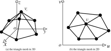
The planar parameterization of the triangle mesh is to find the mapping function, which can make each vertices of the triangle mesh one-to-one mapping each vertices of the triangle mesh on the planar parameter domain, as shown in Figure 2. Meanwhile, a reasonable mesh parameterization should make the difference between the triangle mesh in the 3-D space and the triangle mesh in the planar parameter domain is the smallest[10-12].
i V
x
z
o
y
j
U
u
v
o
[image:2.595.200.395.682.772.2](a) the triangle mesh in 3D (b) the triangle mesh in 2D
As the triangle mesh is single boundary, we exploit the mean value coordinate mapping to parameterize the triangle mesh[13]. Supposed the vertices of the triangle mesh are
3 1
{ ,..., n b| i }
V V V VIR , and the internal vertices are marked as: VI { ,...,V1 Vn}, the boundary vertices
are : VB{Vn1,...,Vn b }. The corresponding mapped vertices in the planar parameter domain of the vertices V are: 2
1
{ ,..., n b| i }
U U U U IR . The triangle mesh parameterization is included the boundary vertices parameterization and the internal vertices parameterization.
The Boundary Vertices Parameterization
In order to accomplish that the boundary vertices are mapped into a unit square in the planar parameter domain, we should select reasonably four vertices from the boundary vertices. Supposed
the distance of two adjacent boundary vertices is:
1 1 1 B V i i i
L V V
, the first vertice Va can be selectedarbitrarily from the boundary vertices VB. The second vertice Vb from VB should be selected along the
counter clockwise of the triangle mesh boundary and satisfy the following equation:
1 1 min( ) 4 b i i i a L V V
By analogy, we can find the third vertice Vc and fourth vertice Vd that should meet 1 1 min( ) 4 c i i i b L V V
and1 1 min( ) 4 d i i i c L V V
, respectively. The rest of the boundary vertices aremapped into the corresponding the edges of the unit square, as shown in Figure 3.
b V c V d V
( )Va
( )Vb
( )Vc
(Vd)
a V
Figure 3. The boundary vertices parameterization.
The Internal Vertices Parameterization
For each of the internal vertices VI of the triangle mesh, its one-ring neighborhood is Ni and its
weight factors are ij. We consider that the vertices Ui are the weighted average of the one-ring
neighborhood of VI in the planar parameter domain, that is:
i
i ij j
j N
U U
We can decompose the vertices Ui in the type (1) into the boundary vertices and the internal
vertices, namely:
i i
i ij j ij j
j N j n j N j n
U U U
, ,
As we know, the boundary vertices have been obtained in the 2.1 section, and the type (2) can be written as follows:
Ax b
1
0 others
ij ij i
i j a j N
x is the internal vertices in the planar parameters domain and unknown quantity, T
1 n
= (b , ,b )
b is
the column vector with:
1
N
i ij j
j n
b u
In order to ensure the mapping is one-to-one and the angle distortion of the triangle parameterization is minimal, we determine the positive weights ij:
tan ij/ 2 tan ij/ 2
ij i j V V / i
ij ij ik
k N
The angle ij and the angle ij are shown as Figure 4.
i V
j
V
ij
ij
[image:4.595.70.442.243.417.2]
Figure 4. The angle ij and the angle ij selection. Figure 5. The planar parameterization of molar.
The Eqs. (3) x can be resolved by the Gauss elimination method when the weight factors ij are
determined. The vertices in the planar parameter domain can be triangulated according to the order in space model. The planar parameterization of molar is as shown in Figure 5.
Rule Sampling
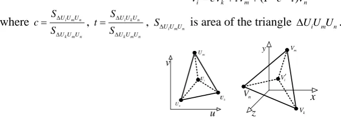
When the triangle mesh is parameterized in the planar parameter domain, we can take advantage of the inverse-mapping to sample regularly on the triangle mesh, because the vertices of the triangle mesh are one-to-one the vertices of the triangle mesh in the planar parameter domain. Supposed a point Ui from the planar parameter domain belongs to a triangle U U Uk m n, and its corresponding triangle in the 3-D space is V V Vk m n, as shown in Figure 6. The point Vi in 3-D space is as follows:
(1 )
i k m n
VcV tV c t V
where i m n k m n
U U U
U U U
S c
S
, i k n k m n
U U U
U U U
S t S ,
i m n
U U U
S is area of the triangle U U Ui m n.
u v i U k U m U n U x y z i V k V m V n V
(a) a triangle in the planar parameter domain (b) a triangle in the 3-D space
[image:4.595.57.396.616.735.2]In order to obtain (n 1) (n1) parameter points Uij ( ,u vi j) , ui i (i 0,1, , )n n
,
( 0,1, , )
j
j
v j n
n
, the unit square in planar parameter domain should be divided into n n small
squares, and n V , x denotes the largest integer not greater than x. This can make sure the
number of sampled points is approximately equal to the number of the triangle mesh vertices. The point Vi in 3-D space can be obtained by Eqs.1 and all rule sampled points in the triangle mesh should
be connected in sequence to create rectangular arranged points, as shown in Figure 7(a). For the rectangular arranged points, we can use the interpolation method[14] to construct B-spline surface interpolating to the points, as shown in Figure 7(b).
(a) rule sample points (b) B-spline surface
Figure 7. The B-spline surface of the molar
Experimental Results
The proposed approach has been tested for various scattered data points of artificial tooth. In this paper, molar, canine, incisor and dental crown in the prosthetic operation are included to demonstrate the usefulness and quality of our approach.
Firstly, for a molar model, there are 12099 vertices and 24069 triangles, respectively. The rule sample points in 3-D space is shown in Figure 7(a) and the constructed B-spline surface is shown in Figure 7(b). The maximal deviation between the scattered data points and the constructed B-spline surface is 0.117 mm.
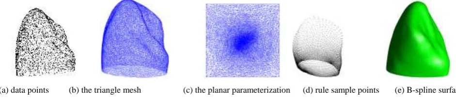
Secondly, there are 5678 vertices and 11256 triangles in a canine model, as shown in Figure 8(a) and Figure 8(b), respectively. The maximal deviation is 0.046 mm, and the reconstructed B-spline surface is shown in Figure 8(e).
[image:5.595.59.530.506.607.2]
(a) data points (b) the triangle mesh (c) the planar parameterization (d) rule sample points (e) B-spline surface Figure 8. The B-spline surface reconstruction of canine.
Thirdly, there are 3986 vertices and 7908 triangles in an incisor model, as shown in Figure 9(a) and Figure 9(b), respectively. The maximal deviation is 1.835 mm, and the reconstructed B-spline surface is shown in Figure 9(e).
[image:5.595.71.526.672.775.2]
Conclusions
This paper presents a new approach for B-spline surface reconstruction based on scattered data points. Through the circum-sphere criterion, the triangle mesh can be easily acquired according to the requirement. This article presents a method of the triangle mesh parameterization that the vertices of the mesh are mapped into a unit square of planar parameter domain. The rule sampled points of the planar parameter domain are mapped into the triangle mesh in 3D space and the rectangular arranged sampled points of the triangle mesh can be obtained. B-spline surface approximating to scattered data points can be accomplished. Experimental results show that our approach is effective in reconstruction B-spline surface of the artificial tooth. The future work of the main is to improve the accuracy of surface reconstruction and adaptive sampling.
Acknowledgement
This study was supported by Ningbo Natural Science Foundation of China (2014A610090) and Educational Commission of Zhejiang Province of China (Y201431835).
References
[1] Van-Der-Zel J, Vlaar S R, Wj, Davidson C. The CICERO system for CAD/CAM fabrication of full-ceramic crowns [J]. Journal of Prosthetic Dentistry, 2001, 85(3): 261-267.
[2] Fasbinder D J. Computerized technology for restorative dentistry [J]. American Journal of Dentistry, 2001, 26(3): 115-120.
[3] Mormann W H, Bindl A. The Cerec 3—a quantum leap for computer-aided restorations: initial clinical results [J]. Quintessence International, 2000, 31(10): 699-712.
[4] Song Y L, Li J, Huang T, P G. The feature-based modeling of standard tooth in a dental prosthetic database [C]. Proceedings of the Conference proceedings: Annual International Conference of the IEEE Engineering in Medicine and Biology Society IEEE Engineering in Medicine and Biology Society Conference, 2005: 6930-6933.
[5] Song Y L, Jia L I, Huang T, Tian B, Gao P. Application and development of CAD/CAM technology in the rapid formation of false tooth [J]. Journal of Machine Design, 2004, 21(4): 8-11. [6] Song Y L, Li J, Yin L, Huang T, Gao P. The feature-based posterior crown design in a dental CAD/CAM system [J]. International Journal of Advanced Manufacturing Technology, 2007, 31(11-12): 1058-1065.
[7] Park H. Lofted B-spline surface interpolation by linearly constrained energy minimization [J]. Computer-Aided Design, 2003, 35(14): 1261-1268.
[8] Park H, Jung H B, Jung H B. A new approach for lofted B-spline surface interpolation to serial contours [J]. International Journal of Advanced Manufacturing Technology 2004, 23(11): 889-895. [9] Piegl L, Tiller W. The NURBS book (2nd ed.) [M]. Springer-Verlag New York, Inc., 1997. [10] Floater M S, Reimers M. Meshless Parameterization and Surface Reconstruction [J]. Computer Aided Geometric Design, 2001, 18(2): 77-92.
[11] Hormann K, Polthier K, Sheffer A. Mesh parameterization: theory and practice [M]. ACM SIGGRAPH ASIA 2008 courses. Singapore; ACM. 2008.
[12] Yoshizawa S, Belyaev A, Seidel H P, Giannini F, Pasko A. A Fast And Simple Stretch-Minimizing Mesh Parameterization [J]. Shape Modeling Applications, 2004 Proceedings, 2004, 200-208.