2017 2nd International Conference on Wireless Communication and Network Engineering (WCNE 2017) ISBN: 978-1-60595-531-5
Coherent Targets DOA Estimation Using Toeplitz Matrix Method with
Time Reversal MIMO Radar
Meng-bo LIU, Shan-lu ZHAO and Guo-ping HU
Air and Missile Defense College, Air Force Engineering University, Xi'an 710051, China
Keywords:DOA, MIMO radar, Mixed norm, Multipath variable, Peaks searching method.
Abstract. In this letter, the direction of arrival (DOA) estimation for multi-input multi-output (MIMO) radar in multipath environment is investigated. The signal model is based on the assumption that the signal is transmitted by widely spaced antennas and received by some uniform linear arrays (ULAs). A novel method, which includes optimizing the transmitter multipath variable by r−t mixed
norm and the receiver multipath variable by peaks searching method, is proposed based on the received signal model. The method can use the multipath echo power to make the estimation performance better, especially with the increase of the transmit antennas or ULAs. Simulation results verify the usefulness of our method.
Introduction
Multi-input multi-output (MIMO) radars [1]-[2], which can capture the spatial diversity of the target’s radar cross section (RCS), have the potential advantages over the traditional radars. It has been demonstrated that MIMO radar shares more degrees of freedom for transmission beam forming [3], improved detection performance [4] and higher sensitivity for moving targets. Utilizing MIMO radar for direction of arrival (DOA) estimation in multipath environment has drawn a great deal of attention in recent years. In [5], the paper explores how transmit diversity can improve the direction finding performance of a radar utilizing an antenna array at the receiver. In [6], the beam-space maximum likelihood method (BSML) is developed to reduce the computational burden and retain estimation precision. In [7], multipath effect, which can change beam-pattern peak direction, increase side-lobe level and either produce false peaks in beam-pattern, is proposed systemically, etc. However, the study for DOA estimation in multipath environment described before often regards the multipath echo signals as the noise or clutter, which certainly wastes a large amount of signal energy. In this letter, based on the assumption that the signal is transmitted by widely spaced antennas and received by some uniform linear arrays (ULAs), a novel DOA estimation method which can use the multipath echo power to improve the estimation performance effectively is derived.
TR MIMO Radar Array Signal Model
Consider a MIMO radar system consisting of colocated receive and transmit arrays both equipped with uniform linear array (ULA), having N antennas and M antennas separated by half a wavelength,
respectively. The target distance is assumed much larger than the aperture and heights of the ULAs. The DOA for each target with respect to the colocated transmitter and receiver is denoted by θk (k=1, 2,,K). Assume also K far-field targets, which include both coherent and non-coherent targets,
are illuminated by narrowband orthogonal waveforms. The output of the matched filters for the receive sensors can be expressed as
( )
( )
2( ) ( )
( )
1
k
K
j f t T
r k k t k
k
t e π t t
θ β θ
=
=
∑
+X a a s W (1)
where βk and fk are the radar cross section (RCS) fading coefficient and Doppler frequency of the kth target, respectively.
( )
( 1) sin[1, , e j M k]T
t k
π θ
θ = − −
a ,
( )
( 1) sin[1, , e j N k]T
r k
π θ
θ = − −
a , and
1 2
( )t =[ ( )s l s ( )l sK( )]l T
white noise vector of zero mean and covariance matrix 2 N
σ I .
In the TR MIMO radar, the output vector X
( )
t in (7) is energy normalized by factor ε, phaseconjugated, time reversed, and retransmitted into the medium. Then the TR transmitted signal is
( )
* t
εX − , and the TR output can be given as
( )
( )
( )
( )
( )
( ) ( )
( ) ( )
2 *
1
2 4 * *
1
k
k
K
j f t T
t k k r k
k
K
j f t T H
k t k r k r k t k
k
t e t
e t
π
π
ε θ β θ
ε β θ θ θ θ
= = = − + − +
∑
∑
Y a a X V
= a a a a s V
(2)
where V and V are the observation noise for the TR stage and the accumulated noise from both the conventional and TR stages, respectively. Similar to the noises W
( )
t , the noises V are alsotemporally and spatially complex white Gaussian processes with zero-mean and variance 2 σ . As
describe in Appendix A, the accumulated noises can be proved as approximately white noise. Then, Apply the matched filter matrix T( )
t −
s to the received signal in (2), and we have
( )
2 4( )
( ) ( )
*( )
1
( ) k
K
j f t T H T
k t k r k r k t k
k
t e π t
ε β θ θ θ θ
=
=
∑
+ −Z a a a a Vs (3)
Thus, after the vectorization operator of the matrix Z
( )
t , a composite data vector can be constructed as( )
t =ε t +Z A Dη v (4)
where At=[at
( )
θ1 ,,at(
θK)
] ,( )
( ) ( )
*1 1 1
[ H ,
t θ r θ r θ
=
D a a a *
(
)
(
) (
)
, H ]
t θK r θK r θK
a a a ,
1 2 2
4 4
1
[ j f t , , j f tK ]
K
e π e π
β β
=
η , and [ T( )]
vec −t
v = Vs . Let us examine the statistical characteristics of the noise vector v after matched filter. According to the basic properties of the Kronecher products, their covariance matrices can be given as
(
)
[
]
(
)
2 2 2 0 0 ( ) ( ) ( ) ( )H H H
M M
H
M M
E t E t
t t σ σ = − ⊗ − ⊗ = − − ⊗ =
vv s I VV s I
s s I I
(5)
where [ T( )] [ ( ) ]
( )
M
vecVs −t = s− ⊗t I vec V , and the covariance of the noise V is 2 0 M
σ I . From (4), we have
( )
*( )
H( ) ( )
( )
*( )
t θk ⊗ t θk r θk r θk =N t θk ⊗ t θk
a a a a a a (6)
and the output in (4) can be changed as
( )
t =εN t( )
θ *t( )
θ +Z A A η v (7)
Proposed DOA Estimation Method
In this section, a new method named as reduced-dimension Toeplitz matrix method is proposed in this part.
At first, we define
( )
*( )
=( )
t θk ⊗ t θk θk
a a Gb (8)
where = [ 1, , ]
T T T
M
G G G , m [ M (m1) M M(M m)]
× − × −
=
G 0 J 0 , and
( )
( 1) sin ( 1) sin=[ej M k, 1, , e j M k]T
k
π θ π θ
θ − − −
b . Then, we
also define (2 1) (2 1)
= H = (1, 2, , , , 2,1) M M
diag M − × −
∈
G G G C . Using the received signal vector Z
( )
t in (7)left multiplied by the matrix -1 H
G G , we can obtain
( )
( )
( )
-1 H * -1 H
t t
N
ε θ θ θ
= ⋅ + +
Z G G A A η G G v = B η v (9)
where B
( )
θ =[ ( ),bθ , (bθ )], η=εNη, and -1 H=
matrix G is sparse, the reduced-dimension transformation can add less computation load.
In order to remove the coherency, we can establish a Toeplitz matrix via the new received signal vector in (9), which can be denoted as
( )
( )
( )
( )
( )
( )
0 1 ( 1)
1 0 ( 2)
1 2 0
2 1 * * * , , , , M M M M M t H t t
z z z
z z z
z z z
diag θ θ θ − − − − − − − − = + + R
= A η Φ η Φ η Φ η q
= A η A q
(10)
where Z= [z−(M−1), ,1, ,zM−1]
, q is the noise matrix, and diag(e−jπsinθ1, , e−jπsinθK)
=
Φ .
As a result, in (10), since At
( )
θ is a full-column-rank Vandermonde matrix and diag( )
η is adiagonal matrix, the rank of R is not related with the coherent signals. Perform eigenvalue decomposition of (10), and we can get
H H
s s s n n n
= +
R U ΣU U Σ U (11) where Σs is a diagonal matrix whose diagonal elements contains the largest K eigenvalues; Σn stands
for a diagonal matrix whose diagonal entries contain the smallest M-K eigenvalues; s
U and Un are
the signal subspace and the noise subspace, respectively. It is well known that the signal subspace is orthogonal to the noise subspace. Therefore, a cost function can be given as
( )
2
1 K
H
n t k
k
Q θ
=
=
∑
U a (12)Then, the minimum of Q can be achieved for true DOAs, and the estimation process can be
expressed as
[
1, ,]
arg minT K Q θ θ = = θ θ θ θ θ θ θ
θ (13)
Here, we employ an iterative approach to improve the estimation performance, and the approach can be given as
Step 1: Perform (13) to get the initial value 0
θ θ θ θ .
Step 2: Update the estimated DOAs ( )i
θ θ θ
θ based on first-order approximate of Q, which can be given
as [9]
( ) ( )
( )
1
i
i i dQ
d µ + = = + θ θ θ θ θ θ θ θ θ θ θ θ θ θ θ θ θ θ θ
θ (14)
( )
(
)
(
( )
)
( )
(
)
( )
1 1 1 Re Re K H Ht k n n t k
k
K
H H
t k n n t k
k dQ diag diag d j diag θ θ θ θ − = = = ⋅
∑
∑
a U U a
a U U a
θ θ θ
θ (15)
where i is the iterative times, and µ is a real number between zero and one.
Step 3: Repeat this procedure until the difference between two consecutive iterations is little than a
threshold, i.e.
( 1) ( )
1 K
i i
k k
k
θ + θ ν
=
− ≤
∑
(16)Simulation Results
As described in Figure 1, in the case of LM, compared with the ESPRIT-like method and the
FBSS- MUSIC method, the proposed method has lower computation load. However, for the low snapshots, the computation complexity of the proposed method is higher than the method in [10], which is caused by the iterative approach and peaks searching in Section III-B. What’s more, as a price, the proposed method can provide better estimation performance.
500 1000 1500 2000 2500
105 106 107 108
Snapshots
C
o
m
p
le
x
it
y
[image:4.612.218.391.157.286.2]the proposed method ESPRIT-like the method in[10] FBSS- MUSIC
Figure 1. Comparison of computation complexity between proposed method and other methods.
We now show some simulation results evaluating the estimation performance of the proposed method in multipath environment. We consider a uniform linear array (ULA) of N=10 antennas.
Three non-coherent narrowband signal sources coming from θ1=10
,θ2=20
,θ3=30
are considered. The wavelength isλ =1m, while the height of receiver sensors is h=10m. All signals are of equal
power 2 s
σ . The total number of snapshots is chosen to be L=200. The estimation performance is
examined over 100 Monte Carlo trials.
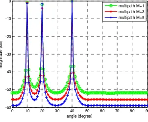
Example 1: In this example, we examine the effectiveness of the method in optimizing for
m
B (r=2,t=1). We assume the received ULA isP=1,h0 =10m. Fig.2 shows the DOA estimation
performance with different number of transmitter antennas. The more the number of transmit antennas has, the better the performance of estimation will be gotten for MIMO radar, especially for the angle resolution. In fact, for the virtual transmitted signalBm, the method by r−t mixed norm
optimizing can obtain the largest transmitter multipath variable and reflection coefficient, which will improve the transmitted signal power.
0 10 20 30 40 50 60 70 80 90 -60
-50 -40 -30 -20 -10 0
angle (degree)
m
a
g
n
it
u
d
e
(
d
B
)
multipath M=1 multipath M=3 multipath M=5
Figure 2. Estimation performance with different number transmitter antennas.
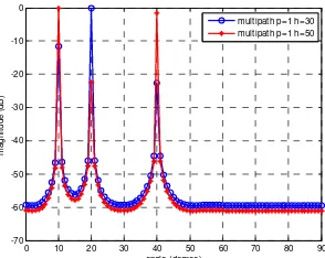
Example 2: In this example, we examine the effectiveness of the peaks searching method in
optimizing for p
G . We assume the transmitter antennas is M=5. Fig.3 shows the spatial spectrum function at different receiver sub-array. In the case of h=30m, the DOA estimation performance at
1=10
θ and θ3=40
is relative poor; Likewise, In the case of h=50m, the DOA estimation performance
at θ2=20
[image:4.612.229.380.489.614.2]
0 10 20 30 40 50 60 70 80 90 -70
-60 -50 -40 -30 -20 -10 0
angle (degree)
m
a
g
n
it
u
d
e
(
d
B
)
[image:5.612.231.378.66.183.2]multipath p=1 h=30 multipath p=1 h=50
Figure 3. Estimation performance at different receiver sub-array.
[image:5.612.236.375.340.450.2]Example 3: In this example, we examine the estimation performance by the RMSE versus SNR. In
Figure 4, we assume the transmitter antennas is M=5. In the case of P=1,h=0m, we only consider the
transmitter multipath variable and the performance in multipath environment is better than in non-multipath environment, especially under relatively low SNR, which illustrates that the method in optimizing for Bm can improve the DOA estimation performance by using the transmitter multipath
signals power; In the case of P=1 ,h=30m, since the receiver multipath variable at some angle is
very little (Fig.2), the performance is poor. However, In the case of P=3,h=10 :10 : 30m, we can select
the most effective receiver multipath variable from different receiver ULAs by the peaks searching method and the estimation performance is the best.
-15 -10 -5 0 5 10 15 10-2
10-1 100 101
SNR
R
M
S
E
non-multipath multipath P=1 h=0 multipath P=1 h=30 multipath P=3 h=10:10:30
Figure 4. RMSE versus SNR for DOA estimation performance.
Conclusion
In this letter, we have proposed a novel DOA estimation method, which can take advantage of the multipath echo power. The method can avoid the effects of different multipath variable and targets glint, which results in the spatial diversity for transmitter and receiver. We demonstrate our method has much better performance in contrast to the non-multipath environment or with the increase of the transmit antennas or ULA. The target tracking and positioning in multipath environment will be considered in near future.
References
[1]E. Fisher, A. Haimovich, R.S. Blum, D. Chizhik, L. Cimini, and R. Valenzuela, “MIMO radar: an idea whose time has come,” in Proc. of the IEEE Radar Conference, pp.71-78, Apr 2004.
[2]E. Fisher, A. Haimovich, R.S. Blum, L. Cimini, D. Chizhik, and R. Valenzuela, “Spatial diversity in radars-models and detection performance,” IEEE Trans. on Signal Processing, vol. 54, pp. 823
-838, Mar 2006.
[3]P. Stocia, J. Li, and Y. Xie, “On probing signal design for MIMO radar,” IEEE Trans. Signal
[4]I. Bekkerman and J. Tabrikian, “Target detection and localization using MIMO radars and sonars,” IEEE Trans. Signal Process. vol. 54, pp. 3873-3883, Oct. 2006.
[5]H. Lehmann and E Fishler, “Evaluation of transmit diversity in MIMO-radar direction finding,”
IEEE Trans. on Signal Processing, vol. 55, pp. 2215-2225, May 2007.
[6]J. Liu, Z. Liu and R. Xie, “Low angle estimation in MIMO radar,” Electron. Lett, vol. 46, no. 23,
pp. 770-771, Nov 2010.
[7]A. Roshanzamir, M. H. Bastani, “Multipath effect on false peaks in covariance based MIMO radar beam-pattern design,” 14th international radar symposium, pp. 970-975, 2013.
[8]H. Jiang, J. K. Zhang, and K. M. Wong. “Joint DOD and DOA Estimation for Bistatic MIMO Radar in Unknown Correlated Noise,” IEEE Trans. Vehicular Technology, vol. 64, no. 11, pp.
5113-5125, Dec 2015.
[9]X. Zhang, L.Y. Xu, L. Xu and D. Xu, “Direction of Departure (DOD) and Direction of Arrival (DOA) estimation in MIMO radar with reduced- dimension MUSIC,” IEEE Communication Letters,
vol. 14, no. 12, pp. 1161-1163, Dec 2010.
[10]G. H. Zhao, G. M. Shi, and F. F. Shen, et.al. “A Sparse Representation- Based DOA Estimation Method with Separable Observation Model,” IEEE Antennas and Wireless Propagation Letters, vol.