2016 Joint International Conference on Artificial Intelligence and Computer Engineering (AICE 2016) and International Conference on Network and Communication Security (NCS 2016)
ISBN: 978-1-60595-362-5
Study on the New Compound Control Method of Three-phase
Voltage Source PWM Rectifier
Ying-Li WANG
a, Chao TIAN
b*, Jing GUO
cHarbin University of Science and Technology, Harbin,China
a[email protected], b[email protected], c[email protected]
*Corresponding author
Keywords: PWM Rectifier, PI Control Method, Fuzzy Control, Feed-forward Compensation, Quasi-PR Control
Abstract. Since the three-phase voltage source PWM commutator is hard to obtain favorable accommodation effect under larger disturbance and variational controlled objects when traditional PI control method is used. This paper comes up with a new type double closed-loop compound control method on the basis of traditional double closed loop control method, that is to say the combination of PI control and fuzzy control is applied to outer voltage control, and the load current is served as forward-feed compensation, inner current ring uses the PRcontrol method. By means of MATLAB/Simulink emulation, the results show that the system not only has a favorable steady-state performance, but also strong robustness to external disturbance, which could verify the feasibility of this control scheme.
Introduction
Three phase voltage source PWM rectifier (VSR) has many excellent properties, such as adjustable high power factor, low harmonic content, bidirectional energy flow and so on [1], it has been highly valued by researchers from all over the world. At the same time VSR also achieved good application prospects. But with the deepening of the PWM rectifier research in recent years, the traditional PI control method[2-3] has been difficult to achieve further breakthroughs in dynamic and steady-static control performance. Based on this, the paper proposes a novel dual closed-loop hybrid control method. Combining PI control with fuzzy control[4]. The electric current loop is a quasi-PR control method with good tracking performance for the sinusoidal AC. The compound control method can not only improve the accuracy of the DC voltage control and anti-disturbance capacity, but also can be implemented quickly tracking current, in order to obtain high quality network-side current waveform.
In this Article, the working principle and mathematical model of thee-phase VSR are analyzed, and the control block diagram of the whole system is given. And the Matlab/Simulink simulation experiment was carriedout, which verifies the correctness of the new control method.
Control Structure and the Mathematical Model of Three-phase VSR Topological Structure
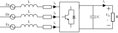
[image:1.612.214.407.674.728.2]The three-phase VSR topological structure is shown in figure 1, , , are epresent input phase voltges, , , are three-phase AC current; L is AC side filter inductor, is equivalent resistance; C is DC side voltage capacitor, is load resistance; is load current.
Mathematical Model
Aiming the three-phase VSR, the mathematical model of the rotating d-q coordinate system can be obtained by the Parker transform and Kirchhoff's Law[5]:
(1)
The transformation matrix between the two-phase rotating coordinate system and the two-phase stationary coordinate system is:
(2)
The voltage equations of the three-phase VSR two-phase stationary coordinate system can be got from the formula (1) and (2):
0
0
(3)
Novel Compound Control Method of Three-phase Voltage Type VSR
Three-phase voltage type VSR control system is designed with double closed loop control structure, which is the voltage outer loop and current inner loop. Its control requirements are: First, The DC side voltage can be quickly maintained to the given value in the case of overcome load and parameter fluctuations; Next, it not can make the rectifier run in unit power factor, but also has good dynamic and static performance and robustness. In order to meet the above requirements, this paper proposes a new type of double closed loop compound control scheme.
Based on the Current Control of Quasi-PR
The quasi-PR control can make the zero error tracking of the sinusoidal current signal. Transfer function is:
(4)
Considering the completely symmetrical at α axis and β axis,now α axis is to be analyzed,we can know:
∗ (5)
G ∗ (6)
L ∗ (7)
Through the above analysis, we can design a regulator M to control the current, that is PR controller. According to equation (3), After ignoring the resistance of the filter inductor, Can get
∗
∗ (8)
In the formula is the proportion coefficient, its value becomes larger, it will enhance the anti-interference ability of system; is the resonance coefficient, and its value can eliminate the steady-state error; is the cutoff frequency, its value becomes larger, will lead to the gain and bandwidth of regulator increased; is resonant frequency.
DC Voltage Output Control Based on Fuzzy PI Control and Load Current Feed Forward Control
Fuzzy PI Controller Design. The advantage of fuzzy control is that don't need to know the precise mathematical model of controlled object, and can get a very good response and adaptability. In this article, fuzzy control and traditional PI control are combined, that is fuzzy PI control,which has high accuracy and robustness, The control principle diagram is shown in figure 2:
t e
[image:3.612.92.288.67.113.2]d d
Figure 2. Principle Block Diagram of Fuzzy PI Control.
[image:3.612.206.419.271.343.2]Load Current Feed-forward Control. According to the analysis of the last section, we could know that outer voltage loop’s could improve the dynamic performance of the system if the fuzzy PI control is adopted. However, under the external variant conditions, the fluctuation of DC side’s voltage is obvious and it is difficult to reach the given values. Yet this problem can be solved by the load current forward-feed compensation method that mentioned in this section. This method can enhance the inhibiting ability to external distubance,and control block diagram is shown in the figure 3.
S
C 1
Figure 3. Control Block Diagram of Transfer Function of Load Current Feed-forward.
In figure 3, is transfer function of control links, is transfer function of converter. In general, it can be regarded as a one order inertial element within a fast time constant,
1
⁄ , among them, k is the proportional constant, T is time constant, is the transfer function of the load current forward-feed link.
[image:3.612.219.399.483.544.2]Simulation Comparison and Analysis
The theoretical analysis are used on the double closed loop new compound control method in front of the article, Now using the simulation tool Matlab[6] to simulate the new compound control method mentioned in the text. Simulation model of the power tube trigger signal modulation metod is SVPWM.
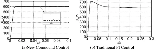
(1)When the given DC voltage mutates from 600V to 700V,figure 4(a) and figure 4(b) presents two DC side’s voltage waveform. Analyze the two groups of simulation waveform figures, we could know figure 4(a)shows that new compound control method adopted can obtain high accuracy of voltage waveform control, short accommodation time and nice dynamic performance. Figure 4(b) illustrates that PI control could eventually be stable on new variation values though, the speed of stabilization is relatively slower than the former and overshoot is larger a bit, control effect is not as good as the former.
[image:4.612.164.447.236.329.2](a) New Compound Control (b) Traditional PI Control
Figure 4. Output Waveform of DC Side Voltage at DC Given dip Instant.
(2)When harply reduces from 50Ω to 30Ω,we could acquire two DC voltage waveform, as shown in figure 5 (a) and figure 5 (b).From figure 5 (a) we could know that, when a mutati-on is carried on the load at 0.05 second, the DC side’s current which is adopted compound control method could besteady fairly fast. When the waveform of mutation point voltage is Ezoomed, we know that it could reach given value 600V without any second after load sudden change, and the control effect is good. From figure 5(b),under PI control method, DC side’s output voltage stabilization toward given values is significantly slower than the former and it needs longer time.
(a)New Compound Control (b) Traditional PI Control
Figure 5. Output Waveform of DC Side Voltage at Load Dip Instant.
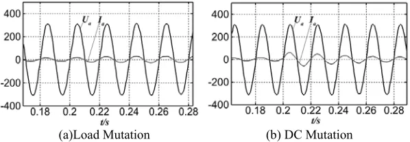
[image:4.612.151.461.462.561.2](a)Load Mutation (b) DC Mutation
Figure 6. A-phase Voltage-current Waveform Based on New Compound Control Strategy.
Conclusion
(1) In this paper, the Fuzzy Control technology is combined with the traditional PI control, then plus the load current feed-forward compensation control method characterize with the resistance of disturbance, which could carry compound control through the outer voltage loop and make the output voltage of direct current side gain higher control precision and robust disturbance rejection character.
(2) In this paper, PR control method is used for current loop, which enable the floating track control acted on sinusoidal alternating quantity, thus could overcome the shortcoming that traditional PI control cannot control the alternating current component accurately, furthermore, PR control method has avoided the fussy decoupling process when PI control is adopted. It shows that the excellent performance when PR control is used in the current loop control.
(3)According to the simulation waveform of new compound control method we figure out, in the terms of traditional PI control, overshoot volume is low, accommodation time would reduce a lot when external conditions are mutated and more resistance in the disturbance rejection capacity. And it combines with feed forward control method, DC side’s voltage has high control precision and fast dynamic response, the entire system obtains favorable dynamic and steady-state characteristics. Meanwhile, it also provides reference frame and significance for hardware device design and the problem-solving toward the future power electronic switch control technology.
Acknowledgement
This research was financially supported by Natural Science Foundation of Heilongjiang Province of China (General Program) (E201235).
Reference
[1]Zhang Chongwei, Zhang Xin. Rectifier and its control [M]. Beijing Machinery Industry Press. 2003.
[2]Zheng Zheng, Tao Haijun. Fuzzy self-tuning adaptive PI adjustment in three-phase PWM rectifie [J]. Electrical Applications, 2005, 24(9): 65-68.
[3] Zhang Yi, Wang Zhiqiang. Three-phase voltage source PWM rectifier based on fuzzy PI [J]. Aviation Precision Manufacturing Technology, 2012, 48(1): 26-29.
[4]Liu Zijian, Wu Min, Chen Xin, et al. Hybrid control schemefor threephase voltage source PWM rectifie [J]. Electric Drive, 2010, 40(9): 20-23.
[5]Hong Naigang. Modeling and Simulation of power electronics and Motor control system. Beijing Machinery Industry Press, 2010.