rh-;'
HEWLETT~~
PACKARD
Rosevil1e Networks DivisionLocation Code: 52-7560
Project Number: 27114B
Septem ber 1, 1989
Project Manager: John McHugh Product Manager: Bill Wang Development Engineer: Pery Pearson
Developrnen t Engineer: Thang Le Diagnostic Engineer: Bill Hoope.r Production Engineer: Ke.n Konesky
Preliminary
Revision 1. 0 11/14/88 Revision 2.001/27/89 EDITING HISTORY:
10/24/88: Outline of ERS (TL)
11/04/88: Preliminary description of registers (TL)
11/14188: Preliminary ERS (TL)
11/17/88: Correct A28/B28 pin swap mistake
Correct set/reset definition for DEND and ATTN Add info about single-ended termination
12/08/88: General correction based on ERS review of 11/29 12/09/88: Change DEND/CEND on 27114B to PEND/HEND
Define FP data to be non-inverted
01/20/89: Drop DIAG bit, invert sense of PZERO bit in reg7 to become NZERO bit, swap header blocks
+/-01/25/89: Define FP data to be inverted (comp. with 27114A) Clarification of EDGE and LOAD bits
03/28/89: Proof-read and corrections made for grammar and technical accuracy.
NOTE:
This document is strictly an external reference specification for the 2 7114B card. It only specifies what is seen and observable at its interface points: the CIO backplane and the parallel frontplane interface.
For more information as how it operates in a system, the readers must confer with other documents: HP-CIO Standard Document, the respective driver's ERS etc ...
Contrary to the expectation of some readers, this document is not intended to be used as an ERS for the
GPIO product which consists of both a hardware (card) and a software (driver) product. As a product, some of the card's behaviors will be greatly influenced by how the driver is written. That kind of information is to be covered in another document which describes the hardware/software interaction.
It is assumed that the reader is familiar with the CIO standard
currently available as a set of 12 files:
~IN_T_RO_D_U_C_T_IO_N
______________
~I~IIII~
The 27114B is a 16 bit parallel device adapter for the CIO channel. It has a 64 level FIFO used to buffer data between the CIO backplane and the adapter's frontplane interface. A counter is provided to allow an exact number of handshakes to take place. The 2 7114B can interrupt the host in various situations: end of count, end of handshake (from a peripheral) or a peripheral attention.
The 2 7114B is intended to replace the 2 7114A to remedy some of its deficiencies:
*
Insufficient grounding for single-ended applications*
Vague control of frontplane handshakes due to the presence of a FIFO*
Limited number of frontplane control and status signals*
Limited number of frontplane handshake modes*
Lack of features which allow asynchronous termination of input/outputSome of the features which are removed from the 2 7114A are:
'*
Backplane parity option'*
Pass-through frontplane parity option'*
Testhood detection capability (not available to user's program)Besides the above changes and deletions, the following changes should also be noted for the new design of the AFI card:
*
The use of synchronous state machines throughout (no delay lines, and no RC time delay circuits)'*
A degradation of frontplane handshake performanceAs for compatibility, the 27114B should be fully compatible with the 27114A when it is used with previously released driven (1.0 through 3.0 venions of the HP-UX/Series 800 operating system). The
27114B can be used with the old single-ended cables (but not recommended for new applications).
Since the 271 14A's on-line diagnostic is very specific to the 27114A hardware, it will not be compatible with the new 27114B hardware. To diagnose 2 7114B cards used in systems which have older drivers and diagnostics, the diagnostic must be updated.
'""'--T_ER_M_I_NO_L_O_G_V_D_E_F_IN_IT_I_O_NS
_ _ _ _ _
I~~ml~'
2.1 INPUT /OUTPUT DEFINITION
The input direction is defined as the flow of data from the user's peripheral to the system's memory. A read is a transaction which moves data from the 10 card to the CPU.
The output direction is defined as the flow of data from the system's memory to the user's peripheral. A write is a transaction which moves data from the CPU to the 10 card.
2.2 WORD, BYTE AND TRANSFER
Word and byte have their usual meanings of 16 and 8 bit data units (the 32 bit word definition used by the Spectrum program is not used here since it is always easier to say 'word' than 'half word').
Since the 2 7114B's data path is 16 bits wide, it is sometimes confusing to describe the amount of data being tr-ansferred as N*2 bytes or N words. The rest of this document will always assume that the 27114B transfers data in the 16 bit mode. Each transfer is therefore equivalent to one 16 bit word.
2.3 LITTLE/BIG ENDIANS
This document uses the normal convention of 0 being the least significant bit in any data or address field.
2.4 LEADING/TRAILING EDGES
As a signal changes from one level to another level, it is defined as the leading edge if the change allows the signal to be in the asserted state. When a signal changes from the asserted state to the deasserted state,
the edge is called a trailing edge.
2.5 CIO INVERSION OF LOGIC
DATA INVERSION:
This version of the ERS defines all frontplane signals such that a 0 in the user's program domain will correspond with a low at the front plane (no logic inversion for frontplane outputs and inputs). This is applicable to both the data and the control/status lines.
ASSER TION/DEASSER TION:
A signal is in its assertion condition when it is at the level which causes a result to happen. It is in its
deassertion condition when it is at the level which cannot cause a result. These levels can be low or high
(electrically), 0 or 1 (logically). Clarifications will be attempted in the rest of this document to qualify an
assertion condition as either low true or high true.
LOW/HIGH:
Low means the voltage is at a TTL low level, nominally below 0.8 Volts. High means the voltage is at a TTL high level, nominally above 2.0 Volts. These will be used to indicate the conditions of various circui ts on the 27 11 4 B hard ware.
0/1:
o
means a false logic in the program domain. 1 means a true logic in the program domain. Whendescriptions are given in 0 and 1 or true and false, these are described in the program domain.
SET /RESET(CLEARED):
Set/reset conditions are usually used to describe the state of flipflops or register bits on the 27114B. A
set condition means the flipflop is in the asserted state and is a 1. A reset condition means the flipflop is
in the deasserted state and is a O.
CONVENTION:
*
Assertion/deassertion are always qualified with low/high or0/1 or false/true
*
Hardware description uses low/high*
Logic description in the program domain uses 0/1 or false/true2.6 GLOSSARY
~C_ON_F_'G_U_R_A_T_IO_N
______________
~I~~HI,
3.1 CONFIGURATION FEATURES
To customize the 2 7114B card for any application, the user has the following choices:
*
single-ended (unbalanced) or balanced differential cable*
desirable cable length (3m and 12m standard)*
the number of control lines vs other output features likeHEND and PDIR
*
the number of status lines vs other input features likePEND and ATTN
*
the length of PCTL high and low time*
the hysteresis time of the PFLG signal·3.1.1 Single-ended/Differential Ouputs
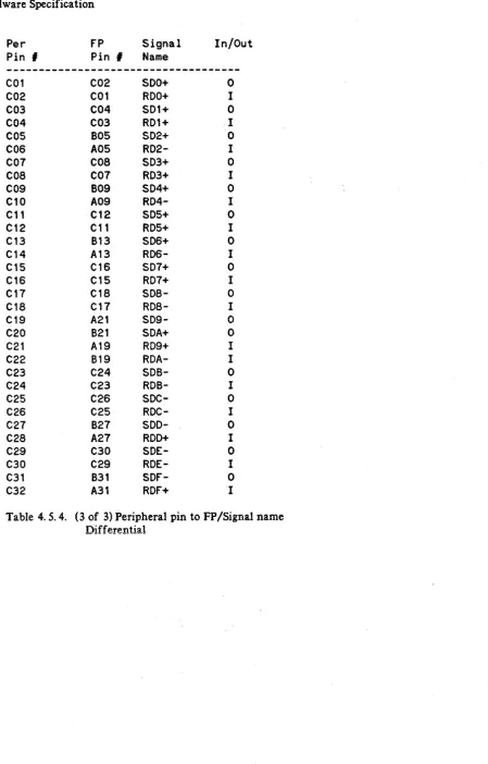
To provide a good solution to single-ended cable applications, there is a jumper block arrangement on the 27114B card which allows the user to dynamically reconfigure the connection of signals in a 27114B cable.
Each signal received or driven by the 27114B is available as a pair of differential signals, an inverting (-)
and a non-inverting (+) output. If the input to a line driver is at a TTL high level, the (+) output is at a
high level and the (-) output is at a low level. If the input is at a TTL low level then the (+) output is at a
low level while the (-) output is at a high level.
The 27114B will be supplied with only one cable type, differential, which has 47 twisted pairs. The previously available hingle-ended cables are not recommended for use with the 27114B. They are still
compatible with the 2 7114B but for a new application, the 47 twisted pair cable is recommended since it
should outperform the single ended cable in all aspects of electrical characteristics.
2
Row G
* *
* * * *
*
* *
*
* *
*
* *
*
*
*
*
* *
*
* *
Row J-
* *
*
*
* *
*
* *
*
* *
*
*
*
*
*
*
*
* *
*
*
*
Row C- *
*
*
*
* *
*
*
* *
* *
*
* *
*
*
*
*
* *
*
*
*
Row G
*
*
*
*
*
* * * * * * * *
*
*
*
* * * *
* * *
*
Row J+
* * * *
* *
*
* *
*
* *
*
* *
*
* * * * *
*
* *
Row C+
*
*
*
*
* *
*
* *
*
* *
*
*
*
*
* * * * * * * *
1Left 1/2 of jumper block
92
Row G
*
* *
*
* * * * * * * *
*
*
*
*
*
* *
* * * ,
# Row J-*
*
*
*
*
* *
*
* * * * *
*
*
*
**
*
*
*
* , ,
Row
c-
*
* *
* *
* *
* * * *
*
* * *
*
* *
*
*
*
* , ,
Row G
* * *
*
* * * * * * * *
*
* *
*
*
*
*
*
*
*
# IRow J+
*
*
*
*
* * * *
*
*
*
* *
* *
*
*
*
*
*
*
*
# IRow C+
* * * *
*
*
*
*
*
*
* *
*
* *
*
* *
*
* *
*
# #91
Right 1/2 of jumper block
Only 46 of the 48 columns are actually used. The rightmost two columns are not used. Markings are
done for jumpers 1, 2, 91 and 92. Also marked is 0, 1, and C- for the upper rows and 0, J, and C+ for the
lower rows.
All pins on the G rows are grounded. All pins on the 1+/1- rows are connected to the (+)/(-) signals on
the connector, respectively. All pins on the C+/C- rows are connected to the driver/receiver packs'
output/inputs (+)/(-), respectively. There is a space between the C+ and lower 0 rows to prevent
unintentional shorting of C+ signals to ground. 12 jumper blocks are supplied. Each block can be used to connect 8 sets of pins on adjacent rows. 6 of these, stacked end to end will allow one entire row to be
shorted to an adjacent row (1+ to either C+ or G). The other 6 are used for the other set of signals (J- to
either C- or 0).
To configure in the differential mode, each signal from the connector on the J+ row must be connected to
a package pin at the same column on the C+ row. Likewise, signals on the J - row must be connected to package pins on the C- row. Therefore signals go straight between the driver/receivers and the connector pins (1+ to C+, J- to C-).
To configure in a single ended mode, one rail of the connector pins (either J+ or J-) is grounded (connected to G), leaving the other set of pins connected straight to the driver/receiver packs. For example, in the case of a low true connection, row J+ is connected to row G and row J- is connected to row C-. In this case, (-) signals go straight to the cable but the companion wires on the cables (connected to J+ pins) are grounded. This arrangement maintains a good degree of noise tolerance for all single ended signals.
DIFFERENTIAL: Connector - Empty row - Jumper block - Empty row - Jumper block
LOW TRUE: Connector - Empty row - Jumper block - Jumper block - Empty row
HIGH TRUE: Connector - Jumper block - Empty row - Empty row - Jumper block
3.1.2 Line Termination
To properly terminate the cable in the different frontplane connection modes, the termination load and reference packs must be installed according to the following scheme.
IDENTIFICATION OF PIN 1 OF TERMINATION SOCKETS: There are three 20 pin termination sockets on the 2 7114B card. Pin lof these sockets has a square' pad on the printed circuit assembly board. All other pins have a round pad. Pin 11 is the pin which diagonally opposes pin 1. Pin lOis on the same side of pin I but at the other end of the package. Pin 20 is the other corner pin.
IDENTIFICATION OF PIN 1 OF SIPs: The SIPs (single in-line packages) have 10 pins in one straight line. Pin 1 is the first pin on the end which is usually marked with a solid band or a dot.
IDENTIFICATION OF PIN 1 OF DIPs: The DIPs (dual in-line packages) have 16 pins arranged as two rows of 8 pins. Looking from the top, there is usually a dot at one corner or a notch at one end of the pack. The dot marks where pin 1 is. If the DIP is positioned such that the notch is up, pin I is the first pin on the left row from the top.
DIFFERENTIAL (BALANCED MODE):
3 16-pin DIPs (I 81 0-0964) are required. These must be plugged into the three termination sockets such that their pin 1 goes to pin 2 of the socket (the four corner pins of the sockets are not used).
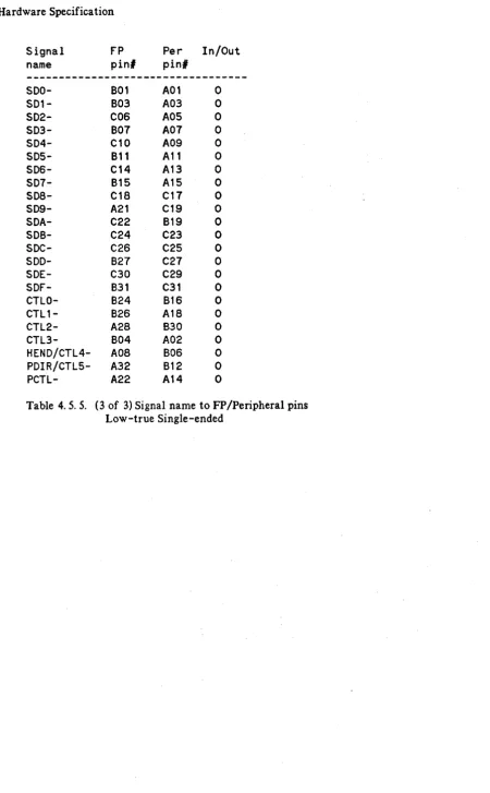
LOW-TRUE SINGLE-ENDED (UNBALANCE MODE):
3 10-pin load SIPs (1810-0677) and 3 10-pin reference SIPs (1810-0906) are required. Pin 1 of the load SIPs must be connected to pin 20 of the termination sockets. Pin 1 of the reference SIPs must be connected to pin I of the termination sockets.
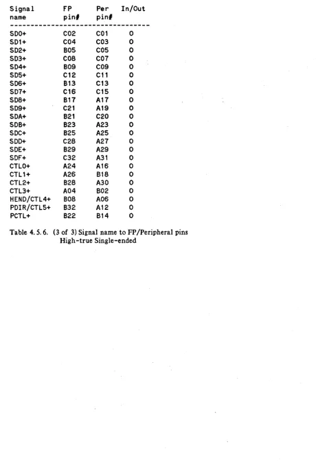
HIGH-TRUE SINGLE-ENDED (UNBALANCE MODE):
3 10-pin load SIPs (1810-0677) and 3 10-pin reference SIPs (1810-0906) are required. Pin 1 of the load SIPs must be connected to pin 1 of the termination sockets. Pin 1 of the reference SIPs must be connected to pin 20 of the termination sockets.
3.1.3 Cable length
There are currently two cable lengths available: 3 m and 12 In. These should be adequate for most applications. Note that the 12 m cable should not be used in single-ended applications due to the inherent low noise margin of the single-ended signals.
It should be noted that the DuPont company, Cumberland, PA. (USA) has been wining to manufacture the differential cable in any cable length. Inquiries should be referenced to HP's drawing numbers,
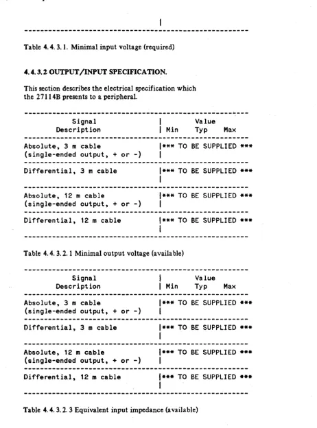
***
SAFETY NOTE****
The overall length of the 27114B cable cannot exceed a length at which the total shield path resistance exceeds 100 milli-ohms. This shield path includes the shield of the cable from one end to another, plus the shield trace on the 2 7114B and the shield connection on the host (typically between the backplane's shield connector pin and the safety ground plug of a three prong plug of the system).
***
TO BE VERIFIED***
The shield path resistance for a 12 m cable meets the above specification for all existing supported systems.
The 27114B product is tested with two different cable lengths: 3 m and 12 m. Note that if there is
excessive signal reflection, certain cable lengths may be much more sensitive to self -induced noise. From
an electrical performance point of view, it is projected that the cable could be extended to a length longer
than 25 m. If this is the case, the user must be assured that all electrical specifications are still within the
required ranges (voltages) timing etc ... ).
Due to a restriction of resources, the project team will not be able to guarantee cables longer than the supported 12m length.
3.1.4 PCTL Pulse Extension
One of four jumper positions (Jl through J4) must be selected to insert a delay in the PCTL path. The
following table illustrates how:
Jumper position selected
J4 (P 3)
J3 (C 2)
J2 (T 1) J1 (l 0)
Delay added to peTl's transition high to low
I
low to high150 ns 50 ns 100 ns 50 ns 50 ns 50 ns
0 ns 0 ns
Note that the assertion state of PCTL is low.
Only one jumper can be installed in the a bove four posi tions.
There will be an indeterminate result if more than one position has
a jumper in it.
3.1.5 PFLG Filtering
Jumpers J 5 through J 8 can be used to select a filtering effect for the PFLG signal. The following table
Jumper position selected
J8 (p 3)
J7 (f 2)
J6 (L 1)
J5 (G 0)
PfLG sync time
4 clocks (150 - 200 ns) 3 clocks (100 - 150 ns) 2 clocks ( 50 - 100 ns) 1 clock ( 0 - 50 ns)
As PFLG is an asynchronous signal to the card, it is always sync'ed first before being used by the state machine on board the 27114B.
The minimum selectable value is one clock. The 50 ns associated with this (as shown in the table) means
that if PFLG is stable for at least 50 ns, it is guaranteed to be seen by the 27114B. It does not mean that
the card will ignore a PFLG which is stable for less than 50 ns. The exact timing of the PFLG signal will determine whether the change could be seen or not.
The other 3 positions (J6 through J8) require the change in PFLG to be solid for the appropriate amount of time as shown in the previous table. For example, if jumper position J7 is selected, a change in PFLG is
guaranteed to be recognized if it has happened more than 150 ns. It could also be recognized if it has
been more than 100 ns but this is not really guaranteed (depending upon the actual timing of PFLG
versus the 2 7114B's sampling clock). If the PFLG signal temporarily reverses to its original level for 15
ns or more,
***
CHECK THIS 15 ns NUMBER****
the filtering circuit resets its timer and the change is considered to start after the temporary reversal.
This filtering selection should be very effective in filtering out false triggers to the PFLG circuit should
the application exhibit excessive noise on that signal (mostly due to cross-coupled noise or line reflection).
3.1.6 Control/Status Options
The user has the option to configure the frontplane control and status lines. Control lines are outputs which the user's program can control directly, independent of the state of the driver or the hardware. They are programmable directly as control bits in registers in the hardware. Their states do not affect the
operation of the rest of the 2 7114B hardware. Status lines are input lines which can be sampled and read
directly as bits in status registers on the 2 7114B hardware. The states of the status inputs do not affect the function or condition of the rest of the hardware.
The 27114B has six control outputs. Four of these are permanently assigned as controls, and two of them
can be reassigned to carry two different functions: HEND and PDIR. The card powers up with the HEND
and PDIR functions selected. Both of these function outputs are selected via the same option bit; they cannot be selected individually. The HEND output is asserted with the last output word or after the last input word. The PDIR output reflects the state of the direction control bit on the AFI card
circuit can be used by a peripheral to terminate a transfer prior to the exhaustion of its count. The
PEND needs to be asserted high with the last input word or after the last output word.
3.2
CONFIGURA TION AT SHIPPING
As shipped from the factory, the 27114B will be configured for a differential application. It will have a 3 m cable and will power up like a 27114A card. The PCTL pulse extension is set at 0 ns. The PFLG hysteresis selection is set at 0 ns.
3.3
SYSTEM CONFIGURATION
Due to the restriction placed on CIO level 1 cards (the AFI is a level 1 card), the AFI card can only
respond to group 0 pollings. This requires that the card be placed in slot 0 through 7 of any CIO
backplane.
~HA_R_D_W_A_R_E_S_P_E_C_IF_IC_A_T_IO_N
________
~I~~~
4.1 GENERAL HARDWARE OVERVIEW
The following measurements are for the main PCA (less cable and test hood):
*
Size: 0.171 m (Width) X 0.174 m (Depth) X 0.0134 m (Height)Height is measured from top surface of PCA to top of tallest component (SIP, 1810-0677).
*
Weight: approximately 0.300 Kg*
Current consumption: approximately 2 A (5 V only)*
Operating environment: HP Class B4.2 BACKPLANE SPECIFICATION
LEVEL 1 CARD:
The 2 7114B AFI card is a CIO level 1 card. This renders the card different than most (if not all) other CIO cards. The CIO's level 2 protocol is not applicable to this card.
CIO BACKPLANE ADDRESSING:
4 CIO signals are used to address 1 of 16 registers on the 2 7114B card: BP I/CBYT /CEND/BPO (arranged
in this order of significance). Note that while some other CIO programming documentation (including the CIO standard) may have a different address naming convention, the method used on this module was adapted after that which was originally used on the series 500 machines.
SLOT LIMITATION:
As noted earlier, the AFI is a level 1 card and therefore restricted to group 0 polls. Consequently, it must
be in a slot in the range of 0 through 7. This restriction is imposed due to the design of the TTL channel
adapter for the series 840/850 machine.
COMPA TIBILITY:
The AFI 2 7114B is designed to be compatible with the CIO standard (version 2. 2 11/1986). It should be
compatible with all existing CIO backplanes on Series 800 systems.
CIO BACKPLANE PERFORMANCE:
Depending on the number of data words presently stored in the FIFO on board the 27114B, the backplane
in the output direction, bursting is allowed whenever there is 0 through 55 words in the FIFO. In the input direction, if there are more than 8 words in the FIFO, bursting is allowed. Other than those, data will be handled on a word. by word basis with a poll between them. This approach serves to simplify the backplane interface (eliminating the 4 external latches and the associated state machine to control them in the old 27114A) and maintain approximately the same burst transfer speed.
CIOPARITY:
Since there are no real demands for the CIO parity function and it takes at least 3 chips to support, this feature is not supported on the 27114B.
4.3 MID-PLANE SPECIFICATION
4.3.1 Reset
CIO RESET:
Upon power up or the assertion of the /RST signal on the CIO backplane, the 27114B goes into the hard-reset state. Until it is removed from this state, all normal accesses are ignored. Only a write to the
data register (register 0) with a 1 in the data bit corresponding to the slot which the 2 7114B is in would
bring it out of its hard -reset state.
A hard-reset resets the ARE flipflop (interrupt is disabled) and sets the RESET flipflop. Both of these are
also accessible with writes to register I (CIO CONTROL register).
CARD RESET:
When the RESET flipflop is set, the 2 7114B is in the (soft) reset state. This resets all frontplane state
machines and presets all write data register (register 1) bits to 1. The RESET flipflop does not affect the
ARE flipflop.
FRONTPLANE RESET:
The FIFO is reset with the CRFF bit in the write register 7 (AFI CONTROL register). This means it is
also reset with a reset condition or a hard-reset condition. As long as the CRFF bit is a I, the FIFO
remains in the reset state.
STATE MACHINE RESET:
The state machine is also reset with the CRFF bit like the FIFO. As explained in more detail later on, the
state machine controls all the handshakes between the FIFO and both the frontplane and the backplane
circuits. The power-up/reset default state is such that the 27114B:
*
guarantees to bring its PCTL to a low deassertion stateimmediately. PCTL is kept in this state until the 2 7114B is programmed by the host for a transfer.
*
asserts the HEND output to a low level*
does not take any handshake from a peripheral untilINTERRUPT RESET:
-'.
The interrupt circuit consists of two flipflops: ARE (enable) and ARQ (register). ARE is reset by a hard reset condition only. ARQ is reset with any read from register 9 (CIO STATUS register).
4.3.2 FIFO
The 27114B uses a FIFO to improve data flow between the front plane and the backplane. The FIFO is a 64 level deep, 18 bit wide FIFO. It is built with 2 CY7C409 64 X 9 FIFO chips from Cypress Semiconductor.
The FIFO is used in a half-duplex mode. Depending on the direction of data transfer, it can take data from the frontplane or the backplane and output data to' the other party. 16 bits are used to carry data between the frontplane and the backplane. The 17th bit is used exclusively for the PEND signal. The PEND's direction of flow is from the frontplane to the backplane in the case of input transfers. For output transfers, the PEND circuit bypasses and does not use the 17th bit of the FIFO. The 18th bit is used to carry the HEND signal from the CIO backplane to the frontplane. It is useful only in output transfers. For input transfers, the HEND circuit does not use the 18th bit of the FIFO.
The CY7C409 FIFO chip has a feature which facilitates the design of the 27114B. It has two status outputs which indicate whether there is more than 1/8, 1/2 or 7/8 of data being stored in the FIFO. "f;f By
taking advantage of these flags, the bursting feature on the CIO backplane is enabled whenever there is room for at least 8 transfers. As the number of available transfers drops below 8, the bursting feature is turned off, and all transfers are done on a word-by-word basis. In the non-bursting case, a service poll is done between two consecutive transfers (other CIO cards can also be serviced before the next transfer happens). Bursting on CIO allows up to 32 transfers to be done between service polls.
The effective FIFO length in the output direction is 55 levels. Service polls are answered positively only when there are room for 8 words or more in the FIFO. Burst Request is asserted low during all CIO transfers to the 27114B. Due to the delayed response from the CIO handshake state machine, there might be occasionally up to 58 words stored in the FIFO.
The effective FIFO length in the input direction is still 64 levels. Any time the FIFO has less than 8 words, transfers will be done in the non-bursting mode.
Upon a reset condition (CRFF being asserted with a I, soft reset or hard reset), the FIFO is cleared and all stored words (if there are any) are lost; all outputs become low.
4.3.3 Interrupts
ATTN RESET---+---+
I
ATTN --+---+-) ATTN ff
I
>--
ATTN INT
I
I
+---+
PEND RESET ----+
I
PEND ----) PEND ff ----+
PEND INT DIS ---+
) - - -
PEND-+
INT.
I
I
XfER COUNT RST-+
I
I
I
PCTl ---) XfER COUNTER--+
I
>---
XFER
I
XFER INT DIS ---+
INT.
I
I I
+--+-+
I
READ REG. 9 (CIO STATUS)
--->
ARQ
I
WRITE REG. 1 (CIO CONTROL)
--->ARE
I
CIO INTERRUPT
PICTURE: INTERRUPT CIRCUIT ON 27114B
All three sources are OR'ed together such that the first high assertion of the three will set the ARQ flipflop (provided that there is no current reading of register 9, the CIO STATUS register). This action is of the edge-trigger type which means a read of register 9 will clear the ARQ flipflop regardless of the
condition of the three interrupt sources. If ARQ is cleared while an interrupt source is still asserted high,
a second interrupt assertion (high) does not set ARQ again.
If ARE is set (interrupt is enabled), the setting of ARQ brings the 2 7114B into the interrupt state. In this
state, the 27114B drives the ARQ signal on the CIO bus with an open-collector gate. When polled with an attention poll, the 27114B responds via the UAD line on the backplane. Any reading of the CIO STATUS register (register 9) will clear the ARQ flipflop. The ARE flipflop is controllable via bit 0 and 1 of the CIO CONTROL register (register l/write).
PEND INTERRUPT:
The PEND interrupt is enabled. when the PEND option is selected and when the PEND INT _DIS bit is O. Any falling edge of PEND will cause the PEND flipflop to be set. This PEND flipflop remains set until it
is cleared with a 1 in the PEND RESET bit (PEND RESET is also used to disable the PEND circuit). This
action of setting the PEND flipflop is independent of the ARQ flipflop. If it is the first interrupt of the
three, it also sets the ARQ flipflop (if so enabled). The PEND flipflop is not affected by the CRFF bit.
The ATTN interrupt is enabled whenever the ATTN option is selected (power up defaUlt). Any falling
edge of ATTN will set the ATTN flipflop in this case. If the other two interrupt sources are not
c~rrently asserted high at that time, the ARQ flipflop is also set (if enabled). The ATTN flipflop remains set until the ATTN circuit is disabled with a 0 programmed in the ATTN OPTION bit in register B (AFI
CONTROL2 register). The ATTN flipflop is provided to record the interrupt caused by the ATTN input
at the frontplane of the 27114B card. This is most useful when there are multiple interrupts (for example, a short pulse is applied to the ATTN input immediately before or after another on-board interrupt occurrence. The driver should be able to detect that there is an ATTN interrupt and another on-board interrupt).
Note that the ATTN flipflop and the ARQ circuit are independent. A falling edge on the A TIN can set the ARQ flipflop regardless of the state of the ATTN flipflop. Unless the ATTN flipflop is cleared by each interrupt service routine, it is hard to tell if the current interrupt was also caused by the ATTN input if either or both PEND and the transfer counter are found to be the cause of the interrupt. This is
done to allow the 27114B to be backward compatible with the 27114A. In the 27114A-compatible
mode, the A TTN interrupt flipflop remains set indefinitely after the first ATTN interrupt (until a power-up or reset condition is applied to the 2 7114B card).
TRANSFER COUNTER INTERRUPT:
The transfer counter interrupt is enabled with the enabling of the transfer counter and the setting oLthe
ZERO INT _DIS bit to O. As the transfer counter counts down to 0, the Transfer counter interrupt signal
is asserted high. Section 4.3.5 addresses the enable/disable of the transfer counter circuit. To determine if the transfer counter is a possible cause for an interrupt, bit Zero in the read register 7 (AFI STATUS register) can be inspected.
4.3.4 PEND Function
The PEND function is optional. When selected, it allows a peripheral to terminate a transfer even when the tran~fer's count is not a 0 yet. The PEND option on the 2 7114B can be selected with a 0 programmed in the PEND RESET bit of write register B (AFI CONTROL2 register). A write of 1 will reset the PEND flipflop and disable its function. The power up default state disables the PEND option.
For input transfers, the frontplane PEND signal is clocked into the FIFO as the 17th data bit (low bit). Its timing (set-up time and hold time) must satisfy the same requirements as those of the input data words. A low PEND indicates that the peripheral wants to terminate the data transfer with the current data handshake. As the input handshake is completed, the PEND flipflop is set and the frontplane handshake state machine is disabled, preventing further handshakes from happening. As the data word propagates through the FIFO, it shows up eventually at the CIO backplane. As this word is handshaked on the CIO backplane, the CIO's DEND signal is asserted low for the duration of the transfer (with respect to IO_SB of CIO) while the Burst Request circuit is deasserted high, regardless of the condition of the FIFO (it
should have been deasserted anyway). The CIO channel adapter should have the same transfer count as
that maintained on-board the 27114B. The 17th output from the FIFO is designed to be low true to
assure that the CIO's DEND signal is asserted low only when there is an input data transfer.
For output transfers, any time a falling edge is detected on the PEND input (a transition from high to
low), the PEND flipflop is set. This edge can happen any time: during or after a handshake. HoweverJ
after the PEND flipflop is set, the frontplane handshake circuit is disabled. Therefore, if the edge is
detected after a handshake has initiated, the handshake will go through. It is best that the peripheral
To abort the current data transfer on the CIO bus, the 2 7114B fakes a ready for data condition and yanks on the DEND line as the-channel transfers the next word. After the next CIO data output transfer (in case there is still some room in the FIFO) or service poll, the CIO frontplane handshake state machine automatically answers positively to service polls (regardless of the condition of the FIFO) and at the same time, disables the burst request signal. As the CIO does the next output data transfer, the CIO's DEND signal is asserted low to inform the CIO channel that it should terminate the transfer. Note that the actual count maintained by the CIO channel adapter is always bigger than the count maintained by the transfer counter on-board the 27114B since there are some words left dangling in the FIFO (or being lost due to the overflow).
In both cases, the setting of the PEND flipflop can also cause the ARQ flipflop to be set if the PEND
DIs_INT bit is a O. An interrupt could be generated in this case if the ARE flipflop is also set.
Imm.ediately after a CRFF reset, the 27114B asserts the CIO's DEND signal low with any CIO read of the data register since there is no valid data word in the FIFO. Note that the CIO channel is not supposed to
do any data transfer in this case (2 7114B is in the input mode and the FIFO is empty). If there is valid
data in the FIFO, the assertion of PEND depends on whether the PEND feature is enabled and the front plane PEND input was asserted low for that word.
If the 2 7114B's output mode is selected after a reset, the PEND circuit is not asserted until a peripheral deasserts (low) the PEND input.
The driver must reset the PEND flipflop before each transaction if the PEND flipflop was set by a peripheral in the previous operation. This is particularly important to generate a PEND type interrupt and to assure a normal output transfer (output transfers will stop with the first word if the PEND flipflop is still set).
4.3.5
HEND
The HEND option of the 27114B allows the card to signal to a peripheral that the last transfer has happened (input) or is about to happen (output). The HEND circuit is enabled with the PDIR option bit found in the write register B/lower (AFI CONTROL2 register). The power up default state is that this feature is enabled.
When enabled, the output which normally corresponds to the CTL4 control bit is driven according to the state of the HEND circuit. The HEND output is driven by either the 18th data output of the FIFO or the zero count output of the transfer counter.
There is no HEND flipflop to register the fact that HEND is asserted on the frontplane (driving the peripheral). The HEND bit in the AFI STATUS register reflects the state of the HEND output.
The power-up (default) state of HE NO is asserted low. This is due to the fact that the FIFO is cleared to a low level for all of its outputs. HEND is asserted high immediately with the first input transfer (when the data is shifted into the FIFO) or just prior to the availability of the first output data word (with the same set-up timing availability),
with a non-zero value. Consequently, this requires the FIFO to be reset before each output transfer starts so that the HEND output can be initialized to the non -assertion state.
For input data transfers, the HEND signal is asserted low on the frontplane immediately after the last
handshake has started. As soon as the transfer counter reaches zero, HEND is asserted (immediately after the deassertion to assertion edge of the PCTL control output). HEND is normally driven by the transfer counter for input data transfers.
The HEND output remains in the low assertion state as long as the transfer counter's output is a zero. This is true in both input and output data transfer cases. Loading the transfer counter's counter with a non zero value or presetting the transfer counter will deassert the HEND output.
As a product concern, HEND may be left asserted until the next call (this is true in the case that the
driver doesn't bother reloading or presetting the counter at the end of a transaction). If the peripheral
expects a deasserted HEND (high), the card must be reset via a driver call first.
The assertion of HEND does not inhibit the front plane from handshaking. In output transfer cases, this should not be a problem because the CIO has given all the data to the FIFO and all data in the FIFO has been handshaked out so there won't be any more possible handshakes, even if the peripheral wants to do so. In input transfer cases, a HEND assertion condition is normally a result of the transfer counter reaching zero. This later condition inhibits the frontplane handshake circuit. In the rare case described above where the CIO's counter is programmed with a value at least 64 less than that in the transfer counter, the card would continue to handshake as normal.
NOTE: The HEND frontplane signal is not driven in the case where the counter is not used for an input, transfer; for an output transfer without the counter, the CIO channel drives HEND, and for transferS" using the counter (in and out), the counter asserts HEND when the counter reaches zero and PCTL is low. HEND is asserted low prior to the first handshake of a transfer due to its remaining asserted from the end
of the previous transfer; the default state of HEND after a reset or power-up is also a low assertion.
4.3.6 CEND/HEND Interaction
This section illustrates a hypothethical case of two 2 7114B cards being connected to each other and the effect of HEND/PEND between the two cards. 4 cases will be looked at:
SLAVE READS MORE THAN MASTER WRITES SLAVE WRITES LESS THAN MASTER READS
Both cases are similar with the HEND/PEND timing coinciding with that of the data lines. The timing of an output device's HEND has the same set-up and hold time as the last data word and this meets the same requirement for the input device's PEND input. Both master and slave should terminate with their PCTL in the deasserted state and the correct count remainder.
SLA VE READS LESS THAN MASTER WRITES
SLA VE WRITES MORE THAN MASTER READS
This scenario doesn't work. Since the master's HEND is asserted low at the same time as its PCTL's assertion, the slave may. or may not be able to start the acknowleging cycle (due to the finite delay between PCTL and REND). The result is that it is unknown if the master completes the handshake.
4.3.7 Transfer Counter
The transfer counter is a 24 bit counter which can count down (logically) from OxFFFFFF to O. The logical zero output from the counter is actually activated whenever the count is between 0 and OxOOFFFF (65535 decimal). The effective range of the counter is therefore between a maximum of OxFFFFFF (16,777,215 decimal) and a minimum of OxOOFFFF (65535), the first value where the zero count output is activated.
Therefore, it is advisable that all counts should be made with an offset of OxOOFFFF. For example, to
allow 5 transfers to go through the frontplane, a count of 5+0xOOFFFF or OxO 10004 must be programmed in the counter. Once this offset is used, it must be subtracted from a value read from the counter to calculate the exact remaining count.
The counter value is accessible as read/write register A (for the lower and middle bytes) and read/write register B/upper (for the upper byte). The default power up state of the counter is: the counter contains
the maximum count, it is disabled, its interrupt is disabled, and its load control bit is set (to
O.
Thisdefault state allows the counter to be transparent to the rest of the 27114B.
The counter has two parts: a write register which holds a value written to the counter and a counter which does the counting. The value held in the write register remains the same unless a new value is written to the transfer counter circuit. The counter part can count down or it can be loaded or reset.
The counter is controlled by three bits: Count Reset (in write register B/lower, AFI CONTROL2 register), ZERO INT_DIS and Load Count (both in write register 7, the AFI CONTROL register). A 1 programed
. into the Count Reset bit keeps the counter in the reset mode, inhibiting it ~rom counting (this is also the
power up default mode). A 0 programmed in the ZERO INT_DIS enables the transfer counter circuit to set the ARQ flipflop when it counts down to a value in the logical zero range (0 through OxFFFF). The default value for this bit is a 1 (disable). The Load Count bit is used to transfer a value currently stored in the counter's write register to its actual counter (a read register). This bit has a default value of 1. Whenever this bit is a I, the content of the actual counter is the same as the value last written to its write register. This bit should be kept at 0 for the counter to count.
The counter counts down (logically) with each deasserting-to-asserting edge of the frontplane handshake control output PCTL (a transition from a high to a low level). Upon reaching the logical zero count (set when the actual count is within the range of 0 and OxFFFF), the transfer counter disables the frontplane handshake. By reading the contents of this counter, one can determine how many handshakes have actually happened, regardless of the current state of the FIFO. Note that in input data transfers, a logical zero count does not necessarily mean that all data words have arrived in the hosfs memory, just that all
words have been accepted by the AFI card (some of them may still be in the FIFO). Also, in output
transfers, a logicai zero count doesn't mean that the FIFO is empty.
It should be noted here that due to the critical timing required by the front plane handshake circuit, the
It should also be noted that the zero count interrupt happens only when both the count is zero and PCTL is deasserted. That means an interrupt can occur only after the last handshake (with the counter equal to zero) has completed.
In both input and output cases, the HEND output (when the option is selected) is asserted low whenever the transfer counter's output is a logical zero.
The default power up value of the counter is the maximum count. It is recommended that the transfer
counter be loaded or preset before each transaction.
4.3.8 State Machine
A synchronous state machine is used in the 2 7114B hardware to control the movement of data between the frontplane and the backplane. The state machine actually consists of two independent state machines, one for shift-in and one for shift-out.
The shift-in state machine is responsible for controlling the input of data into the FIFO. In output data transfers,it writes a data word into the FIFO every time the CIO channel writes to the data register (it is the responsibility of the CIO channel to observe the service poll result before doing so). In input data transfers, it assumes the duty of frontplane handshaking while also controlling the writing of input data into the FIFO.
The shift-out state machine controls the reading of data out of the FIFO. In output transfers, it controls the handshake circuit as data is read from the FIFO. In input transfers, it clocks a word out after each read from the data register is made by the CIO channel.
The frontplane handshake part of each of these two state machines are disabled whenever one or more"'of
three conditions exists: the word counter's content is a zero, the PEND flipflop is set, or the frontplane· is
disabled.
4.3.9 Miscellaneous
There is no GPIO mode. If there was a GPIO mode, the 27114B would behave as though it had only one level of storage in the FIFO. This perhaps would simplify the interface to a non-intelligent driver. From a system level, the 2 7114B would behave very much like a true GPIO card if the driver were written to take advantage of the on-board transfer counter.
For output transfers, the driver should complete the call only when the frontplane handshake circuit has
stopped (either because of an exhaustive count or a PEND condition) or a time-out has happened. If the
count is less than 64, the driver can elect to do the data moving itself to avoid the unnecessary step of having to set up a Dl\fA transaction for the CIO channel.
For input transfers, it can terminate the call whenever the CIO channel adapter has completed the CIO
DMA transaction. If the transfer count is less than 64, the driver can also elect to do the data moving
itself after the frontplane transaction has stopped.
For read/write of fixed values (like 1 word), the counter really doesn't have to be reloaded every time.
This could save two writes to the card.
There is no support for a frontplane parity option. The available but not officially supported frontplane parity feature of the 27114A was never activated or used. Physical restrictions in the layout of the 27114B prevent this feature from being implemented.
POWER UP INDICATOR:
Some customer feedbacks indicate that there is a need for an output which could be used to indicate that
4.3.10 Register Address Table
Register address table:
NOTE:
*'
Bit N is always less significant than bit N + 1*'
When written down, a bit is always more significant thanbits on its right
BP1
I
CBYT
I
CEND
I
BPO
I
REG
I
I
I
I
Function Read
I
Writeo
X XI
0 10,2,4,61 Input dataI
Output data---o
0 0I
I
Sense Reg.I
CONTROL Reg.o
0I
I
3I
I. D. Reg.HI
A---o
I I 7 1 AFI Sta Regl AFI Cnt Reg.---o
0I
9I
CIO STATUSI
HI
Ao
0I
AI
AFI Counterl AFI Counter---1 0
I
BI
H AFI CountI
H AFI Count4.3.11 Register Bit Definition
Reg 0 - Read: Input Data Reg 0 - Write: Output Data
1S 14 13 12 11 10 9 8
+---+
I
I
DATA
I
1Sl
I
I
I
I
I
I
I
I
I
DATA
I
DATA
I
DATA
I
DATA
I
DATA
I
DATA
I
DATA
I
I
14I
13I
12I
11I
10I
9I
8I
I
I
I
I
I
I
I
I
+---+
7 6 5 4 3 2
o
+---+
I
I
I
I
DATA
DATA
DATA
DATA
I
DATA
DATA
I
DATA
I
DATA
I
7 6 5 4 1 3 2
I
11 0 1
I
I
I
I
+---+
DATA REGISTER - Read or Write:
The Register 0 - Data Register is not a read/write register. Writing and reading to this register has different meanings as explained later in this chapter. This register is the only one that CIO accesses which
can be bursted (more than one 10 _SB [10 strobe] per sync cycle can be done).
Due to the inversion of data on the CIO bus, all data will appear in the FIFO in the inverted form. A 1 in
the program domain will translate to a low level in the FIFO, causing the corresponding (+) output to be at
a low level and the (-) output to be at a high level.
INPUT - Reading of register 0:
.. Function/Operation:
Reading from register 0 returns 16 data bits currently available at the output of the FIFO.
If the AFI card is currently in the input mode (AFI CONTROL BIT 7 [PDIR] • I), a shift-out pulse is sent
to the FIFO; a stable data word is returned to the CIO channel. If the FIFO has at least one data word in it (its output ready is asserted), the returned data word is valid (a word which had been written to the
FIFO earlier). After the read completes, the current data word will be thrown away and a new data word
will be made available at the FIFO's output (if there is any others). If the FIFO is currently empty, the
shift-out pulse is probably ignored (see the validity section); the returned data word is a garbage word. Note that if the FIFO is empty, the card does not respond to service polls in the input mode and therefore the channel should not access the input data register at all. Note 2: Even though the channel should not
access the input data register, it is capable of doing so; of particular interest is the case of forced access by
a diagnostic.
If the AFI card is currently in the output mode, there are no shift-out or shift-in pulses being sent to the
FIFO. The returned word could be unstable in this case (the set up time may not be valid) since the
FIFO's output is under the control of the frontplane part of the FIFO state machine. If the frontplane
*
Validity:The returned word is valid only if the AFI is in the input mode and the FIFO currently has a valid data word at its output. The second condition can be observed via one of two methods: CIO service poll response or AFI STATUS' OR (FIFO Output Ready) bit. The CIO service poll response from the card will
be asserted if the FIFO)s output is ready when the card is in the input mode and the backplane poll
response enable bit is asserted (high).
The status of the FIFO is unknown if a read is made from it while its Output Ready indicates that the output is not valid: the shift-out pulse could either be ignored (normally) or counted (in case another word has just propagated to the output).
*
Default value:The AFI card is in the input mode. The FIFO is empty, and its OR is not asserted. The AFI does not respond to service polls. The FIFO's output is stable but undefined.
OUTPUT - Writing to register 0:
*
Function/Operation:Writing to register 0 will latch the output word in the latch in front of the FIFO.
If the AFI card is currently in the output mode, a shift-in pulse is sent to the FIFO. If the FIFO has room
for one or more words, the latched word is clocked into the FIFO. This happens immediately after the
write completes (before the next CIO channel's operation, be it another write [10 _SB], sync or ;'011
operation). If the FIFO is full, the shift-in pulse will probably be ignored (see the validity section);·the
latched word would be destroyed by the next latching action.
If the AFI card is in the input mode, there will be no shift-in or shift-out pulses being sent to the FIFO.
J~'
*
ValidityThe output word is stored in the FIFO only if the AFI is in the output mode and the FIFO currently has room for a valid data word. The second' condition can be observed via one of two methods: CIO service poll response or AFI STATUS' IR (FIFO Input Ready) bit. The CIO service poll response from the card will be asserted if the FIFO's input is ready when the card is in the output mode and the backplane poll response enable bit is asserted (high).
The status of the FIFO is unknown if a write is made to it while its Input Ready indicates that the FIFO is full: the shift-in pulse could either be ignored (normally) or counted (in case another location has just propaga ted to the input).
*
Default value:The AFI card is in the input mode. The FIFO is empty, its Input Ready is asserted (high). The AFI card
Reg 1 - Read: CIO Sense Register
15 14 13 12 11 10 9 8
+---+
I
I
I
0 0 1 0 0
I.
0 0 0 0I
I
I
I
I
I
I
+---+
7 6 5 4 3 2 ·1
o
+---+
1 1
o
o
AREo
ARQ+---+
Function/Operation:
The reading of this register returns the CIO SENSE register for the API card. All but two bits are returned with a fixed value at all times. Bit 2) ARE) reflects the state of the Attention Request Enable flipflop. Bit 0, ARQ, indicates the state of the Attention Request flipflop. These two bits are defined as followes (as seen by the programmer):
ARE: 1 means interrupts from the AFI card are enabled
o
means interrupts are disabledARQ: 1 means there is a pending interrupt on the AFI card
, 0 means there is no pending interrupt
The AFI card drives the ARQ line on the CIO bus whenever both of these bits are 1.
Validity:
These bits are valid at all times when the API card is not in the hard reset mode.
Default value:
Reg 1 - Write: CIO CONTROL Register
15 14 13 12 11 10 9 8
+---+
I
1
1
1
1
1
1
1
N/A
IN/A
1N/A
IN/A
IN/A
IN/A
1N/A
IN/A
II
I
I
1
I
I
I
I
I
I
I
I
I
I
I
I
+---+
7 6 5 4 3 2 1
o
+---~---+
.1
N/A
N/A
DCl
DEN
N/A
I
N/A
ARE
ARD
I
I
+---+
Function:
This CIO CONTROL register defines two independent control flipflops on the API card: the ARE flipflop
and the (soft) reset flipflop. -=:,
There are four bits: DCL, DEN and ARE, ARD.
DCl: A
1 written to this bit sets the (soft) Reset flipflopA
o
written to this bit causes no side effects.DEN: A
1 written to this bit resets the Reset flipflopA
o
written to this bit causes no side effects.ARE: A
1 written to this bit enables interrupts by setting theARE
flipflopA 0 written to this bit causes no side effects.
ARD:
A 1 written to this bit disables interrupts by resetting theARE
flipflop.A 0 written to this bit causes no side effects.
When both DCL and DEN bits are written with 1 's, the Reset flipflop will be toggled to the opposite state.
When both ARE and ARO bits are written with 1 's, the ARE flipflop will be toggled to the opposite state.
Operation:
When set, the Reset flipflop resets all other circuits on the API card except for the ARE flipflop and the
hard reset condition. The Reset flipflop can be used to preset all affected circuits to a known state
When set, the ARE flipflop enables interrupts from the AFI card. Please refer to the chapter on interrupts for the different interrupt sources available on the AFI card. When reset) the ARE flipflop disables all interrupts from the AFI card.
Validity:
Any write to the CIO CONTROL register is valid whenever the AFI card is not in the hard reset
condition.
Default (hard reset):
The Reset flipflop is set when a hard reset condition occurs (the equivalent of a DeL).
Reg 3 - Read: CIO ID Register
15 14 13 12 11 10 9 8
+---+
I
I
I
I
I
o
0 0 0I
0I
RV2
I
RV1
I
RVO
I
I
I
I
I
I
I
I
I
I
I
+---+
7 6 5 4 3 2 ·1
o
+---+
I
I
o
0 0 0 0 0 1 0I
I
I
I
I
+---+
Function:
This CIO ID register returns the card's ID and revision number. The returned value indicates:
*
The card's ID is 32 (same as the old 27114A's)*
The card's revision is programmed by 3 jumpers (S8 through S I 0, where S lOis the most significant)The 27114B must be programmed with a revision of 2 or more to differentiate it from earlier hardware versions.
(0 and I are reserved for the 27114A card)
*
The card does not support CIO parity generation/checkingValidity:
This register is valid any time the AFI card is not in the hard reset condition.
Default:
Reg 7 - Read: AFI STATUS Register
15 14 13 12 11 10 9 8
+---+
I
I
I
I
Hf AEf PEND
I
ATTNI
ZEROI
STS5I
STS4I
STS3I
I
I
I
(AnN)I
(PEND)I
I
I
I
I
I
I
I
+---+
7 6 5 4 3 2
o
+---+
I
I
I
I
I
I
I
I
PCTLI
PfLG ORI
IR HENDI
STS2I
STS1I
STSOI
I
I
I
I
I
I
I
I
I
I
I
I
I
I
+---+
Val id i ty:
This register is valid any time the AFI card is not in the hard reset condition.
Bit 15 - HF:
HF - Half Full - indicates whether the FIFO is more or less than half full. The combination of HF and AEF reflects approximately how many words are currently in the FIFO:
HF
o
o
1 1.
Default: 0
Bit 14 - AEF: AEF
1
o
o
1
Words stored
0 - 8
9 - 31
32 - 55 56 - 64
AEF - Almost Empty/Full - indicates the near empty or near full condition of the FIFO. See bit HF.
Default: 1
Bit 13 - PEND:
PEND - Peripheral END - indicates the current state of the PEND flipflop. The PEND flipflop is set whenever the peripheral asserts the PEND input and the PEND option is enabled. The PEND flipflop is reset when the PEND option
Default: 0
Bit 12 - ATTN:
ATTN- ATTeNtion - indicates the current state of the AnN flipflop. The ATTN flipflop is set whenever the peripheral deasserts the ATTN input and the ATTN option is enabled. The AnN flipflop is reset when the ATTN option is disabled. A 1 means the ATTN flipflop is set.
Default: unknown
Bit 11 - ZERO:
ZERO indi~ates that the transfer counter has reached the
o
count. When the counter reaches a value in the range of zero through OxffFf, this bit is asserted to O. This bit is a 1 for all other values of the counter.Default:
Bit 10, 9 and 8 - 5T55, 5T54 and 5T53:
The three status bits 5T55, 5T54 and STS3 are used to return the state of three inputs on the front plane. The STS5 input is used for the ATTN interrupt circuit. Regardless of
whether the ATTN option is enabled or not, this input is always reflected in bit STS5. The STS4 input is used for the PEND circuit. Regardless of whether the PEND option is enabled or not, this input is always reflected in bit ST54.
The reported value is that which was sampled by the falling (leading) edge of the sync pulse of the read action. A 0 is reported when the + input is at a voltage more positive than that of the - input (differential mode) or when the low true input is driven to a low level. The application must maintain these inputs in a steady state until after the read action is carried out. The timing between the read
call and the actual read action is driver dependent.
Default: unknown value (what ever is being driven into these inputs). In case the inputs are not used and not connected to anything on the peripheral side, these bits are all O's in case of a single ended application (for a differential application, the default unused values are unknown).
THE FOLOWING
5
BITS HAVE THE SAME MEANING AS DEfINEDIN
THE 27114A's ERS:Bit 7 - PeTL:
high, a 0 is returned in this bit. A 1 in this bit indicates that the PCTL is currently deasserted low.
Bit 6 - PFLG:
The state of the Peripheral FLaG input is reported in this bit position. When the PFLG input is asserted high, ~ 0 is· returned in this bit. A 1 in this bit indicates that the PFLG is currently deasserted low.
The value returned in this bit is independent of the value programmed in the EDGE bit of the AFI CONTROL register.
Bit 5 - OR:
The Output Ready bit indicates the state of the output of the FIFO. A 0 indicates that the FIFO's output is not valid. A 1 indicates that the FIFO's output is currently valid. Note that unless
both the frontplane and backplane activities have been shut down for a while, the value returned in this bit and the IR bit can change from reading to reading.
Bit 4 - IR:
The Input Ready bit indicates the state of the input of the FIFO. A
a
indicates that the FIFO is full and cannot accept more data words. A 1 indicates that the FIFO is not full and can accept at least one more data word.Bit 3 - HEND:
This bit reflects the current state of the HEND circuit. The HEND circuit is connected to the CTL4 output if
the PDIR option is selected (default).
This bit is valid even if the PDIR option is not selected. A 1 is returned if the HEND output is currently asserted
low, indicating that the transaction has ended or is about to end. A 0 is returned if the HEND output is currently not asserted.
Bit 2, 1 and 0 - STS2, STS1 and STSO:
Reg 7 - Write: AFI CONTROL Register
15 14 13 12 11 10 9 8
+---+
I
N/A
I
PENDI
ZEROI
N/A lINT DISIINT DISII
-
I
-
I
I
I
LOAD CTL5
I
CTL4I
CTL3 COUNT (PDIR)I (HEND)II
I
+---+
7 6 5 4 3 2 1
o
+---+
I
I
I
PREN I OIR EDGE CRFFI
PENI
CTL2 CTL1 CTLOI
(BPPOLLI(IN - I(FP PERII
DIS.)I
lOUT)I
DIS.)I
+---+
Validity:
This register is valid any time the AFI card is not in the hard reset mode. Care must be taken not to disturb some of these bits as noted below in their descriptions.
Default value:
All bits in this register have a default value of 1.
Function:
Bit 15 -
N/A:
Not used
Bit 14 - PEND INT DIS:
This bit is used to enable/disable the PEND interrupt option. A 1 pro~rammed in this bit disables the PEND interrupt.
A 0 programmed in this bit enables the PEND interrupt.
Any value programmed in this bit does not change the state of the PEND flipflop.
If the PEND flipflop is set and a 0 is programmed in this bit, the ARQ flipflop is set. If the ARE flipflop is also set, the card asserts the ARQ line on the CIO backplane and also responds to CIO Attention Request polls.
Bit 13 - ZERO INT DIS:
This bit is used to enable/disable the Zero word count
word count interrupt. A 0 programmed in this bit enables the Zero word count interrupt. Any value programmed in this bit does not change the state of the transfer counter.
If the transfer counter indicates a word count of zero and a 0 is programmed in this bit,
the ARQ flipflop is set. If the ARE flipflop is also set, the card asserts the ARQ line on the CIO backplane and also responds to CIO Attention Request polls.
Bit 12 - NA:
Not used.
Bit 11 - LOAD COUNTER:
This bit is used to load the transfer counter. The transfer counter consists of two parts: a register and a counter. The register part is writeable as write register A and B (part of B). The counter part is readable as register A and B.
The counter part is controlled by three inputs: a load input (this LOAD COUNTER bit), a reset input (see register B) and a clocking source (internal to on card hardware). As this bit
is a 1 and the counter is not reset, the current content of the register part is transferred to the counter's output. This makes the counter a read/writeable register.
The counter cannot count in this case. This bit should be
programmed with a 0 for normal operation.
This bit should not be changed while there is the possibility of a handshake being conducted at the front plane. If this rule is violated, the contents of the counter is unknown (it could
be the newly programmed value or that plus one or something else).
Bit 10, 9 and 8 - CTlS, CTL4 and CTL3:
These three bits are used to control three respective frontplane outputs. When a 1 is written to a bit, its corresponding + output will be at a lower voltage than its corresponding - output.
The output for bit CTLS is shared with the PDIR output function as defined by the PDIR Output Option bit (in register B).
The output for bit CTL4 is shared with the HEND output as defined by the PDIR option.
The output for bit CTL3 is not shared.
THE fOLLOWING 5 BITS HAVE THE SAME MEANINGS AS DEfINED IN THE 27114A's ERS:
The Poll Response ENable (more appropriately, Poll response dis