---
-§ :
::§~§:
Maintenance Library
3278
Display Station
Models
1, 2, 3, 4,
and
5
Maintenance Information
Fifth Edition (September 1979)
This is a major revision of, and obsoletes, SY27-2510-3. This edition incorporates the changes made for the 3278 Display Station Model 5. Other, minor technical changes have been made throughout the manual. Figure 4-17 has been added. Changes are periodically made to the information herein. Such changes will be reported in subsequent revisions or Technical Newsletters.
It is possible that this material may contain reference to, or information about, IBM products (machines and programs), programming, or services that are not announced in your country. Such references or information must not be con-strued to mean that IBM intends to announce such IBM products, programming, or services in your country.
A form for readers' comments is provided at the back of this publication. If the form has been removed, address comments to IBM Corporation, Department 63T, Neighborhood Road, Kingston, N.Y. 12401. IBM may use or distribute any of the information you supply in any way it believes appropriate without incurring any obligation whatever. You may, of course, continue to use the information you supply.
©Copyright International Business Machines Corporation 1977,1978,1979
Preface
This publication contains the information needed to service and maintain the IBM 3278 Display Station. Part numbers for the usually needed field replaceable units (FRUs) are given in Chapter 4; keyboard assem-bly FRUs are given in paragraph 6.7 (Chapter 6). Additional parts-ordering information is contained in the IBM 3278 Display Station Parts Catalog, order number S126-0020.
Organization
" ! This publication has seven chapters. Chapter 1 is a brief introduction to the 3278 and to the mainte-nance plan for the 3278. Chapter 2 contains the maintenance analysis procedures (MAPs). Chapters 3 through 7 contain reference material that supports the MAPs. Terms used throughout the publication are defined in the Glossary.
Starting Point
The starting point for all failure isolation on the 3278 is MAP 00, Start/Restart MAP.
Contents
Chapter 1. introduction 1-1 1.1 General 1-1
1.1.1 Electrical GrC?unding 1-3 1.1.2 Equipment Lightning Protection 1.2 Maintenance Plan 1·5 1.3 Operation Tests 1·5 1.4 FRU Swapping 1·5 1.5 MAPs 1·5 Chapter 2. MAPs 2-1
MAP 00, Start/Restart MAP 2-00-1 Symptom/Repair List 2-00-3 MAP 01, Terminal Failure MAP 2-01-1 MAP 02, Display MAP 2-02-1 MAP 03, Keyboard MAP 2-03-1 MAP 04, Feature Error MAP 2-04-1
14
MAP 05, System Indicated Failure MAP 2-0&1 Chapter 3. Maintenance Aids 3-1
3.1 Introduction 3-1
3.2 Switches and Indicators 3-1 3.3 Operation Tests 3-1 3.3.1 Offli ne Tests 3-1 3.3.1.1 Test Mode 1 3-2 3.3.1.2 Test Mode 2 3-6 3.3.1.3 Test Mode 3 3-9 3.3.2 Online Tllsts 3-19
3.3.2.1 Requesting Online Tests 3-20 3.3.2.2 Test 0, Display Operation 3-22 3.3.2.3 Test 1, Error Log Display 3-26 3.3.2.4 Error Log/Repair Action 3-30 Chapter 4. Locations (See Figures) 4-1 Chapter 5. Display Image Adjustments 5-1
5.1 Yoke Alignment and Centering 5-1 5.1.1 Remove Cone Shield 5-1
5.1.2 Yoke Alignment 5-1
5.1.3 Centering and Horizontal Width 5-3 5.1.4 Reinstall Cone Shield 5-3
5.2 Analog Card Adjustments 5-3 5.3 Focus Adjustment 5-4
5.4 +44 V Power Supply Adjustment Procedures 5-4 Chapter 6. Removals and Replacements 6-1
6.1 Covers 6-1 6.2 Power Units 6-1
6.2.1 Low-Voltage Power Supply 6-1 6.2.2 AC Capacitor 6-2
6.2.3 Prime Power Box 6-2 6.2.4 Ferrotransformer 6-2
6.2.5 High-Voltage Power Supply 6-3 6.2.6 Fuses 6-3
6.2.7 Card/Connector Removal and Replacement Procedures 6-3
vi
6.2.7.1 Internal Connectors 6-4 6.2.7.2 Internal Coax 6-4 6.2.7.3 Cards 6-4
6.2.8 Circuit Board Segments 6-5 6.3 CRT 6-5
6.4 Yoke and Shields 6-7 6.5
6.5.1 6.5.2 6.5.3 6.5.4 6.5.5 6.6 6.6.1 6.6.2 6.7 6.7.1 6.7.2 6.7.3 6.7.4 6.7.5 6.7.6 6.7.6.1
Operator Controls 6-8 CRT Frame Assembly 6-9 On/Off Switch 6-9
Intensity and Contrast Controls 6-9 Indicator Card Assembly 6-9 Switches 6-9
Optional Features 6-10 Audible Alarm 6-10 Security Keylock 6-10 Keyboard Units 6-10
Keyboard from Display Station 6-11 Keyboard Top Cover 6-11
Keyboard Assembly from Base 6-11 Clicker Assembly 6-12
Keybutton 6-12 Key Module 6-12
Key Module Removal (Including Spacer Module) 6-12
6.7.6.2 Key Module Replacement 6-13 6.7.7 Spacebar 6-14
6.7.8 logic Card Assembly 6-14 6.8 Selector Pen 6-15
Chapter 7. Magnetic Slot Reader Information 7-1
Glossary G-1
Figures
,., 3278 Field Replaceable Units, (D) Type ,., 1·2 3278 Field Replaceable Units, (M) Type '·2 '·3 IBM 3276/3278 Problem Report Form '·7 3·' Test Patterns 3·3,
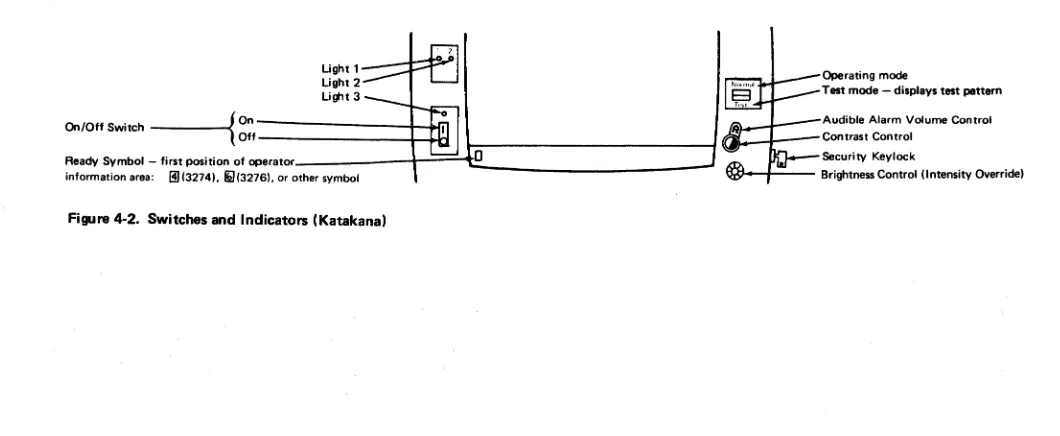
3·2 Katakana Test Patterns 3-4 3·3 Japanese (English) Test Patterns 3·5 4·' Switches and Indicators 4·'
4·2 Switches and Indicators (Katakana) 4·2 4·3 Lower Frame 4·3
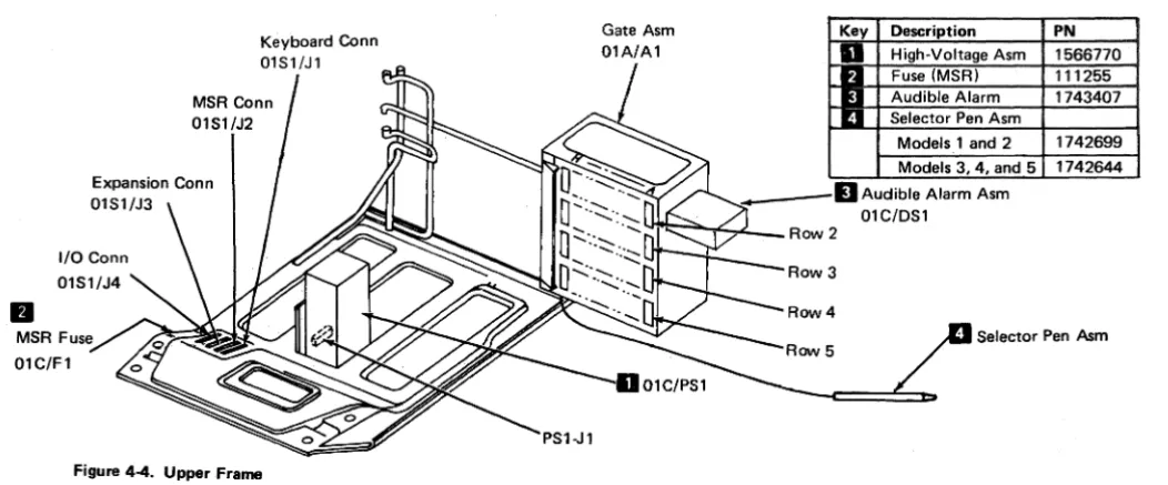
4-4 Upper Frame 4-4
4·5 CRT and CRT Frame Assembly 4·5 4·6 Card Locations, (D) Type 4-6 4·7 Card Illustrations, (D) Type 4·7 4·8 Card Locations, (M) Type 4-8
4·9 Card Illustrations, (M) Type 4·9
4·' 0 Keyboard 4·'0
4·" Fuse Locations-Low.voltage Power Supply 4·'1 4·12 Prime Power and DC Voltage Distribution 4·'2 4·13 Operator Controls 4·'3
4·14 Operator Controls and Indicators 4·14 4· 15 Feature Cabling 4·15
4·'6 Logic Gate to Keyboard Cables 4-16 4·17 DC Power Distribution 4·17
5-, CRT and High-Voltage Power Supply 5·2 5·2 Yoke Adjustments 5-2
5·3 Yoke Grounding Clips 5·2
CE SAFETY PRACTICES
All customer engineers are expected to take every safety precaution possible and to observe the following safety practices while maintaining IBM equipment:
1. You should not work alone under hazardous conditions or around equipment with dangerous voltage. Always advise your manager if you MUST work alone. 2. Remove all power, ac and dc, when removing or
assem-bling major components, working in the immediate area of power supplies, performing mechanical inspection of power supplies, and installing changes in machine circuitry.
3. The wall box power switch, when turned off, should be locked or tagged in the off position. Affix "Do not Operate" tags, form 229-1266, when applicable. Pull the power supply cord whenever possible.
4. When it is absolutely necessary to work on equipment having exposed operating mechanical parts or exposed live electrical circuitry anywhere in the machine, the following precautions must be followed:
a. Another person familiar with power-off controls must be in the immediate vicinity.
b. Rings, wrist watches, chains, bracelets, and metal cuff links shall not be worn.
c. Only insulated pliers and screwdrivers shall be used. d. Keep one hand in your pocket.
e. When using test instruments be certain that controls are set correctly and that proper-i:apacity insulated probes are used.
f. Avoid contacting ground potential (metal floor strips, machine frames, etc. - use suitable rubber mats purchased locally if necessary l.
5. Safety glasses must be worn when:
a. Using a hammer to drive pins, riveting, staking, etc. b. Power hand drilling, reaming, grinding, etc. c. Using spring hooks, attaching springs. d. Soldering, wire cutting, removing steel bands_ e. Parts cleaning, using solvents, sprays, cleaners,
chemicals, etc.
f. Working under other conditions that may be hazardous to your eyes. REMEMBER, THEY ARE YOUR EYES.
6. Special safety instructions, such as handling cathode-ray tubes and extremely high voltages, must be followed as outlined in CEMs and Safety Section of the Maintenance Manuals.
7. Do not use solvents, chemicals, greases, or oils that have not been approved by IBM.
a.
Avoid using test equipment or tools that have not been approved by IBM.9. Replace worn or broken tools and test equipment. 10. The maximum load to be lifted is that which in your
opinion and management's does not jeopardize
your own health or well-being or that of other employees.
11. All safety devices such as guards, shields, signs, and ground wires shall be restored after maintenance.
12. Each customer engineer is responsible for being sure that no action on his part renders a product unsafe or exposes customer personnel to hazards.
J _ J 13. Place removed machine covers in a safe out<>f-the-way
place where no one can trip over them.
14. All machine covers must be in place before the machine is returned to the customer.
15. Always place the CE tool kit away from walk areas, where no one can trip over it (for example, under a desk or a table).
16. Avoid touching mechanical moving parts (when lubri-cating, checking for play, etc.!'
17. When using a stroboscope do not touch ANYTHING -it may be moving.
18. Avoid wearing loose clothing that may be caught in machinery. Shirt sleeves must be left buttoned or rolled above the elbow.
<---, 19. Ties must be tucked in the shirt or fastened to it with a tie clasp (preferably nonconductive) approximately 3 inches from the end. Tie chains are not recommended. 20. Before starting equipment, make certain that fellow CEs
and customer personnel are not in a hazardous position. 21. Maintain good housekeeping in area of machines while
performing and after completing maintenance. Artificial Respiration GENERAL CONSIDERATIONS 1. Start Immediately. Seconds Count
Do not move victim unless absolutely necessary to remove from danger. Do not wait or look for help or stop to loosen clothing, warm the victim, or apply stimulants. 2. Check Mouth for Obstructions
Remove foreign objects - Pull tongue forward. 3. Loosen Clothing - Keep Warm
Take care of these items after victim is breath ing by himself or when help is available.
4. Remain in Position
After victim revives, be ready to resume respiration if necessary.
5. Call a Doctor
Have someone summon medical aid. 6. Don't Give Up
Continue without interruption until victim is breathing without help or is certain Iy dead.
Rescue Breathing for Adults Victim on His Back Immediately 1. Clear throat of water i food, or foreign matter.
, - 2. Tilt head back to open air passage.
3. Uft jaw up to keep tongue out of air passage. 4. Pinch nostrils to prevent air leakage when you blow. 5. Blow until you see chest rise.
6. Remove your lips and allow lungs to empty. 7. Usten for snoring and gurglings, signs of throat
obstruction.
8. Repeat mouth·to·mouth breathings 10·20 times a minute. Continue rescue breathing until victim breathes for himself.
~
~inalmouth'
W{"
~ o-mouth.. position
Thumb and
.---=-finger positions
Reprint Courtesy Mine SafQ-ty Appliances Co.
Safety Notices
I
I
I
I
I
DANGER: All power unit removal and replacement procedures must be performed with power turned off and with the power cord disconnected. DANGER: All persons touching a CRT or near a
CRT that is not protected must have eye and arm protection.
DANGER: High voltage can be present when Indicator 2 is off.
DANGER: Safety glasses must be worn when the machines are being worked on with the power on and the covers off.
DANGER: Voltages are present in the heat sinks on the analog card when the power is on. Also, be careful when removing this card because the heat sinks will be hot (at high temperatures). DANGER: Ferro capacitor 01D/C1 is grounded
only when the capacitor is retained by its mounting spring.
The machine frame is grounded only when the prime power assembly 01D/A1 is mounted and fastened in place.
The ferrotransformer assembly 01D/T1 is grounded only when it is mounted and fastened in place.
Caution: The CRT weighs about 7.25 kg (16 pounds). Protect and support the CRT when removing and replacing it to prevent damage to the CRT and other units.
Caution: The 3278 must be off before cards and cables are reseated or swapped. Be careful not to loosen cards or cables when working on the 3278. This could cause intermittent failures then or at a later time.
Caution: The indicator above the ON/OFF switch is not a primary Power On indicator. Machine voltage may be present when this indicator is off.
Chapter 1. Introduction
1.1 General
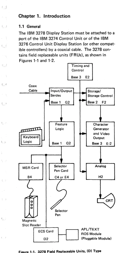
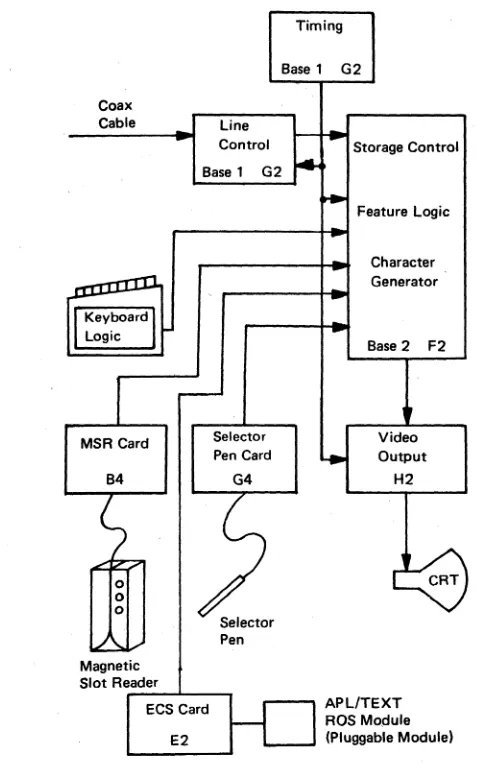
The IBM 3278 Display Station must be attached to a port of the IBM 3274 Control Unit or of the IBM 3276 Control Unit Display Station (or other compat-ible controllers) by a coaxial cable. The 3278 con-tains field replaceable units (FRUs). as shown in
Figures ,-, and '-2.
Coax
Timing and Control Base 3 E2
_ _ ..:.C..:.ab_'_e_~~lnput/OutPut
Serdes
Storagel Storage Control
MSR Card
Magnetic
Base 1 G2
Feature Logic
Base 1 G2
Selector Pen Card
Selector Pen
Slot Re_,..:a:..:d:;:.e;,..r --l _ _ ....,
ECS Card
D2
Base 2 F2
Character Generator and Video Output Base 3 E-2
Analog
H2
[image:11.288.31.276.15.548.2]APLITEXT ROS Module (Pluggable Module)
Figure 1-1. 3278 Field Replaceable Units, (D) Type
Coax Cable
MSR Card
B4
Line Control Base 1 G2
Selector Pen Card
Selector Pen Magnetic
Slot Reader
---"--
....
ECS Card E2
Timing
Base 1 G2
Storage Control
Feature Logic
Character Generator
Base 2 F2
Video Output
H2
[image:12.288.34.273.41.424.2]APL/TEXT ROS Module (Pluggable Module)
Figure 1-2. 3278 Field Replaceable Units, (M) Type
.J
[-_,I
There are two configurations of the logic for the 3278 Display Station. The first is the (D) type, shown in Figures 1-1,4-6, and 4-7. Three base logic cards are used in this configuration: base 1 (G21, base 2 (F21, and base 3 (E2). The second configuration, the (M) type, shown in Figures 1-2,4-8, and 4-9, has two base cards: base 1 (G2) and base 2 (F2). Note the new locations of the feature cards when present with the second configuration.
The 3278 Display Station Model 5 has the (M) config-uration only, and can display either an 80- or a 132-character line. The offline test describes the method for testing and aligning the Model 5.
The (D) type basic logic is packaged on three cards, one 2WX3H and two 4WX3H, and contains basic functions as follows:
Base card 1 - 01A/A 1 G02
Interface to coax, command decode and gates, and paths to features.
Base card 2 - 01A/A 1 F02
Storage, counters, and storage control. Base card 3 - 01A/A1E02
Character generator, dot character line and row counters, video serializer, and control.
The (M) type base logic is packaged on two cards, one 2WX3H and the other 4WX3H. Most of the basic functions are contained in the 4W card, which is located at 01 A/A 1 F2. The interface to the coax cable, the dot counter, and the video serializer are located on the card in 01A/A1G2.
1.1.1 Electrical Grounding
The 3278 is electrically connected between ac and dc returns at the unit. A ground wire is attached from the upper chassis to the gate and then to dc return at card location 01A/A 1 H2P8.
The coax return (shield) is isolated from the dc return at the 3278. With the ac power cord disconnected, a correctly wired unit should indicate continuity
between ac and dc ground, and an open circuit between the customer coax shield and the 3278 dc ground.
Major frame static points exist around the CRT area of the machine. Poor or no contact at these points may cause intermittent or erratic display operation such as:
• No display (blank screen)
• Erratic raster on the lower or the upper half of the screen
• A bright miniature raster in the center of the screen
• The high-voltage power supply cycling on and off • A single line on the top of the screen
If the initial MAP procedures do not isolate the erratic display problem, check the following static ground points before retrying the MAPs.
• CRT harness (see Figure 4-5)
• Yoke shield and CRT connector (see Figure 5-') • Yoke/centering rings (see Figure 5-3)
• Contrast/intensity cOntrol (see Figure 4-5) • Yoke grounding clips (see Figure 5-3)
The brightness-contrast assembly is grounded through a spring clip located behind the brightness assembly. Verify this connection by removing the brightness knob and checking for continuity between the frame and the brightness potentiometer shaft. (See Figure 4-5.)
Failure to maintain good grounding connections at all ground locations may cause erratic POR reset operation.
1.1.2 Equipment Lightning Protection
The 3278 is designed to provide a low-impedance energy path from the external coax shield to frame (ac) ground for potentials above 36 V. Additional information on lightning protection for the customer coax (customer responsibility) is provided in the IBM 3270 Information Display System: Installation Manual-Physical Planning, GA27 -2787.
1.2 Maintenance Plan
The maintenance plan for the 3278 uses the following: • Operation tests to sense failures, both for problem
determination and for verification.
• FRU swapping as an aid to failure isolation. • Maintenance analysis procedures (MAPs) to give
a planned procedure to isolate and repair any failure on the 3278.
1.3 Operation Tests
Operation tests include offline and online tests. • Offline tests (Test mode) - The 3278 offline tests
are activated by placing the Normal/Test switch in the Test position, taking the 3278 offline from its control unit, and putting it in Test mode. • Online tests- The 3278 online tests are in the
control unit to which the 3278 is attached. Online tests may be requested from any online display station with a keyboard, and may be run on any specified online terminal attached to the same control unit. The results of the test are displayed at the requesting display station. Online tests include a routine to display the error log for any terminal attached to the same control unit, and for the control unit.
Operation tests are described in detail in Chapter 3.
1.4 FRU Swapping
The FRU swapping procedures are given in the MAPs in Chapter 2; FRU locations and part numbers, in Chapter 4.
1.5 MAPs
The MAPs are designed to give a quick and effective procedure for isolating and repairing any problem on the 3278. To use the MAPs effectively, you must observe the following rules:
1. Before the 3278 MAPs are used, the customer should have performed problem determination, using the 3278 Problem Determination Guide (PDG), located under the keyboard hand rest.
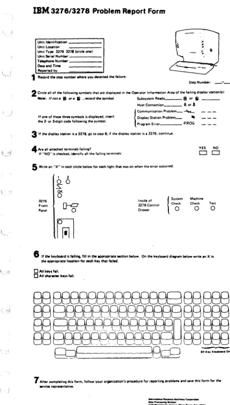
2. If a failure was sensed while the 3278 PDG was being used, the failing step number was record-ed on a problem report form [GX23-0201, or GX18-1033 for Japanese (English) or Katakana]; see Figure 1-3. This step number will be useful when the MAPs are being used. 3. If the failure is intermittent, cards and cable
connectors should be checked for correct seating, and voltages should be checked for correct tolerances as described in MAP 01. Check the tightness of the screws on the capa-citors in the low-voltage power supply. 4. The 3278 should be online to its control unit
unless the MAP instructs you to place the 3278 offline. If the 3278 is offline (in Test model. some of the symptoms may differ from those for which the MAPs were designed. 5. The MAPs will.instruct you to reseat/swap
cards in a spl'icific sequence. The first card is the first probable cause of the failure, the next card is the next probable cause, etc.
6. Always reseat the cards and their associated cables, and test before swapping parts. Reseat the cables, and check the capacitor screws for tightness before swapping the low-voltage power supply.
7. When the analog card (card 01A-H2) is swapped, the new card may need adjustment.
8. Always reinstall the original part when the new part did not repair the problem. 9. If you go through the MAP once without
repairing the problem, go back to the starting point and go through the MAP a second time. If, after a second pass through the MAPs, the trouble is not repaired, call for assistance. 10. The ECS card 01
AI
A1D02 (D) or 01A/A 1 E2(M) may contain a pluggable APL/TEXT char-acter generator ROS module. Static discharge can damage the ROS module if you do not follow proper grol,lnding procedures when handling a loose module, that is, one not in-stalled in a card socket. Hand contact should first be made to the foam or wrapping in which
IBM
3276/3276 Problem Report FormUnitldentif,catiOfi
Ul'litLoatlon
Un.tTyp' 3276 32711circleoont)
UI'IItStri.1
NUmber:::::::=
TItIpIIoneNumblr-D.t,andTinw
Rtportedby
1 Reeord tile U~ number wh'~ you det&eted the flilur.,
~
a ;
_ .~ .. G
" ,
-St~N\,I1'TIbef 2 Circle ill 01 It. follow,"" symbols Ihilt are dlsplilYld In the Operator Information Aru of 1M tailing display tUitlon!I):
No.: Ifnor. BI or. 5 .rtJCOrdth.symboi. SubivstemRudy _ _ BI or lJ _ _
Ifoneolth •• thl'",ymbol,isdispl.yed"nwt tfI.2-or3-dlg,tcod. followlMg the symbol.
Host Connection _ _ A or 1
{ C,mm,"''''"'" P',""m_ ---... Di\.PIilyStal,onProblem...-- ...
Prog',m Erro. _ _ _ PROG 3 'fthtdispllYsW,on il' 3278,!I"oto niP 6: il the d1lpllY Stll,on ,s.3276 ,continue.
4
Are ,II .ttached lerm,nlls f.ilmg~ If"NO"is<;he(:ked,ident,fvalithefailin9term'n .. l~YES NO
D O
5
Write an "X" in each eirel. below 'or each hght thIN WilS on when the error occurred.1 2
0 0
.s-OK
0 { S,,,.m MilChm~
3276 Ins,deof
FrOM
D-i?
3276 Control Ct>eck Check Te.tPanel Drawer 0 0 0
~
6
II the keyboard il I.iling, fill in the ~opr"te lK'lion below. On me keybo¥eI elillgO',," below write an X inthe~opriatlfOCltlonfor"d1keythltf.iled.
DAilkeyllail. DAllchlrKtltrkeylfail.
888888888888888~88888
88 888888B888888888 888
88
~88R8P8PB8888n
88 EBB
BB
B8BBPPOBBPR8B~
88888
Q:dE
\8cO
.,.~._.o""7 After compl.t!ng thil form. follow your organilltion', procedure lor rtpOrting problems ,nd uv. this form IOf In.
.l"IiOlrepresentlt'~ •.
"'*'-co_'~i .. I"'"for""oL8MCO' _ _ ion.
Depoot .... nI&3T. NligIoborhoodROIid. Ki .... lOn.N_York 12401 (lCopynilM Inll1'n.UO..-Su$, ... MacfI'I>e$COOVOr.'''''' 1918. 1979
_ _ _ _ ~_c _ _
----
"QW_._. _ _ ._~1_~.::::;;..
_._"
... ...::::..-::: :':...co.;:;:.. _...
_'_
•. u.I ... [image:17.288.32.267.38.451.2]... , ... ~
..
__
_ _ . _ ... _ . I U U.I"''''Figure 1-3. IBM 3276/3278 Problem Report Form
the module is packed. Also, while holding a module to be installed in a socket, first make hand contact to the socket pins to drain off any static charge.
11. Terminals that have the ECS feature, card loca-tion 01A/A1D02 (D), will have the selector pen card in location 01A/A1E4. All references to the selector pen card for the (D) type will be location 01A/A1C04 or 01A/A1E4.
Caution: The 3278 must be off before you reseat or swap cards and cables. Be careful not to loosen cards or cables when working on the 3278. This could cause intermittent failures then or at a later time.
Chapter 2. MAPs
MAP 00, Start/Restart MAP
Start here to isolate any failure on the 3278 Display Station.
Note: The two different logic types used in the 3278 are indicated by 1M) and (0): (M) indicates the logic using two base cards (Figures 1·2 and 4·8); (0) indio cates the logic using three base cards (Figures 1·1 and 4·6). Throughout the MAPs an (M) or a (0) will follow the card callouts to indicate in which logic the problem card is located. Where neither (M) nor (0) is indlcated, the card is the same for both logic types.
001
(Entry Point A)
Is this the first time through this MAP ?
(Highly intermittent or not failing now; take NO leg.)
Y N
2 A
Use the Error log and Error Code to FRU list (par. 3.3.2.3); use the Symptom/Repair list to aid you in developing your action plan. A few examples are:
1. Swap suspected FRU; for example, if 3276 log shows 41 and 77 errors, swap A·G2 for isolation.
2. Request a Retain Data Bank/EWS Search (based on logged error codes, gathered data, and your observation of the problem). 3. Check voltages for proper levels and/or
ripple. (See Figure 4·11; all voltages are
± 10%.) See par. 5.4 for 44 V adjustment. 4. Check the ferrocapacitor for proper opera·
tion by doing the following: a. Switch off the unit.
b. Discharge the capacitor by performing steps 1, 2, and 3, from par. 6.2.2. Note: Exchange the capacitor if it is distorted from internal pressure. c. Set the CE meter to the R x 1 K scale.
A
1
002
d. Touch the test leads of the CE meter across the capacitor terminal~; the meter should momentarily deflect. Reverse the meter test leads; the meter should deflect again. If there is no meter deflection, exchange the ferrocapacitor.
5. Check coax connectors and electrical grounding as described in par. 1.1.1. 6. Contact FSC/Branch Support for assistance.
Is one or more light-emitting diode (LED) "off" (3 LEOs to left of screen)?
Y N
005
003
Is card kit or FRUs available for swapping?
Y N
I
Go to MAP 01-001 Entry Point A. 004Use SymptomlRepair List or go to MAP 01-001 Entry Point A as experience dictates.
Go to MAP 01-001 Entry Poi nt A.
'.J
SYMPTOM/REPAIR LIST
Symptom Action
•
Reseat/swap cards called out in this column.•
Swap/adjust card A 1 H2 where called out.•
All logic cards are in the 01 A gate.:._1 1. Display blank Hold the intensity control fully
(no cursor, clockwise (Test position), and divider line, or check for symptoms a, b, c, and light on screen):
##.
" ,q a. Normal raster (0) A1E2 or raster on A1F2 upper or
lower half of screen
b. Single line or A1G2 glow at top (0) A1E2 of screen A1F2
~-'--- A1H2
c. No raster Check fuse 1 on the low-voltage power supply. Swap the high-voltage power supply.
A1H2
Swap/adjust the CRT yoke. 2. Display dim at Check analog card adjustment
_ ~~J maximum (raster blanking).
intensity, or
raster visible at A1H2 minimum
; [,-J intensity. Check intensity potentiometer
and cables. (See Figure 4-13.) 3. Displays single A1H2
line at top or A1F2
" .J center of screen, Swap/adjust the CRT yoke. or data only on
bottom half of screen.
4. Displays widely (0) A1E2 spaced diagonal A1F2 lines or is out of A1H2 sync (moving or
vibrating screen).
Symptom Action 5. Displays full (01 A1E2
raster with A1H2 intensity set to A1F2 normal (cursor
may also displayl; or each character position displays the full character space.
6. Displays one of A1F2 the following: A1G2
•
Divider Line only•
Divider Line and a line at bottom of screen•
Random data after power on•
Test pattern when online7. Cursor flashes at A1G2 random locations. A1F2
8. Display size Reseat!swap the high-voltage changes when power supply. (See par. 6.2.5.1 intensity is
changed.
9. Display tilted or Adjust the yoke or analog card incorrect size. potentiometers. (See par. 5.1.1 10. Cursor missing, Verify with the Normal/Test
will not blink or switch in the Test position. reverse. Check the analog card adjust·
ment (see Chapter 51. A1F2 (01 A1E2 A1G2
11. Normal/Test A1G2 switch operation A1H2
failure. Check the switch and cables. (See Figure 4.13.1
12. Monocase (01 A1E2
(A,a/AI A1G2
switch operation Check the switch and cables. failure. (See Figure 4.13.1
" ... "1
Symptom Action
"!--;:c" 13. Incorrect A1G2
characters A1F2 display and
Device Check is indicated (Machine Check =X 77).
14. Incorrect (01 A1E2
'~'--::~ characters A1G2
display with- A1F2 out Device
Check; or
't:::~ extra or
miss-ing dots on screen.
If in APL/TEXT Reseat/swap ROS module in mode only 01A!A1D2 (0)
or 01 A/A1 E2 (M)
(0) A1D2 or
1M) A1E2 15. Test Mode 1 A1G2 characters (0) A1E2 incorrect on A1F2 half or all of
the screen, or in incorrect sequence.
16. Will not change A1F2 row length A1H2 (Model 5 only).
17. Keyboard not (0) A1G2 working, input 1M) A1F2
inhibit not Set the Normal/Test switch to indicated. the Test position, and try to Characters do enter from the keyboard. If you not enter. cannot enter, swap the keyboard
logic card. Verify keyboard cables (Figure 4-16l. 18. One keyboard Set the Normal/Test switch to
key fails. the Test position, and check the code for the failing key. (See par. 3.3.1.2,-Test Mode 2.1 If the character is incorrect, swap the keyboard logic card. (See Chapter 6.1 If the character is correct, check the keyboard I D jumpers. (See Figure 4-10.1 If the jumpers are correct, swap
Symptom Action
the keyboard logic card.
19. Incorrect (0) A1G2 characters (M) A1F2
enter from Reseat/swap the keyboard logic keyboard. card. Check the keyboardlPC
mounting screws. Check the keyboard cables. (See Figure 4-16.)
20. 3278 cannot be Check:
logged online.
•
Run L Test 0 (AAIO) to enable•
Security Key on (clockwise)•
Normal/Test switch in Normal position • Coaxial cable connectorseated A1G2 A1F2
(0) A1E2
Go to Entry Point A, MAP 05. 21. Selector-pen (0) A1C4
failures. (0) A1E4
(M) A1G4
Reseat/swap the selector pen. A1G2
A1F2 22. MSR failures. A1B4 A1G2 Reseat/swap the MSR. 23. Error Codes See par. 3.3.2.3, Error Log/
Indicated. Repair Action. 24. APL/TEXT (0) A1D02
mode errors. A1G02 (M) A1E2
MAP 01
Terminal Failure MAP
PAGE 1 OF 13
ENTRY POINTS
FROM
ENTER THIS MAP
MAP
ENTRY PAGE
STEP
NUMBER
POINT NUMBER NUMBER
00
A
001
EXIT POINTS
EXIT THIS MAP
TO
PAGE
STEP
MAP
ENTRY
NUMBER NUMBER
NUMBER POINT
2
007
00
A
3
011
02
A
2
010
g~
A
2
009
A
2
008
05
A
3
012
05
A
001
NOTE: If the 01A/A1H2 card is exchanged the adjustments must be verified. It is possible for an adjustment to be in a position that may appear to be a failure. Test mode 1 can be used to verify that the 01 A/ A 1 H2 card is correctly adjusted for width, height and raster blanking. See Adj. Section 5.2.
(Entry Point A)
Is one or more light emitting diodes (lights 1,2 and 3) 'OFF' or very dim?
N 002
Is there an error code displayed for this failure? (See 3.3.2.3 for applicable codes)
If
332
ABC
C
1
MAP 01Terminal Failure MAP
PAGE 2 OF 13
003
(A normal display is - cursor, divider line, indicators and/or system written data as expected.)
Is there an INCORRECT display?
3
D
N
004
Is this a Keyboard failure? (Exercise keyboard in test mode, use Y path if results are unexpected)
N
005
Is this a Feature failure? (Does not include keyboard)
N
006
Is this a subsystem indicated failure (error code displayed or failures not detected by off line tests 1, Z or 3.)?
N
007
Use test mode procedure (section 3.3.1), to identify problem.
Go To Map 00, Entry Point A.
008
Go To Map 05, Entry Point A.
009
Go To Map 04, Entry Point A.
010
Go To Map 03, Entry Point A.
A B D
1
l'
2
MAP 01Terminal Failure MAP
PAGE 3 OF 13
011
Go To Map 02, Entry Point A.
012
Go To Map 05. Entry Point A.
013
Is light 3 above power ON/OFF switch on? (If very dim use N path.) See Fig 4-1, 2 for location)
N 014
Verify that the power on switch is on, line power cable plugged in an active outlet and seated at the primary power box.
Are above conditions correct?
r
~!~.ct
and verify. 016Switch unit off.
Verify Fuse F1 in main power box (Figure 4-3). Did fuse fail?
N
017
Verify low voltage supply fuses (F2. F3. F5, FS).
(See fuse locator Figure 4-11). Are all fuses good?
1 1
1 054
E F G H
H
3
I
MAP 01
Terminal Failure MAP
PAGE 4 OF 13
018
Exchange failing fuse or fuses. Switch Unit On. (Wait 30 sec.) Did fuse or fuses fail again 1
N
019
Verify correct operation.
If problem occurs again start o~er at Entry Point A of this MAP to identify new symptom.
020
Switch unit off.
Remove 01A/A1H2 card and exchange fuse(s). Switch Unit On.
Did fuse(s) fail again 1 N
021
Switch unit off.
Exchange 01A/A1H2 card and adjust.
If fuse fails after new 01
AI
A 1 H2 card is installed problem can be in high voltage power supply or yoke.Remove connector on high voltage power supply and yoke to isolate.
022
Switch unit off.
Short is in Low voltage power cable logic cards or keyboard. Reinstall 01
AI
A 1 H2 removed in step 20.Remove logic cards and keyboard cable. Exchange failing fuse and switch unit on. Did fuse fail again 1
If
5 5
J
K
G J K
344
MAP 01
023
Terminal Failure MAP
PAGE 5 OF 13
Exchange logic cards one at a time in the following sequence; 01A/A1G2, F2, E2 (0), or 01A/A1F2, G2 (M).
Switch unit off and ON for each exchange. (Permit 30 sec. for power to be on each time).
If fuse does fail after a card is reinstalled, exchange that card with a new card and start over.
If fuse does not fail when all the logic cards are reinstalled, reconnect keyboard cable. If reinstalling the keyboard cable causes the fuse to fail exchange the keyboard logic card. Should exchanging of the keyboard card not repair the problem the keyboard should be exchanged.
024
Repair or exchange the Low Voltage cable. See Figure 4-12 for wiring figure.
025
Remove Line Power cable from power outlet. Switch Unit On switch to ON and measure resistance across pins of line power cable plug. (This is a continuity test of the line power cable, main power box, power switch, ferro primary and fuse F1 in the main power box, normal is less than 5 ohms.)
Measures 5 ohms or more 7
9 6
L M
MAP 01
I
Terminal Failure MAP
PAGE 6 OF 13
026
Plug line power cable in and switch unit on.
[image:30.288.45.263.37.452.2]Verify voltage at J4 on the low voltage power supply between pins 1 and 4 for 48 volts AC. (See Figure 4-11 ).
Is the voltage correct?
1
:27
Reverify power source outlet. If outlet is good, exchange ferro.028
Verify DC voltages:
(DC Common is at C3 - (minus) on low voltage power supply
(Voltages are ± 10% except +8)(See Figure 4-11)
+5
at fuse F6.
+8.5 at fuse F3.
+44 at fuse F5.
-5
at 010/PS1-J3-3.
-12 across Cl (F2).
-44 at 010/PS1-J3-1.
+8V+/-lvolt 010/PSI-J2-2,
(derived from +8.5V supply).
Are all voltages correct? N
029
Switch unit off. Remove analog card. Switch unit on.
Verify voltages as shown in preceding step. Is one or more voltages incorrect?
[[
977
N P
Q
MAP 01
Terminal Failure MAP
PAGE 7 OF 13
030
Switch power off.
Exchange analog card 01 A/ A 1 H2. Switch unit on.
Adjust as required (see 5.2). Test for proper operation.
031
Is the -44 volts incorrect?
N
032
Switch unit off.
Disconnect keyboard cable at 01 A/A 1 G5 (D) or 01A/A1F5 (M).
Switch power on. Verify failing voltage.
Is voltage still incorrect?
N
033
Replace keyboard logic card and/or keyboard cable/cables as required.
Reinsert analog card in 01 A/ A 1 H2. Switch power on.
Test for proper operation. Return to customer.
034
Switch power off. Remove all logic cards. Switch unit on.
Is voltage still incorrect?
888
R S T
R S T
777
MAP 01
I
Terminal Failure MAP
PAGE 8 OF 13035
Switch unit off.
Reinsert logic cards one at a time to isolate failing card.
038
Switch unit off.
Exchange low voltage power supply.
Reinsert logic cards. keyboard cable and analog card.
Switch power on. Test for proper operation.
037
Switch power off.
Remove mask assembly (see 6.5).
Disconnect 01C/A1P1 from 01C/A1J1 (See Fig. 4-5).
Switch unit on.
Verify -44 volts at 01D/PS1-J3-1. Is voltage still incorrect?
N
038
Exchange Intensity/Contrast Control (see 6.5.3). Reinsert analog card. 01 C / A 1 P1 and mask assembly.
Switch power on. Test for proper operation.
039
Verify seating of connectors on low voltage power supply. If all connectors are seated but problem is still present exchange Low Voltage power supply. Switch Unit On and test for proper operation.
L N
5 6
MAP 01Terminal Failure MAP
PAGE 9 OF 13
040
Verify seating of the power distribution cable at the low voltage power supply (P2 and P3) and at the logic gate. If reseating the connectors does ,': not correct the problem, verify the DC voltages
at the logic gate. See Figure 4-12.
Exchange the 01
AI
A 1 H2 card, adjust and test for proper operation.041
Remove line power cable from main power box(P1).
Verify resistance from pin B to pin C of line power cable socket (J1) (See Figure 4-12).
Measures 5 ohms or more "1
1
:2
Exchange line power cable and test for correct operation.043
Remove plug P3 from J3 on main power box. Verify resistance from pin 1 to pin 3 on P3 (Ferro Primary verify).
Measures 5 ohms or more"1 N
044
Remove Plug P2 from J2 on main power box. Test for 1 ohm or less between pins 2 and 3 then between pins 1 and 4 on P2. (Test of main power switch). (See Figure 4-12)
Measures t ohm or less for both tests "1
If
111
000
U V W
F U
v
W
3 9 9 9
045
MAP 01
Terminal Failure MAP
PAGE 10 OF 13
Exchange ON/OFF switch. Reinsert previously removed plugs. Reconnect in terminal and test for proper operation.
046
Exchange prime power asm. (Figure. 4-3). Test for proper operation.
047
Exchange Ferro Transformer. Verify correct operation.
048
Exchange fuse F1 in main power box. Switch Unit On and wait up to 30 sec. Did fuse fail again 7
l
:a
Verify correct operation.050
Switch unit off.
Remove plug P3 from J3 on main power box. Exchange fuse.
Switch Unit On. Did fuse fail again 7
1 1
1 1
X
y
E X Y
3 1 1
a a
MAP 01
Terminal Failure MAP
PAGE 11 OF 13
051
Switch unit off.
Reconnect P3 to J3 on main power box. Remove plugs from J 1 and J4 on low voltage power supply. (See Figure 4-11)
Switch Unit On.
Did fuse F1 fail again?
I
:52
Exchange low voltage power supply. Verify correct operation.
053
Exchange ferro transformer. Verify correct operation.
054
Exchange main power box.
Reconnect and verify correct operation.
055
Is light 1 (Sweep Indicator) (LED#1) ON? (Use N path if very dim)
1
2
Z
N056
Switch unit off.
Exchange the 01
AI
A 1 H2 card.Switch Unit On, adjust and verify correct operation.
Z
1
1
I
MAP 01
Terminal Failure MAP
PAGE 12 OF 13
057
Is light 2 (High Voltage Indicator) ON. or very dim?
See Fig 4-1. 2 for location).
DANGER
High Voltage can be present when the High Voltage Indicator is OFF
N
058
Switch unit off.
Exchange the High Voltage power supply. Switch Unit On and verify correct operation. Is light 2 ON?
N
059
Switch unit off.
Exchange and adjust the 01
AI
A 1 H2 card. Verify correct operation.If the problem remains, exchange low voltage power supply, yoke.
060
Verify correct operation.
061
Is light 2 very dim?
1
3
A
A
N
062
Start over at MAP 00 Entry Point A if first time through MAP.
A
A
1
2
063
MAP 01
Terminal Failure MAP
PAGE 13 OF 13
Exchange and adjust card 01 AI A 1 H2. Verify correct operation.
MAP 02
Display MAP
PAGE 1 OF 19
ENTRY POINTS
FROM
ENTER THIS MAP
MAP
ENTRY PAGE
NUMBER
POINT NUMBER
02
A
1
02
B
5
02
c
11
02
0
15
EXIT POINTS
EX IT TH I S MAP
TO
PAGE
STEP
MAP
NUMBER NUMBER
NUMBER
1
002
01
18
108
8l
1
004
19
113
05
001
(Entry Point A)
STEP
NUMBER
001
028
066
088
ENTRY
POINT
A
A
A
A
Are all three lights (#1, 2 and 3. See Fig 4-1 for location) on7
1
:2
Go To Map 01, Entry Point A.003
Remove feature cards if present. Is problem still present7
N 004
Go To Map 04, Entry Point A.
MAP 02
Display MAP
I
PAGE 2 OF 19 005Disconnect coax signal cable at 01S1/J4 (Figure 4-4). Set TEST/NORMAL switch to TEST then to NORMAL.
Is there a normal Cursor or normal divider line displayed on the screen? (Use N path if no display or raster on screen or flashing on and off or erratic.)
N
006
Is there a normal divider line on the screen?
1
:7
Go to Page 5, Step 028, Entry Point B. 008Is there a normal cursor on the screen?
1
; ..
PagoI1 ... _ ...c.
010
Is the screen blank? (No light) (Use N path if flashing or erratic.)
N
011
Does the intensity control affect the light on the screen?
9 5 3 3
BCD E
o
E
2 2
012
MAP 02
Display MAP
PAGE 3 OF 19
Exchange and adjust the 01 AlA 1 H2 card. Is the problem still present?
N
013
Reconnect coax signal cable, feature card(s). Verify correct operation.
Identify new problem if present.
014
Verify the following:
1. Cable and connectors from analog card to CRT base socket (Figure 4-14).
2. Cable and connectors from analog card to intensity control potentiometer (Figure 4-13). 3. Intensity control potentiometer.
4. Intensity override switch (Spring loaded). 5. Possible short circuited CRT
6. Reconnect coax signal cable, feature card(s).
015
Is the display on the screen normal? (Good characters, in focus and normal size. Use intensity override if necessary to determine size and condition of raster)
N
016
Is display size or focus a problem? (Use N path if raster problem)
4 4
F G
N 017
Go to Page 5, Step 028, Entry Point S.
F G
3 3
MAP 02I
Display MAPI
PAGE 4 OF 19018
Use analog adjustment procedure to verify correct adjustment of 01 AI A 1 H2 card and focus of high voltage power supply.
Is problem still there after verifying analog adjustments? (Chapter 5.2)
I
:19
Reconnect coax signal cable, feature card(s). Verify correct operation.
020
Exchange and adjust 01 AI A 1 H2 card. Problem still there?
I
:21
Reconnect coax signal cable, feature card(s). Test for proper operation.
022
Exchange High Voltage power supply. Reconnect coax signal cable, feature card(s). Verify correct operation.
023
Is the display flashing on and off?
5
H
N
024
Exchange the 01A/A1H2, E2, F2, G2 (0), or
01 AI A 1 H2, F2, G2 (M) cards one at a time. Reconnect coax signal cable, feature card(s). Verify correct operation.
C H
2 4
025
MAP 02
Display MAP
PAGE 5 OF 19
Hold intensity control in override position. Does raster flash off and on?
N
026
Exchange cards 01AI A1 F2, 01AI A1 E2 (D), or 01 AlA 1 G2, F2 (M).
Reconnect coax signal cable, feature card(s). Test for proper operation.
027
Exchange High Voltage power supply.
I i Reconnect coax signal cable, feature card(s). Verify correct operation.
028
(Entry Point B)
Use the intensity override control to force a display on the screen.
Does the screen have a raster displayed with override ON?
N
029
Is the screen blank? N
030
Exchange logic card 01 AI A 1 E2 (0), or 01A/A1F2 (M).
Is problem still present?
8 6 6 6
J
K L M
K L M
555
031
MAP 02
Display MAP
PAGE 6 OF 19
Reconnect coax signal cable. feature card(s). Test for proper operation.
032
Exchange and adjust 01
AI
A 1 H2 card. Reconnect coax signal cable. feature card(s). Test for proper operation.·033
Exchange and adjust the 01 AI A 1 H2 card. Is problem still present7
034
I
NReconnect coax signal cable. feature card(s). Test for proper operation.
035
Observe the neck of the CRT to see if a light from the filament is visible. (Remove cone shield on neck of CRT if necessary. Chapter 5.1.1)
Is there a light? N
036
Switch unit off.
Verify fuse F1 on low voltage power supply. Is fuse good7
N
031
Exchange fuse (1A 58) and switch unit on. Did fuse fail again7 (permit 30 sec.)
1I
887 7
N P
Q
R
:" 038
MAP 02
Display MAP
PAGE 7 OF 19
Reconnect coax signal cable, feature card(s). Verify correct operation.
039
Switch unit off.
Remove socket from CRT. Exchange fuse.
Switch Unit On.
Does fuse fail again 7
N 040
Exchange CRT. Do alignment procedure, Reconnect coax signal cable, feature card(s). Verify correct operation.
041
Test for short in cable from Low Voltage power supply to CRT socket (Remove plug J2 from Low Voltage power supply and test for short between pins 1 and 14 at the CRT socket). Repair or exchange as needed.
Reconnect coax signal cable, feature card(s). Verify correct operation.
J
N P
566
MAP 02Display MAP
PAGE 8 OF 19
042
Remove and verify the connections at the CRT socket.
Measure resistance on pins 1 and 14 at CRT base.
If more than 5 ohms exchange CRT.
If less than 5 ohms verify cable and connections from Low Voltage power supply to CRT socket. (See Figure 4-14.
Test for an open wire from J2-3 to CRT socket pin 1 and for an open between J2-9 to CRT socket pin 14. (Figure 4-12)
Repair or exchange cable if open. If cable tests good exchange the CRT. Reconnect coax signal cable, feature card(s). Verify correct· operation.
043
Exchange the High Voltage power supply. Reconnect coax signal cable, feature card(s). Verify correct operation.
044
Does raster appear normal? (Covers full display area)
N 045
Is there a single line at or near the top of the screen?
999
STU
B STU
2 888
MAP 02
Display MAP
PAGE 9 OF 19
046
(Raster abnormal and/or on lower part of screen only.)
Exchange one at a time, card 01 A/ A 1 E2, G2, F2, H2 (0), or 01A/ A1 F2, G2, H2 (M). Reconnect coax signal cable, feature card(s).
Verify correct operation.
047
Exchange 01 A/ A 1 H2, F2, E2 (0), or 01A/A1H2, G2, F2 (M) card.
Reconnect coax signal cable, feature card(s). Verify correct operation.
048
Exchange 01A/ A 1 G2, F2 card (0) or 01 A/ A 1 F2, G2 (M).
Is problem still present7
I
N049
Reconnect coax signal cable, feature card(s). Verify correct operation.
050
Exchange the 01 A/ A 1 H2 card and adjust. Reconnect coax signal cable, feature card(s). Verify correct operation.
051
Is there a cursor on the screen 7
N
052
Go to Page 11, Step 066, Entry Point C.
1
o
V
V
9
I
MAP 02
Display MAP
PAGE 10 OF 19
053
Is there a divider line on the screen 7
I
:54
Go to Page
5.
Step 028. Entry Point B.055
Is the divider line near the bottom of the screen 7
I
:56
Go to Page 5. Step 028. Entry Point B.
057
Verify position of the security key for ON (Full clockwise) if feature is installed.
Was the security key in the correct position 7 (If the security key is not installed use the V path.)
1
1
W
N058
Switch key to ON (Full clockwise). Has the problem been corrected7
N
059
Verify wIring to the security key and key switch.
Repair or exchange (See Figure 4-14). Reconnect coax signal cable. feature card{s). Verify correct operation.
060
Reconnect coax signal cable, feature card{s). End of call.
W
1
o
I
MAP 02
Display MAP
PAGE 11 OF 19
061
Does the cursor appear normal? N
062
Is there a divider line near the bottom of the screen?
N
063
Exchange 01 A/ A 1 G2 card.
Reconnect coax signal cable, feature card(s). Test for proper operation.
Problem still present?
I
~Of~1I
065
Exchange 01 A/A 1 H2 card and adjust. Test for proper operation.
066
(Entry Point C)
Put the Test/Normal switch in the Test position. Is the test pattern displayed and does the cursor appear to be a bar under the first character at top left of the screen?
1 1 1
332
X
yZ
Z
1
1
I
MAP 02
Display MAP
PAGE 12 OF 19
087
Press 'Reset' key one time. (Test Mode 3). Press 'K' key.
Press ': key.
Is there a reverse flashing cursor on screen?
the
1
~
A
N068
Is the test pattern correct except for cursor? N
069
Is the display correctly adjusted? N
070
Use adjustment procedure for 01 A/ A 1 H2 card and yoke. (Chapter 5.2).
Reconnect coax signal cable, feature card{s).
Verify correct operation.
071
Exchange 01A/A1F2, E2, or G2 (OJ, or 01A/A1F2, G2 card (M).
Reconnect coax signal cable, feature card{s). Verify correct operation.
072
Exchange 01A/A1G2, F2 (OJ, or 01A/A1G2, F2 card (M).
Reconnect coax signal cable, feature card{s). Verify correct operation.
x
Y A
1 1 A
111
MAP 02
Display MAP
PAGE 13 OF 19
2
073
Exchange 01
AI
A 1 G2, F2, or E2 card (D), or01A/A1G2, F2 card (M).
Reconnect coax signal cable, feature card(s}. Verify correct operation.
074
The cursor was inhibited or placed off the screen by the controller. Verify controller failure by swapping coax cables with another terminal to ensure that the problem follows.
075
Is the cursor and divider line the only display on the screen?
N
076
Is the Test Pattern displayed? N
077
Exchange cards 01
AI
A 1 G2, F2, E2 (0), or01A/A1G2, F2 (M) one at a time to isolate bad card.
Reconnect coax signal cable, feature card(s). Verify correct operation.
078
Go to Page 15, Step 088, Entry Point D.
079
Does the display alignment and focus appear correct? (Position, size). Use test mode 1 to
'c.r verify.
If
1 1
4 4
A A
"l
B C
A A
B C
1 1
3 3
MAP 02
Display MAP
PAGE 14 OF 19
I
080
Use the adjustment procedure to correct alignment or focus of the display. If the problem cannot be corrected by adjustment exchange the 01
AI
A 1 H2 card, high voltage power supply.Reconnect coax signal cable, feature card(s). Verify correct operation.
081
Does the intensity and contrast control work correctly?
1
5
A
o
N
082
Exchange 01
AI
A 1 H2, 01AI
A 1 F2 card. Has the problem been corrected?N
083
Use Figure 4-13 to isolate problem to the cable, connector or intensity
I
contrast assembly.Repair or exchange.
Reconnect coax signal cable, feature card(s). Verify correct operation.
084
Adjust 01
AI
A 1 H2 card.Reconnect coax Signal cable, feature card(s). Verify correct operation.
A
D
1
4
MAP 02
Display MAP
PAGE 15 OF 19
'" 085
Does the Test/Normal switch cause the Test Pattern to be displayed when in Test position only?
c,«i N 086
Exchange cards 01 A/ A 1 G2, 01 A/A 1 F2, 01A/A1E2 (Dl. or 01A/A1G2, F2 (M).
Is problem still present?
I
:87
Reconnect coax signal cable, feature card(s). Verify correct operation.
088
(Entry Point D)
See Figure 4-13 to verify switch and cable to logic.
Repair or exchange.
Reconnect coax signal cable, feature card(s). Verify correct operation.
089
Put the Test/Normal switch in Test position. Is test pattern 1 correct? (See 3.3.1).
N
090
Is there a cursor, divider line or any characters on the screen?
1 1 1
866
A A A
<'¥i
E F G
A A
F G
1 1
5 5
I
091
MAP 02
Display MAP
PAGE 16 OF 19
Exchange 01A/A1G2 (0), or 01A/A1F2, G2 card (M).
Reconnect coax signal cable, feature card(s). Verify correct operation.
092
Are displayed characters readable but some/all missing or wrong?
N
093
Exchange 01 A/ A 1 G2 (0), or 01 A/ A 1 G2, F2 card (M).
Reconnect coax signal cable, feature card(s). Verify .correct operation.
Problem corrected?
r
I
;'h,ng, 01A/A1H2
""nI.
Verify correct operation.
095 End of call.
096
Verify dual case/mono case switch is in Aa position.
Are both upper and lower case characters displayed?
1 1
7 7
A A
H
J
A A
H
J
1 1
6 6
097
MAP 02
Display MAP
PAGE 17 OF 19
Switch unit off.
Measure resistance from 01 A/ A 1 E2J 13 to JOB (0) or 01A/A1F2G13 (M) to
Ja.
Is resistance less than 5 ohms 7 N
098
Use Figure 4-13 to isolate open in switch or cable to O1A/A1H2G13.
Repair or exchange.
Reconnect coax signal cable, feature card(s). Verify correct operation.
099
Exchange 01 A/A 1 G2 card.
Reconnect coax signal cable, feature card(s).
I ~ Verify correct operation.
Problem still present7
r
I
:00
End of Call.
101
Exchange 01A/A1E2 (0), or 01A/A1F2 (M). Verify correct operation.
102
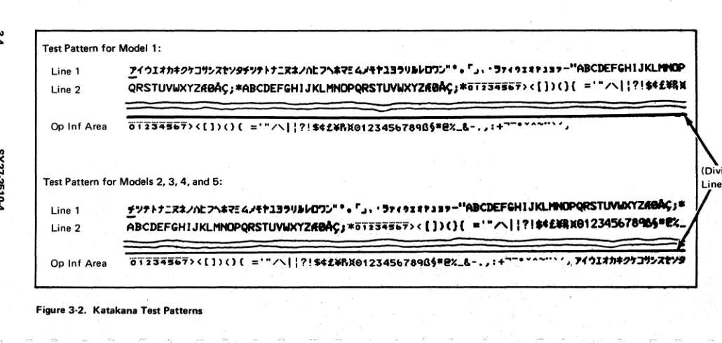
Are the characters displayed in the correct sequence7 (See Figure 3-1.3-2,3-3)
1 1
~ ~
K L
A A A
MAP 02
Display MAP
PAGE 18 OF 19
~ ~ ~
577
103
Remove feature cards if present. Is the problem still present?
N
104
If only one feature card is installed. exchange with another card and test for correct operation. If more than one feature card is present. isolate to one card by exchanging one card at a time.
Reconnect coax signal cable. feature card(s).
Verify correct operation.
105
Exchange 01A/A1F2. 01A/A1G2. 01A/A1E2 (0). or 01A/A1F2. G2 (M).
Reconnect coax signal cable. feature card(s). Verify correct operation.
106
Exchange 01 A/ A 1 F2. 01 A/ A 1 E2 card (0). or 01A/A1F2. G2 (M).
Reconnect coax Signal cable. feature card(s). Verify correct operation.
107
Is keyboard exercise of test mode 2 correct? N
108
Go To Map 03. Entry Point A.
1
9
A
M
t _)
A
M
1
8
109
MAP 02
Display MAP
PAGE 19 OF 19
(Display is not recognized to be ON LINE to the controller).
Verify that the controller is operational.
Is the controller communicating with other terminals?
I
~10
Use controller Maintenance Information Manual to locate cause of problem.
111
Put test/normal switch in normal position.
Exchange 01A/A1G2, 01A/A1F2, 01A/A1E2 (D), or 01A/A1G2, F2 cards (M).
Reconnect coax signal cable, feature card(s). Is problem still present?
f
~:~fy
oooect ope,ation.113
Go To Map 05, Entry Point A.
,1 ~I
MAP 03
Keyboard MAP
PAGE 1 OF 4
-.~ ENTRY POINTS
FROM
ENTER THIS MAP
1",;1 ,
MAP
ENTRY PAGE
STEP
NUMBER
POINT NUMBER NUMBER
01
A
001
05
A
001
001
(Entry Point A)
(,>! Is this a mechanical failure? (Key binds, broken,
worn or clicker sound failing)
N
002
Use Test Mode 2 to verify failing key or keys. Is there more than one key failing?
N 003
Does any character enter from the failing key?
N
004
Does the cursor move, advance, in test mode when the key is pressed?
3 2 2 2
ABC D
N
005
Exchange the module for the failing key. (See Keyboard section 6.7). Verify repair by using Test Mode 2.
006
MAP 03
Keyboard MAP
PAGE 2 OF 4
Verify seating of keyboard cable connector to the terminal.
Verify internal keyboard cable connector to logic gate (See Figure 4-16).
If problem is not corrected by reseating of cable connectors, exchange the keyboard logic card.
Verify the keyboard 1.0. jumpers to be sure that the new logic card is the same.
(If exchange of the keyboard logic card does not correct the problem, use the keyboard cable chart to trace cable wires, connector pins to isolate a failing cable or connector.) Verify using Test Mode.
007
Verify seating of keyboard cable connector to the terminal.
Verify internal keyboard cable connector to iogic gate. (See Figure 4-16)
If problem is not corrected by reseating of cable connectors, exchange the keyboard logic card. Verify the keyboard 1.0. jumpers to be sure that the new logic card is the same.
(If exchange of the keyboard logic card does not correct the problem, use the keyboard cable chart to trace cable wires, connector pins to isolate a failing cable or connector.)
Verify using Test Mode.
008
Verify seating of keyboard cable connector to the terminal.
Is problem still present?
H
3 3
E F
A E F
122
MAP 03Keyboard MAP
PAGE 3 OF 4
009
V~rity correct operation.
010
Exchange 01 A/ A 1 G2 then E2 card (D), or 01A/A1G2 then F2 (M).
Is problem still present7
r
~!:""
correct ope<at;on.012
Verity internal keyboard cable connector to logic gate. (See Figure 4-16)
If problem is not corrected by reseating of cable connectors, exchange the keyboard logic card. Insert the keyboard 1.0. jumpers ensuring that the new logic card is jumpered the same as the card exchanged.
(If exchange of the keyboard logic card does not correct the problem, -lise the keyboard cable chart to trace cable wires, connector pins to isolate a failing cable or connector.)
Verity using Test Mode.
013
Is this a clicker failure 7 N
014
Exchange the failing part by using the Keyboard repair section.
4
G
015
MAP 03
Keyboard MAP
PAGE 4 OF 4
Put the Test/Normal switch in Test position. Clicker should. sound for each key depression. Does the clicker sound?
N
016
Exchange logic card 01 A/ A 1 G2 (0), or 01A/A1F2 (M).
Is trouble still present?
r
I
;17
End of call.
018
Exchange the clicker. (See keyboard Repair. Section for exchangement. See Chapter 6-7). Verify correct operation.
Does clicker sound?
r
;!~hang.
the
keybo"dlog~
",ro.020
End of call.021
Clicker has been disabled by the system.
l:4
t...r
, ~ ""-~
t
_~4-'-~
MAP 04
Feature Error MAP
PAGE 1 OF 11
ENTRY POINTS
FROM
ENTER THIS MAP
MAP
ENTRY PAGE
STEP
NUMBER
POINT NUMBER NUMBER
01
A
001001
(Entry Point A)
Does this terminal contain one or more feature cards?
N
002
Exchange 01 AI A 1 G2 (0), or 01 AlA 1 G2, F2 (M). Reconnect coax signal cable.
Verify correct operation.
003
Is this a failure of only one feature1 (Use N path if don't know)
N
004
Remove all feature cards but one. Is the problem still present1
332
ABC
005
MAP 04
Feature Error
MAP
PAGE 2 OF 11
(Entry Point EI
Reinstall each of the previously removed feature cards one at a time unti" the problem occurs again. Did the selector pen feature card cause the problem?
N
006
Did the MSR feature card cause the problem?
N 007
Did the ECS/TEXT feature