Dynamic Video Content Streaming
Adnan Shaout
UM-Dearborn-USA
Samir A. El-Seoud
British University in
Egypt
Islam Taj-Eddin
British University in
Egypt
Kamel
H.Shafa’amri
PSUT - Jordan
ABSTRACT
Streaming video applications on the Internet generally have very high bandwidth requirements and yet are often unresponsive to network congestion. In order to avoid congestion collapse and improve video quality, these applications need to respond to congestion in the network by deploying mechanisms to reduce their bandwidth requirements under conditions of heavy load. Unfortunately current video applications scale to fit the available bandwidth without regard to the video content. In this paper a dynamic content-aware scaling mechanism will be presented that reduces the bandwidth occupied by an application. This has been achieved by dropping frames (temporal scaling) and by reducing the quality of the frames transmitted (quality scaling). Based on internet connection speed of the client, a streaming video client and server that is capable of scaling MPEG stream using temporal and quality scaling have been designed.
Keywords
Moving Picture Experts Group (MPEG), Video streaming, Video frame, Network congestion, Transmission Control Protocol (TCP), User Datagram Protocol (UDP), Peak Signal to Noise Ratio (PSNR), Spectral redundancy.
1. INTRODUCTION
The Internet disseminates enormous amounts of information for a wide variety of applications all over the world. About 77% of the data bytes accessed by the Web are in the form of multimedia objects like images [11], audio and video. Furthermore, about 33% of these multimedia objects are streaming media that can potentially benefit from the proposed scaling technique. These data exchanges can result, in periods of transient, congestion on the network.
The simultaneous transmission of very large volumes of data at high transmission rates tends to enhance the likelihood of network congestion [1].
In times of network congestion, the random dropping of packets by the router may seriously degrade multimedia quality, since the multimedia streams generally bring in numerous dependencies between packets of different frames. For example, dropping a given frame will cause the following dependent frames to be useless since they cannot be displayed. It would be better to drop independent frames rather than leaving them occupying unnecessary bandwidth.
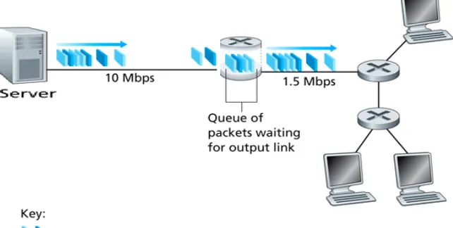
[image:1.595.157.478.532.694.2]Figure 1 shows the effect of network congestion. When the queue is full of packets (network congestion), the router will drop randomly some packets, rather than waiting indefinitely or occupying unnecessary bandwidth. That action may affects the quality of the video.
To overcome network congestion, various control strategies have been built into the Transmission Control Protocol (TCP) and the User Datagram Protocol (UDP).
TCP treats network congestion through the use of throttle senders, by reducing the number of packets that the sender can send. Many multimedia applications, such as internet phone and video conferencing, often do not run over TCP for this reason. These applications do not want their transmission rate throttled, even if the network is very congested. Also, unlike traditional data flows, multimedia flows do not necessarily require a completely reliable transport protocol like TCP by retransmitting dropped frames. This is done because the multimedia can absorb a limited amount of loss and still achieve acceptable quality. Note that retransmitting dropped packets is inefficient and will cause delay. Retransmission can be fine for all types of networks, but it is not appropriate for some multimedia applications with which only small end-to-end delay is acceptable [1].
User Datagram Protocol (UDP) is one of the core members of the Internet Protocol Suite, the set of network protocols used for the Internet. UDP is generally used for multimedia flows over TCP. With UDP, computer applications can send messages, in this case referred to as "datagrams", to other hosts on an Internet Protocol (IP) network without requiring prior communications to set up special transmission channels or data paths. UDP uses a simple transmission model without implicit handshaking dialogues for providing reliability, ordering, or data integrity. Thus, UDP provides an unreliable service and datagrams may arrive out of order, appear duplicated, or go missing without notice. UDP assumes that error checking and correction is either not necessary or performed in the application, avoiding the overhead of such processing at the network interface level. UDP is a data networking protocol which has been incorporated under the architecture of the widely-used Transmission Control Protocol/Internet Protocol (TCP/IP). This protocol defines a robust way to transmit real-time data bits (like voice and video) from one place to another in the form of individual datagrams (i.e. a data packet which has no acknowledgment features associated with it). UDP offers only a minimal transport service, non-guaranteed datagram delivery, and gives applications direct access to the datagram service of the IP layer. UDP is used by applications that do not require the level of service of TCP or that wish to use communications services (e.g., multicast or broadcast delivery) not available from TCP. UDP is almost a null protocol; the only services it provides over IP are checksumming of data and multiplexing by port number. Therefore, an application program running over UDP must deal directly with end-to-end communication problems that a connection-oriented protocol would have handled (e.g., retransmission for reliable delivery, packetization and reassembly, flow control, congestion avoidance, etc.), when these are required. The fairly complex coupling between IP and TCP will be mirrored in the coupling between UDP and many applications using UDP. UDP does not have a congestion control mechanism built in, and therefore most multimedia flows are unable to respond to network congestion and adversely affect the performance of the network [1].
In [6] authors build a scheduling mechanism that favors transmission of more important frames at the expense of the less important ones. They validate their approach by means of test-bed experiments and demonstrate a significant improvement of the end video quality.
In [6] as the upstream capacity of most peers is restricted, webcasting high bandwidth content is a continuing problem with traditional application-level multicasting techniques. Split and Merge Multicast provides a solution to this problem. The authors present the results of a large scale field trial of the technology
In [15] authors present a receiver-based, bandwidth estimation rate control mechanism with content-aware probability retransmission to limit the burden on multimedia transmission congested network.
In [9] with the features of MPEG compressed video stream, authors present a new method for extracting key frames. An improved histogram matching method is used for video segmentation; followed by the extraction of the key frames in order to utilizing the features of I-frame, P-frame and B-frame for each sub-lens. MPEG Stream will be introduced at the next section.
The contribution in this paper is to develop a system that uses media scaling techniques by dropping video frames (temporal scaling) and reducing quality of the video frames (quality scaling) depending on the client internet connection speed. The system will drop the least important frames of the video (B-frames), which will reduce the number of sending frames and reduces the probability of dropping important frames by the network router when the network is congested. The proposed system is flexible (if there is no network congestion the video will be displayed in full quality. If network is congested the video will be encoded based on the network bandwidth feedback), and avoid network congestion effects (frames will not be dropped randomly by the router). In case of high bandwidth the delay will be minimal.
2. PRELIMINARIES
While the terms "frame" and "picture" are often used interchangeably, strictly speaking, the term picture is a more general notion, as a picture can be either a frame or a field. A frame is a complete image captured during a known time interval, and a field is the set of odd-numbered or even-numbered scanning lines composing a partial image. When video is sent in interlaced-scan format, each frame is sent as the field of odd-numbered lines followed by the field of even-numbered lines [14].
2.1 Streaming Video
Streaming video is a sequence of "moving images" that are sent in compressed form over the Internet and displayed by the viewer as they arrive. Streaming media is streaming video with sound. With streaming video or streaming media, a Web user does not have to wait to download a large file before seeing the video or hearing the sound. Instead, the media is sent in a continuous stream and is played as it arrives. The user needs a "player", which is a special program that uncompress data and sends video data to the display and audio data to the speaker. A player can be either an integral part of a browser or downloaded from the software maker's Web site [8][12].
In the field of video compression a video frame is compressed using different algorithms with different advantages and disadvantages, centered mainly around on amount of data compression. These different algorithms for video frames are called picture types or frame types. The three major picture types used in the different video algorithms are I, P and B. They are different in the following characteristics [13][14]:
I-frames contain the most amount of bits and therefore take up more space on the storage medium.
P-frames can use data from previous frames to decompress and are more compressible than I-frames.
B-frames can use both previous and forward frames for data reference to get the highest amount of data compression.
2.2 MPEG Stream
Moving Picture Experts Group (MPEG) was formed by the International Organization for Standardization (ISO) to set standards for audio and video compression and transmission [8].
MPEG algorithms compress data to form small bits that can be easily transmitted and then decompressed. MPEG achieves its high compression rate by storing only the changes from one frame to another, instead of each entire frame. The video information is then encoded using a technique called Discrete Cosine Transform (DCT). MPEG uses a type of lossy compression, since some data is removed. But the diminishment of data is generally imperceptible to the human eye. MPEG generally produces better-quality video than competing formats, such as Video for Windows, Indeo and QuickTime
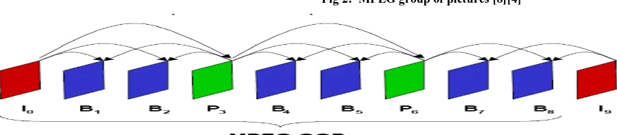
A typical MPEG stream contains three types of frames as seen in figure 2 (group of pictures (GOP)):
I-frame is an 'Intra-coded picture', in effect a fully specified picture, like a conventional static image file. P-frames and B-frames hold only part of the image information, so they need less space to store than an I-frame, and thus improve video compression rates. It is ideal when the image changes allot, but take up a lot of bits. So if too many I-pictures have been used, an overall higher bit rate to keep the quality up is needed [14].
2.2.1
I-picture/I-frame (intra coded picture)
Frames can be grouped into sequences called a group of pictures (GOP). A GOP is an encoding of a sequence of frames that contain all the information that can be completely decoded within that GOP. For all frames within a GOP that reference other frames (such as B-frames and B-frames), the B-frames so referenced (I-B-frames and P-frames) are also included within that same GOP. Each GOP begins with this type of picture. Although the compression of I-frame only is very fast, it has the drawback of producing a very large file sizes. The produced file is larger by the factor of 3 (or more) than original encoded MPEG-1 video, depending on how temporally complex that video is. I-frame only MPEG-1 video is very similar to MJPEG video. So much so that very high-speed and theoretically lossless (in reality, there are rounding errors) conversion can be made from one
format to the other, provided a couple of restrictions (color space and quantization matrix) are followed in the creation of the bit stream [4].
2.2.2
P-picture/P-frame
(predictive
coded
picture)
P-frame ('Predicted picture') holds only the changes in the image from the previous frame. For example, in a scene where a car moves across a stationary background, only the car's movements need to be encoded. The encoder does not need to store the unchanging background pixels in the P-frame, thus saving space. P-frames are also known as delta-frames. It takes up much less bits than I-pictures. Using P-pictures lets you keep an overall lower bit rate, and use the excess to improve the I-pictures. However, P-pictures may decrease the image quality if there are too many changes from the previous frame. The option to detect scene changes in an encoder will automatically insert an I-picture if it detects a big change between two frames. P-frames exist to improve compression by exploiting the temporal (over time) redundancy in a video. P-frames store only the difference in image from the frame (either an I-frame or P-frame) immediately preceding it (this reference frame is also called the anchor frame) [14].
2.2.3
B-picture/B-frame (bidirectional
pre-dictive coded picture)
B-frame ('Bi-predictive picture') saves even more space by using differences between the current frame and both the preceding and following frames to specify its content. It is based on past and future I and P-pictures. They provide the best compression but, as with P-pictures, have problems when the image changes too much. Also, bear in mind that B-pictures cannot be based on other B-pictures, so don't use too many in a row or the image quality may suffer, especially if there are any cuts or sudden changes. If you're using a high average bit rate (above 6500), you can use I and P-pictures only. B-frames can also be beneficial in videos where the background behind an object is being revealed over several frames, or in fading transitions, such as scene changes [14].
[image:3.595.104.552.623.721.2]Fig 3: Temporal media scaling [11]
2.3 Quantization of Digital Data
Quantization, in mathematics and digital signal processing, is the process of mapping a large set of input values to a smaller set. Quantization of digital data is the process of reducing the accuracy of a signal, by dividing it into some larger step size (i.e. finding the nearest multiple, and discarding the remainder/modulu). The frame-level quantizer is a number from 0 to 31 (although encoders will usually omit/disable some of the extreme values) which determines how much information will be removed from a given frame. The frame-level quantizer is either dynamically selected by the encoder to maintain a certain user-specified bitrate, or (much less commonly) directly specified by the user. Quantization eliminates a large amount of data, and is the main lossy processing step in MEPG-1 video encoding. This is also the primary source of most MPEG-1 video compression artifacts [2]. In the next section, we will discuss the effect of changing the quantization levels on the resulting frames.
2.4 Media Scaling
There are two types of media scaling currently used:
2.4.1 Temporal scaling
In Temporal Scaling the application drops frames. The order in which the frames are dropped depends upon the relative importance of the different frame types. In the case of MPEG, the encoding of the I-frames is done independent of other frames and they are therefore the most important and are dropped last. The encoding of the P-frames is dependent on the I-frames and the encoding of the
B-frames is dependent on both the I-frames and the P-frames. The B-frames are the least important frames since no frames are encoded based upon them. Therefore, B-frames are most likely to be the first ones to be dropped [11]. Figure 3 shows an example of a temporal scaling.
2.4.2
Quality scaling
In quality scaling, the quantization levels are changed, chrominance is dropped or compression coefficients are dropped. The resulting frames are lower in quality and may have fewer colors and details [11].
To reduce the bandwidth of the video when the network is congested the video with high motion will look better if all the frames are kept, but the frames will have low quality. On the other hand, video with low motion will look better if some frames are dropped, and the remaining frames will have high quality.
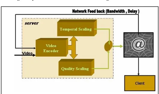
[image:4.595.87.523.596.724.2]Figure 4 shows adaptive content aware scaling system architecture. Depending upon the amount of motion the server invokes one appropriate filter to reduce the bandwidth occupied by the stream (i.e. quality filter for a high motion scenes and the temporal filter for a slow motion scene). There may be a larger benefit to perceptual quality with hybrid scaling (i.e. combining temporal scaling with quality scaling) [11].
3. THE PROPOSED NEW MEDIA SCALING
SYSTEM
In order to successfully develop a system that makes scaling decisions based upon the rate of the network bandwidth and delay , we needed to develop a system take the bandwidth and delay of the network and then integrate this with the MPEG encode. The whole system would then be capable of making content-aware decisions for the choice of the scaling mechanism to use for a particular sequence of frames.
The system consists of 4 distinct modules: server, MPEG encoder, network feedback generator and the client.
Server: The server in the system takes as input an MPEG file, parses and packet size it and stream it over the network to the client. The server is also capable of quantifying the bandwidth and delay of the network using the network feedback.
MPEG encoder: The encoder scales the video using temporal scaling or quality scaling or both.
Network feedback: The return to the server a feedback (Bandwidth, Delay) of the network.
Client: The client module is a regular MPEG decoder that is capable of playing out frames that are received over network sockets.
The functional requirements of the new media scaling system are as follow, see figure 5:
1. When the user at the client side wishes to play a video, client sends a request to the server.
2. The server will receiving the request and the network feedback, prepare the requested video frames and passes them to the encoder.
Depending on the network feedback the encoder will decide the type of scaling. At the case of network with a low bandwidth, all video frames are kept but with low quality (quality scaling).
3. At the case of network with high delay, video transmission will be better if some frames are dropped, but the remaining frames will have high quality (Temporal scaling).
[image:5.595.317.582.92.248.2]4. The server sends the encoded video to the client.
Fig 5: Dynamic Video Content Streaming.
4. SYSTEM IMPLEMENTATION
4.1 First Set of Tests
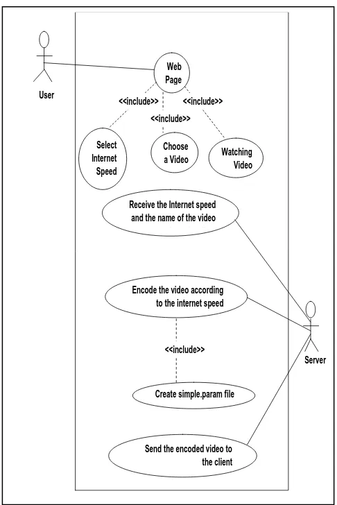
For the sake of testing, the functional requirements of the new media scaling system are as follow, see figure 6:
1. When the user at the client side wishes to play a video, the client must choose his internet connection speed and then choose the video that he wants to watch.
2. The server will receive both the request and the internet connection speed of the client.
3. Depending on the internet connection speed the server will encode the video frames using MPEG encoder by dropping B-frames (temporal scaling) and reducing the quality of the video frames (quality scaling).
4. To encode the video frames, the server will create a file called (simple.param). This file contains the location of video frames in the server, the number of B-frames and the quantization level of the I-frame, P-frame and B-frame. The encoder then will read this file and encode the video frames. 5. The number of B-frames and the quantization level
depend on the internet connection speed as shown in table 1.
6. The server sends the encoded video to the client. 7. The client side will watch the video after certain
Web Page
Watching Video Choose
a Video Select
Internet Speed
Receive the Internet speed and the name of the video from the client
Encode the video according to the internet speed
Create simple.param file
Send the encoded video to the client <<include>>
<<include>> <<include>>
<<include>> User
Server
Fig 6: The Use Case tool [7] design for the testing of the proposed new media scaling system.
Table 1: Internet connection speed and MPEG scaling techniques.
The php, JavaScript language, HTML language, apache server, Linux OS, and MPEG-1 [12] encoder were used to implement the proposed system design and algorithm.
The proposed system is consist of a client and server simulator with the server capable of scaling MPEG stream using temporal and quality scaling based on the internet connection speed of the client. Table 1 was used to determine the number of B-frames and the quantization level depend on the internet connection speed.
[image:6.595.59.302.77.441.2]Five test cases were applied to the new media System as shown at table 2. The waiting time is the time the client should wait from the request to watch the video until the beginning of watching the video.
Table 2: Five test cases results
4.2 Second Set of Tests
[image:6.595.348.552.96.184.2]In another set of tests, the quality of scaling will be changed according to the bandwidth values, when the value of the quality scale increase, the quality of the video decrease, see table 3. According to the delays values the temporal scaling values had been set, see table 4.
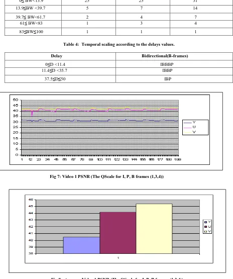
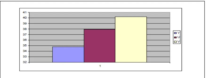
The PSNR for the original video and various encoded videos had been measured. The relation between PSNR (Y, U, and V Components), at the Y axis, and the Frame Number, at the X axis, appears in Fig 7 and Fig 9. The average PSNR (Y, U, and V Components) of Fig 7 appears in Fig 8. The average PSNR (Y, U, and V Components) of Fig 9 appears in Fig 10.
Spectral redundancy (i.e. the redundancy between each color component) can be removed with various color conversions (YUV, YIO, HIS) [3]. At (YUV), Y stands for the luma component (the brightness), U and V are the chrominance (color) components. PSNR (Peak Signal to Noise Ratio) is one of the widespread objective metrics to assess the application level Quality of video transmissions [10][15]. PSNR, measured in dB (i.e. the decibel), measures the error between a reconstructed image and the original one. dB is a measure of the ratio between two quantities, for the paper's case it will be signal-to-noise ratio. The PSNR signal-to- noise ratio of the video is inverse relation, the larger the PSNR value, the better the video quality perceived by the end user.
Internet connection speed (used at the proposed design)
# of B-frames I-QScale P-QScale B-QScale Video quality
128 Kbps IBP 25 25 31 Very low
256 Kbps IBBP 20 20 26 Low
512 Kbps IBBBP 15 15 21 Medium
1024 Kbps IBBBBP 10 10 10 High
2048 Kbps IBBBBBBP 1 1 1 Very high
Internet connection speed
Waiting time
128 Kbps 17 seconds
256 Kbps 14 seconds
512 Kbps 12 seconds
1024 Kbps 10 seconds
Table 3: Quality Scaling according to the bandwidth values.
Bandwidth (BW) I-QScale P-QScale B-QScale
0≤ BW<13.9 25 25 31
13.9≤BW <39.7 5 7 14
39.7≤ BW<61.7 2 4 7
61≤ BW<83 1 3 4
[image:7.595.70.526.91.183.2]83≤BW≤100 1 1 1
Table 4: Temporal scaling according to the delays values.
Delay Bidirectional(B-frames)
0≤D <11.4 IBBBP
11.4≤D <35.7 IBBP
[image:7.595.61.525.112.667.2]37.5≤D≤50 IBP
Fig 7: Video 1 PSNR (The QScale for I, P, B frames (1,3,4))
[image:7.595.58.525.208.451.2]Fig 9: Video 2 PSNR (The QScale for I, P, B frames (2,4,7))
Fig 10: Average Video 2 PSNR (The QScale for I, P, B frames (2,4,7))
5. CONCLUSION AND FUTURE WORK
Based on the internet connection speed of the client, a streaming video client and server that is capable of scaling MPEG stream using temporal and quality scaling was designed and tested. The developed system will drop the least important frames of the video (B-frames), to reduce the number of sending frames and to reduce the probability of dropping important frames by the network router when the network is congested.
A possible future goal is to enhance, explore and exploit the proposed system in wireless video streaming. The success of the proposed system with congested networks and the need for streaming videos over the wireless [10][5] are encouraging us to take that step at the future.
6. REFERENCES
[1] Chung J. and Claypool M., May 2000, Better-Behaved, Better-Performing Multimedia Networking. In Proceedings of SCS Euromedia Conference (COMTEC).
[2] Citizendium, a wiki free encyclopedia project, MPEG-1 http://en.citizendium.org/wiki/MPEG-MPEG-1
[3] Hemy M., Hangartner U., Steenkiste P., and Gross T., April 1999, MPEG System Streams in Best-Effort Networks. In Proceedings of Packet Video Workshop’99.
[4] Iptv dictionary, MPEG GOP definition, http://www.iptvdictionary.com/iptv_dictionary_MPE G_GOP_definition.html
[image:8.595.52.494.291.457.2][6] Kulkarni S., 2006, Video Streaming on the Internet Using Split and Merge Multicast. Proceedings of the Sixth IEEE International Conference on Peer-to-Peer Computing (P2P'06).
[7] Laplante P.A., 2004, Real-time Systems Design and Analysis, 3rd edition. IEEE PRESS/WILEY-INTERSCIENCE.
[8] LeGall D., April 1991. Retrieved 2008-04-09, MPEG: A Video Compression Standard for Multimedia Applications. Communications of the ACM, 34(4):47–58.
[9] Liu G., Zhao J., 2010, Key Frame Extraction from MPEG Video Stream. Third IEEE International Symposium on Information Processing.
[10] Tian-Yun H., 2008, Energy-aware Multi-Path Streaming of MPEG-4 FGS Video over Wireless. The 2008 International Conference on Embedded Software and Systems Symposia - ICESS2008. (DOI 10.1109/ICESS-Symposia.2008.81).
[11] Tripathi A., May 2001, Adaptive Content-Aware Scaling for Improved Video Streaming. A Master Thesis submitted to the Faculty of the WORCESTER POLYTECHNIC INSTITUTE.
[12] University of California, Berkeley. Berkeley MPEG-1 Video Analyzer: mpeg-stat. http://bmrc.berkeley.edu/frame/research/mpeg/.
[13] Webopedia, I_frame, http://www.webopedia.com/ TERM/I/I_frame.html
[14] Wikipedia, Video compression picture types, http://en.wikipedia.org/wiki/Video_compression_pictu re_types
![Fig 4: Adaptive Content-Aware Scaling System Architecture [11].](https://thumb-us.123doks.com/thumbv2/123dok_us/8109719.790562/4.595.87.523.596.724/fig-adaptive-content-aware-scaling-architecture.webp)