Performance Analysis of Spread Spectrum with Prime
Codes in a Wireless System over a fading Channel
Sreesha S Babu
M.E-Communication Systems SNS College of Technology
Coimbatore,India
K.Jayanthi
Assossiate Professsor(ECE) SNS College of Technology
Coimbatore,India
ABSTRACT
Spread spectrum technology has become the technology for commercial systems operating in both the licensed as well as in the unlicensed spectrum. “Double-length” one hit FH pattern for dual media services provides the needs of multi users and capable of providing better services in a systems. Multiuser detectors can be employed to improve the performances. FHSS transmits the data packet on one frequency and rapidly hops to other possible frequencies to transmit the next packet. The performance of FH-SS is analyzed in AWGN channel. Prime codes are so considered as the best among the other methods. This proposes system is used to increasing the QoS, decreasing the BER and also controlling the mutual interference. The expected result shows that the performance of Prime codes over fading channels are analyses by double-length one hit FH pattern.
General Terms
FH-SS, Prime code, minimum BER.
Keywords
Frequency Hopped Spread Spectrum (FH-SS), Prime code, Galois Field, BER (Bit Error Rate).
1.
INTRODUCTION
Like wired networks, wireless communication networks also have senders and receivers of signals. However, in connection with signal propagation, these two networks exhibit considerable differences. As long as the wire is not interrupted or damaged, it typically exhibits the same characteristics at each point. Thus, one can precisely determine the behavior of a signal. The signal travels away from the sender at the speed of light. If any matter is between sender and receiver, the situation becomes more complex. The delay spread is a typical effects the multipath propagation. The effect of delay spread on the signals representing the data is a shorter impulse smeared onto a boarder impulse, or rather into several weaker impulses. Each path has a different attenuation and, thus, the received pulses have different power. Some of the received pulses will be too weak even to be detected. The energy intended for one symbol now spills over to the adjacent symbol; an effect is called intersymbol interference (ISI). The higher the symbol rate to be transmitted, the worse the effects of ISI will be, as the original symbols are moved closer and closer to each other. Due to interference, the signals of different symbols can cancel each other leading to misinterpretations at the receiver and thus causing transmission error.
Frequency-hopping is effective in combating multi-path fading because of inherent frequency diversity. Frequency-hopping spread spectrum multiple access (FH-SSMA) allows multiple users to share the same frequency band sets through
the assignment of a distinct frequency hopping (FH) pattern to different users[9]. FH sequences are used to hop the frequencies for transmission and play an important role.
For frequency hopping spread spectrum (FHSS) systems, the total bandwidth is split into many channels of smaller bandwidth plus guard spaces between the channels[13]. Transmitter and receiver stay on one of these channels for a certain time and then hop to another channel. FHSS comes in two variants, slow and fast hopping.
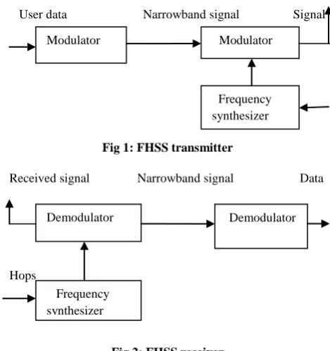
Figure 1 and Figure 2 shows the block diagram of FHSS transmitter and receiver respectively. The first step is the modulation of user data according to one of the digital-to-analog modulation schemes. This results in a narrowband signal, if FSK is used with a frequency for a binary 0 and
for a binary 1.
User data Narrowband signal Signal
[image:1.595.309.544.422.672.2]
Fig 1: FHSS transmitter
Received signal Narrowband signal Data
Hops
Fig 2: FHSS receiver
The hopping sequence is fed into a frequency synthesizer generating the carrier frequencies. A second modulation uses the modulated narrowband signal and the carrier frequency to generate a new spread signal with frequency of + for a 0 and + for a 1 respectively. Two or more transmitters may choose the same frequency for a hop, but dwell time is short for fast hopping systems and thus interference is minimal.
Modulator
Modulator
Frequency synthesizer
Demodulator Demodulator
Prime codes is defined so constructed based on the multiplication of prime finite fields (also Galois fields) GF(P) with P a prime number and “GF”Galois fields, showing ideal Hamming auto and cross correlation properties [4]. Galois field implementations are central to the design of many reliable and secure systems, with many systems implementing them in software. The two most common Galois field operations are addition and multiplication; typically, multiplication is far more expensive than addition. In software, multiplication is generally done with a look-up to a pre-computed table, limiting the size of the field and resulting in uneven performance across architectures and applications [5]. Prime codes are used in cryptography such as Diffie-Hellman protocol.
2.
MODEL DESCRIPTION
The most popular implementation of the FH spread-spectrum system is the M-ary Frequency Shift Keyed system which is also known as the conventional FH-MFSK system. The block diagram of Prime code/FHSS is Fig 3: At the FH-MFSK
transmitter, M form a message .
Message m is mapped to the transmission of a tone on sub-channel m. For the FH-MFSK system, the total duration of the
M-bit message will be referred to as the signaling-interval and will be denoted by T. The transmitter would transmit a single tone on sub-channel m for duration of T secs and the receiver would be able to decode the message reliably [12].However, in non-ideal channel conditions, the transmitter may need to employ both time and frequency diversity to increase the probability of correct reception.
Fig 3: Block diagram of Prime code / FHSS
In a frequency-hopped MFSK system each user is assigned an L- word address vector
= (1)
Where denotes user, and each word is K bits. In a transmitter, K message bits are stored in a shift register and transformed to a symbol with levels (the subscript denotes the user among M (≤ user). The data symbols with levels are encoded by an error-correcting code
signal. The address code is added to according to the rule of GF ( ) and are transformed to binary digits to produce the transmitted to binary digits to produce the transmitted
) (2)
(3)
Where and .
The transmitted signal has a form:
(t)= sin [2 t ( ] (4)
Where is the average signal power. The signal is passed to the AWGN channel. The required message is demodulated by the modulo subtraction of and address vector without loss of generality, it is assumed that user 1 is the desired user and the others are undesired ones to CCI. Moreover, it is assumed that the FH patterns of all users are known and are distinct to each other [10].
2.1 Construction of GF
(2l)
The field GF (2l) is defined by a set of 2l unique elements that is closed under both addition and multiplication, in which every non-zero element has a multiplicative inverse and every element has an additive inverse. Addition and multiplication in a Galois field are associative, distributive and commutative. The Galois field GF (2l) may be represented by the set of all polynomials of degree at most l−1, with coefficients from the binary field GF (2) the field defined over the set of elements 0 and 1[7]. Thus, the 4-bit field element a = 0111 has the polynomial representation a(x) = x2 +x+1. In contrast to finite fields defined over an integer prime, the field GF(2l) is defined over an irreducible polynomial of degree l with coefficients in GF(2). An irreducible polynomial is analogous to a prime number in that it cannot be factored into two non-trivial factors. Addition and subtraction in GF (2) is done with the bitwise XOR operator, and multiplication is the bitwise AND operator. It follows that addition and subtraction in GF (2l) are also carried out using the bitwise XOR operator, while multiplication turns out to be more complicated. In order to multiply two elements a(x), b(x) for GF (2l), we perform polynomial multiplication of a(x)·b(x) and reduce the product modulo an l-degree irreducible polynomial over GF(2). Division among field elements is computed in a similar fashion using polynomial division.
The order of a non-zero field element ord(α) is the smallest positive i such that αi = 1. If the order of an element GF (2l) is 2l −1, then α is primitive. In this case, α generates GF (2l), i.e all non-zero elements of GF(2l) are powers of α.
2.2 Construction of Dual-length Prime code
The double-weight prime codes consists of
,two-dimension pattern with code weight ,comprising rows and columns where , is the number of different weights. The number of coincidences for all cyclic-shifted versions of any two same-length or different length patterns is at most one [ ]. Also, given of double-length one-hit FH patterns starts with the Galois fields and GF(P2) of prime number and such that In regard to frequency assignment to the prime hopping patterns, it is subdividing the time period of the short patterns into equal time slot and the time period of the long patterns into slots, as
.
The 2-tuple representation is as follows:
(5) Thus, it is not necessary to use another requirement in order to optimize code performance, based on an assumption that the number of available carriers is the same as the code weight.
Source Prime code
encoder
FHSS Modulator
Channel
FHSS demodulator
Prime code decoder
2.3 Calculations in Finite Fields
Addition in GF(q) is chosen on a basis:
(x1aa+…+xrar)+(y1a1+...+yrar) = (x1+y1)a1+…+(xr+yr)ar
in other words, by adding “coordinate-wise”.
On the other hand, multiplication is chosen in a primitive root g:
(gi) .(gj) = gi+j; (6) Where the exponent is reduced mod q-1 if necessary.
In order to be able to perform both operations, it needs a table telling how to translate between the two representations. This is essentially a table of logarithms, since if = x, let it be i as the “logarithm” of x.
For the field GF (9) which is constructed by using an element a satisfying = 2 (over the integers mod 3), to find that g =1+a is a primitive element, and the table of logarithms is as follows:
= 0 = a+1
= 2a = 2a+1 = 2
= 2a+2 = a
= a+2
For example, (a+2) (2a+2) = g7. g5 = g12 = g4 = 2.
2.4 Increasing the Spectral Efficiency
The two-level FH scheme, the cross-correlation values of the modulation codes impose additional interference. Assume that one-hit FH patterns of dimension are used and the transmission band is divided into frequencies, in which 𝑀𝑚 frequencies are used to carry the modulation codes of weight 𝑤𝑚. The probability that a frequency of an interferer hits with one of the 𝑤𝑚 frequencies of the desired user is given by
/ (6)
The single-user spectral efficiency is
[Bits/sec/Hz] (7)
This implies that for a given bandwidth W, a certain data rate Rb, and a fixed number of bits, then the time-diversity factor ˜L is also fixed. Therefore, in the FH Multilevel-FSK system, we cannot use a higher ˜L to compensate for a poor channel. This limits the flexibility of the system. Another impairment associated with FH Multilevel-FSK is that of delay-spread. Consequently, the sub-channels may no longer be mutually orthogonal and energy spillovers may occur among adjacent sub-channels causing Inter Channel Interference (ICI). To avoid ICI, guard-bands may have to be introduced between channels which would require more bandwidth and hence reduce the spectral efficiency of the system.
An error occurs when interference causes undesired rows in the dehopped signal to have equal or more entries than the desired rows. In addition, an error may still occur in our two-level FH scheme even when the undesired rows have less entry than the desired rows. It is because the nonzero cross-correlation values of the modulation codes add extra
undesired entries. By the optimize use of message blockand and time-chip increases the spectral efficiency to 0.05 to 0.3dB[12].
The number of complexity is reduced if number of entries in the candidate‟s matrices is equal to that of received matrix. The normalization is occurred as
(8)
2.5 A Multiuser Scheme Based on
FH-MFSK
In general, the number of possible users in a FH-SS system is limited by the number of available FH patterns. However, our two-level FH-SS scheme can flexibly increase the number of possible users by trading for lower data rate through a reduction of symbol size [2]. It is done by partitioning the modulation codes into several groups and each group contains reduced number of modulation codes with a lower 𝜆𝑐,. Each user can now only use one group of modulation codes for symbol representation. In addition to the unique FH pattern assigned to a user, the group of modulation codes that the user can use adds another degree of user address Signature. The same FH pattern can now be reused by multiple users as long as they have different groups of modulation codes. Let say there are 𝜙ℎ FH patterns and 𝜙𝑚 modulation codes with 𝜆𝑐,. If the modulation codes are partitioned into 𝑡 groups of codes with 𝜆.It can then assign each user with one FH pattern and one of these 𝑡 groups of modulation codes, thus supporting a total of 𝑡𝜙ℎ possible users. The tradeoff is that each group now has at most 𝜙𝑚/𝑡 modulation codes and thus the number of bits per symbol is lowered from ⌊log2 𝜙𝑚⌋ to
⌊log2(𝜙𝑚/𝑡)⌋.
Although the number of bits represented by each symbol decreases from ⌊log2 24⌋to ⌊log2 5⌋, the number of possible users is now increased from 𝜙ℎto 5𝜙ℎ. We can also choose the MPCs of length 𝑝 and 𝜆𝑐, = 𝑛as the modulation codes.. The MPCs can be partitioned into 𝑝𝑛−𝑛 groups and each group has 𝜆𝑐, = 𝑛′ and 𝜙𝑚 = 𝑝𝑛+1
Where 𝑛 >𝑛. The number of possible users is increased to
𝜙ℎ𝑝𝑛−𝑛, but the number of bits per symbol is reduced to
⌊log2 𝑝𝑛+1⌋.
2.6 An Algorithm for FH Scheme
1) Firstly, the receiver detects the energy in each time- frequency cell of the received matrix. The energy in each
cell is the summation of transmitted tones from all active users.
2) The receiver decodes every user‟s data symbols patterns Rm (m= 1, 2… 5) and then choose the candidate of the data symbols of each user. In the desired user‟s decoded matrix D1, the majority rows are considered as candidates of the correct data symbol in the desired user‟s decoded matrix. While in the other users‟ decoded matrix, the “PO row” is selected as candidates of the correct data symbol. The reason for the choice of row majority of “PO row” in the desired user‟s decoded matrix is to enlarge the probability of selecting the correct row.
the situations, the row belonging to the “PO row” is generally the correct data row.
4) The reason for choosing the PO row: The interference user will at most contribute one tone out of its L tones to a specific row. Moreover, owing to the matched dehopping pattern for the desired user, all the L tones of the user for decoding will appears in the correct row in non fading environments. From the two property described above, the correct row is the one that has the most chances to become the “PO row” among the K rows. Nevertheless, when the number of interference user increases, it is not necessarily that the correct row is always the “PO row”, the name “Pseudo” is thus applied.
5) Let Jm (1≤ Jm≤K) denote the number of the candidate rows decoded by the hopping pattern Rm. Therefore, when in the receiver of user 1, J1 means the number of majority rows and Jm (m≠1) means the PO rows in the mth decoded matrix, respectively. Each candidate of the desired user‟s data symbols is re-encoded and added with the candidate of the other users‟ data symbols using the “energy SUM” operation. Since each time we select one candidate row from each user, there are total 1MmmJ=Π candidate matrices is generated.
6) Among these candidate matrices, the choose the one that has the most number of coincident cells with the original received matrix. In other words, the energy of each cell in the candidate matrix is the same with that in the original received matrix, and the number of the cells is the maximum. Finally, the correct data symbol of the desired user.
In a conventional single user detection scheme, all users‟ data symbols are decoded independently. However the multiuser detection scheme decodes all users‟ symbols interactively. From all users‟ decoded matrices, every possible combination of all users‟ data symbol can be estimated. Provided that the individual combination of all users‟ data symbol is transmitted, the corresponded received matrix indicates a candidate of all users‟ data symbols.
2.7 Encoding and Decoding Process
The encoding and decoding involves a large amount of calculations and arithmetical operations over a finite number system with certain properties which are known as Galois fields [ ]. A Galois Field is a set that contains a finite number of elements. The operations of addition and multiplication on this set are defined. Besides the binary number 0 and 1, there are additional unique elements in the extension field that denotes the variable a. A finite set of elements, say S is formed by the element {0, 1, a} and generating additional elements by multiplying the last entry by a which yields,
S = {0, a0, a1, a2,a3, ……., aj } (9)
Thus, to obtain the finite set of elements from S, a condition must be imposed on S so that it may contain only 2 elements and is closed under multiplication. Therefore, the elements of the finite field GF are given by,
GF (2m) = {0, a0, a1, a2,a3, ………….,a2m-2 }) (10)
A set of polynomials called primitive polynomials (field generator polynomial) is used to define the finite fields of Galois field (GF). It is a polynomial of degree m which is irreducible, also known as polynomial primitive. Suppose that want to build a (t) error-correcting code of length (q-1) with symbols in GF (q).In the nonzero elements of Galois field GF (q) can be represented as (q-1) powers of some primitive
element a. Valid code polynomials can thus have degrees from 2t up to (q -2).
Any valid code polynomial must be a multiple of the generator polynomial. It follows that any valid code polynomial must have as roots the same 2t consecutive powers of „a’ that form the roots of g(x). This provides us with a very convenient means for determining whether a received word is a valid codeword.
2.8 Factors Affecting the Transmission
In radio communication channels, corruptions include channel noise and interference from other transmission. There are three ways to overcome the signal corruptions: Raise signal power, Backward-Error-Correction and Forward-Error Correction.
2.8.1 Raise Signal Power
Raise Signal Power reduces the effect of channel noise. In radio communication, every broadcaster in band raises the power of the signal then the noise floor in the band increases from interference. The noise in the adjacent bands also goes up, since real band are non ideal. In addition, the hardware required to transmits more powerful signals is necessary expensive.
2.8.2 Backward-Error-Correction
At the sender, an encoder computes parity for user data. The sequence of user data bits and parity bits is converted to analog signal and transmitted. At the receiver, the signal is converted back to bits. A decoder uses the received parity bits and user bits to determine, if the data was corrupted in transmits. If an error is detected, the receiver is requested to retransmits. The next block of bits is transmitted only when the correct block is transmitted without error.
2.8.3 Forward-Error-Correction
The receiver performs the error correction and detection. At the sender, an encoder computes a different type of party on the bits. The bits are converted and transmitted. At the receiver, the signal is converted back to bits. A decoder processes the receive bits to determine if they were corrupted and if so the decoder attempts to remove the corruption. If the corruption is too severe, the decoder declares failure and receiver requests retransmission. If the right FEC is chosen for a given system, robust communication can be achieved, providing high throughput at a moderate cost.
3.
PERFORMANCE ANALYSIS
Assume that one-hit FH patterns of dimension L˟N and weight w are used in the Prime code/FHSS scheme. By dividing the total transmission bandwidth into L carrier frequency bands and each frequency-band is subdivided into p frequencies for the modulation of the code sequences. In total, there are pL frequencies and N time slots in use. Therefore, the probability of having interferers occupying (or hitting) the same frequency (or tone) in the same frequency-band as the desired user is / ( ).
The false-alarm probability pf is given by
(11) The bit error probability Pe(K) is given by
[image:5.595.63.263.462.610.2](K) = (12).
Table 1: Performance of FHSS and Prime code
ERROR RATE FOR WITHOUT PRIME CODE (FH-SS)
0.1560000
ERROR RATE FOR WITH PRIME CODE
0.016000
Here an example for the analysis: assume frequency separation = 100, symbol rate= 100 number of error is approximately less compared to FHSS. The bandwidth of the
system for M-symbols will be
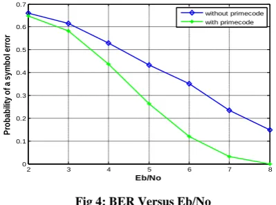
On compared to bandwidth of phase shift keys, M-ary FSK needs comparatively large bandwidth. The graph below shows the comparisons performance of both schemes below:
2 3 4 5 6 7 8
0 0.1 0.2 0.3 0.4 0.5 0.6 0.7
Eb/No
P
ro
b
a
b
ili
ty
o
f
a
s
y
m
b
o
l e
rr
o
r
without primecode with primecode
Fig 4: BER Versus Eb/No
The following graph implies that FH-SS M-ary Fsk and Prime code has effected by noise, thus interference is occurred.
Since low bit error is shown in Table 1 for Prime code
sequences. Thus high power is saved in this method. The performance of the system using the frequency-hopped
without prime codes is compared with frequency-hopped with prime codes.
4. CONCLUSION
A double length fixed weight of FH pattern is generated for dual media. But in conventional pattern, only either data or video signals can be used in wireless system. A double medium without error correcting code is implemented in system. The number of error is identified and minimizes. The
BER with prime code is compares with BER without prime codes. It has been analyzed that with error correcting code has better spectral efficiency and minimum interference.
5. REFERENCES
[1] Sung-Ming Wu, Guu-Chang Yang, 2011 A Two-Level FH- CDMA Scheme for Wireless Communication Systems over Fading Channels.
[2] Jyh-horng wen, chuan-wang chang ,2010An effective cancellation technique of cochannel interference based on multiuser detection scheme for mfsk/fh-ssma systems
[3] Q. Chen, C. Deng, D. Peng and P. Fan 2009 On the serial iterative co-channel Interference cancellation technique for MFSK/FH-SSMA system
[4] Liu Qingge, Yang Dongkai, Zhang Qishan 2008 Concatenated Prime Codes and Quadratic Prime Codes.
[5] Kevin M. Greenan, Ethan L. Miller, Thomas ,J.E.Schwarz, 2008 Optimizing Galois Field Arithmetic for Diverse Processor Architectures and Applications
[6] Abid yahya 2007Design and development of a secure wireless system using frequency hopping spread spectrum
[7] Kevin M. Greenan, Ethan L. Miller, 2007 Analysis and Construction of Galois Fields for Efficient Storage Reliability
[8] Wing C. Kwong, Guu-Chang Yang 2005 Multiple-Length Extended Carrier-Hopping Prime Codes for Optical CDMASystems Supporting Multimedia Services.
[9] G.-C. Yang, S.-Y. Lin, and W. C. Kwong, 2000 MFSK/FH-SSMA wireless systems with double media services over fading channels.
[10] E.A.Geraniotis, 1982 Error probabilities for slow frequency-hopped spread spectrum multiple access communications over fading channels.
[11] G.C. Yang and T. Fuja 1995 Optical orthogonal codes with unequal auto and cross-correlation constraints.
[12] T Mabuchi ,R.Kohno, and H.Imai, 1983 Multihopping and decoding of error-correcting code for MFSK/FH-SSMA systems.
[13] D.J.Goodman,P.S..Henry,and,1980 Frequency-hopped multilevel FSK for mobile radio.
[14] E. Savas and C. K. Koc. Efficient methods for composite field arithmetic. Technical report, Oregon St. Univ.1999.
[15] A. Shamir. How to share a secret. Communications of the ACM, 22(11):612–613, Nov. 1979.
[16] T. Schwarz, S. J. and E. L. Miller. Store, forget, a check: Using algebraic signatures to check remotely administered storage. In Proceedings of the 26th International Conference on Distributed Computing Systems (ICDCS ’06), Lisboa, Portugal, July 2006. IEEE .