Polynomial based Design of CIC Compensation
Filter used in Software Defined Radio for Multirate
Signal Processing
Richa
R. K. Singh
Deptt. of Electronics and Communication Deptt. of Electrical Engineering UIET CSJM University Kanpur MNNIT Allahabad
ABSTRACT
Software defined radio has find important place in modern communication systems where majority of signal processing is performed in the digital domain using programmable DSPs.Digital down conversion (DDC) is one of the core technologies in SDR, as well as an important component of digital intermediate frequency receiver system. DDC use CIC decimation filters for sample rate decimation. CIC decimation filters require less computation but large passband droop occurs in the frequency response. This paper presents a simple design of compensation FIR filter for CIC decimation filter which will correct the passband droop. Compensation filter design consists of polynomial based design of FIR filter which are used in cascade with CIC filter. As proposed filter depends on simple transformation less approach and computation is required. The resulting structure is multiplier less and exhibits small passband droop in comparison to CIC filter. It modifies the frequency response of CIC decimation filter while maintaining the linear phase.
General Terms
Digital Signal Processing
Keywords
CIC, Decimation, Multirate filter, Linear Phase
1.
INTRODUCTION
The power consumption in context of software defined radio can be reduced by designing a system that has low rate of multiplication and addition operations. Sampling rate reduction (decimation) from a high ADC sampling rate to a small multiple of the symbol rate is a key functionality in a digital radio receiver. The standards to be supported by a software radio platform are often based on incommensurate clock/symbol rates. This makes the sample rate interpolation and decimation a critical functionality in multi standard radio design [9] and [10]. The sampling rate conversion (SRC) can be seen as a process of resampling, thus in spectral domain repetitions of the input signal spectrum are expected. If the original signal is not band-limited, the different spectral replicas will overlap after downsampling. This overlapping in the spectral domain, known as aliasing, sometimes changes the signal irreversibly. Similarly, after interpolation (upsampling) the spectrum repeats itself at the multiples of the sampling rate. These are called image spectra, and the phenomenon itself imaging [11]. These two phenomena must be avoided by the SRC system in order to preserve the signal content. This paper presents a specific power efficient method for decimation with appropriate frequency response. This concept has been
developed for the first stage of the decimation chain of a multistandard radio receiver previously also [3]-[6].
The structures presented here are cascades of CIC decimation and simple polynomial-based filter finite-impulse response (FIR) filter [12].The key point is to design the FIR filterso that the frequency response droop remain minimum and filtering performance of the overall structure remain at the same level [8]. The FIR filter is generally implemented in a non-recursive way which guarantees a stable filter.FIR filter design essentially consists mainly of two parts approximation problem and realization problem. The approximation stage takes the specification and gives a transfer function through few steps [26]. In this method a desired or ideal response is chosen, usually in the frequency domain, then an allowed class of filters is chosen (e.g. the length N for a FIR filters). A measure of the quality of approximation is selected .Finally a method or algorithm is selected to find the best filter transfer function .The realization part deals with choosing the structure to implement the transfer function which may be in the form of circuit diagram or in the form of a program .There are essentially three well-known methods for FIR filter design namely, window method, frequency sampling technique and optimal filter design methods [26]-[30]. In this paper we will present an approach to realize compensation FIR filters using polynomials. The polynomial approach to design filters had been discussed in various papers [15]-[25], but here, a special type of transformation is used along with polynomial approach to design compensation FIR filter. This method is very simple in terms of computation and approach. Also this method has lot of variations so that we can define more than one type of FIR filter from one set of specification.
The paper is organized as follows. In Section 2, the fundamentals of CIC filters for sampling rate conversion (SRC) are discussed. The novel compensation filter design method is presented in Section 3. The novel structure, which is the main contribution of this paper, consists of a fixed polynomial-based filter FIR filter and that works at low output sampling rate. An example application using this novel structure is discussed in Section 4. In Section 5, we show the performance and advantages of the proposed method by means of illustrative examples. Finally, we draw some conclusions in Section 6.
2.
CIC FILTER FOR SAMPLING RATE
CONVERSION
addition operation. The transfer function of the CIC filter can be written in equation 1.
𝐻 𝑧 = 1−𝑧1−𝑧−𝑅−1 𝑁
(1)
where, R and N are the decimation rate and order of the CIC filter. CIC filter has lot of advantages mainly of being multiplierless device including only simple adder and delay model. VLSI implementation is very easy as same section is used repetitively. CIC decimation filter make the circuit to work at low frequencies as well as low power dissipation.
In case of large stop band attenuation the number of stages also increases as a result CIC filter frequency response does not have a wide, flat passband. To achieve the frequency response correction a FIR filter that has a magnitude response, inverse of the CIC filter can be applied. Such filters are called compensation filters [2]. The frequency response of an
Figure1: Cascaded structure of CIC and Compensation filter
In DDR the compensation filter always follows the CIC filter [31]. In other words, the compensation filter always operates at the lower rate in a rate conversion design. One benefit of running the compensation filter at the low rate is to achieve a more efficient hardware solution, that is, more time sharing in the compensation FIR filter.
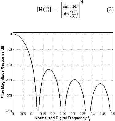
Magnitude response for CIC filter will be given as where M=differential delay usually having value 1or 2, N= number of CIC stages and R is the decimation factor.
H f = sin πMf
sin π fR N
(2)
Figure 2: Frequency response of a CIC filter
The frequency response of CIC filter is shown above in fig.2. The compensation filter will correct the passband droop caused by CIC filter. Its magnitude response will be given as inverse of the CIC filter response as shown in equation 3 [1], [2].
G f = MR Sin (πf/R)sin πMf (3)
≈ sin (πMf )πMf 𝑁 (4)
In case of large R, the compensation filter response can be approximated by the inverse sinc function.
[image:2.595.62.249.520.716.2]≈ sinc−1 Mf N (5)
Figure 3: Ideal frequency response of compensator filter
[image:2.595.325.544.530.675.2]The frequency response of ideal compensation filter is shown above in figure 3.Compensation filter is also use to define transition band of CIC filter specifically; it can also be used as rate conversion filter for decimating usually by a factor of two. The resultant frequency response of cascaded structure is shown in figure 4.
Figure 4: Frequency response comparison of all structures
3.
PROPOSED
COMPENSATION
FILTER
Proposed compensation filter design has two main design steps:
1. Compensation filter order and other specifications are decided according to passband droop which occurs due to CIC filter.
2. Design compensation FIR filter using polynomial based method.
3.1 Compensation Filter Specification Decision
Passband droop due to CIC filter can be given as
dck =
sin π N Fm
Fx
𝑁 sin π N Fm
Fx
K
(6)
where 𝐹𝑚 is maximum input signal frequency of decimator and 𝐹𝑥 is input signal sampling frequency. Passband droop
shown in fig.5 will be used to decide passband ripple and order of compensation filter.
[image:3.595.337.513.252.355.2]
Figure 5: Ideal frequency response of CIC filter
3.2 Compensation FIR Filter Design
Compensation filter is designed using proposed method [8]: 1. First transform the required filter characteristics to a function, which we call as object function, by using a special transformation.
2. This object function is thereafter realized by using a previously defined set of polynomials.
3. The realized object function is then converted back to filter characteristics using inverse of the transform used in step 1. The transformation and its inverse is used to design compensation filter in the present discussion [21]. Suppose we need to design a filter with characteristics H(ω) . First, we apply the inverse of the transformation on the filter characteristics H(ω) and it results in an object function f (x) as shown in fig.6. Object function thus calculated and the desired filter definition is inverse of each other. Let us consider a polynomial as an object function where the values of xi’s
are all equal to 0; that is, all the zeros of the object function lie on the
origin. In this case the polynomial considered as object function is
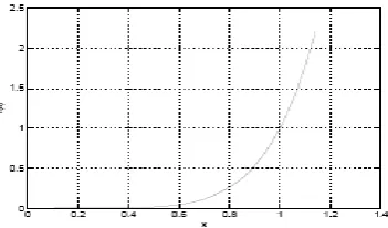
f(x) = x6 (7)
The value of the function, where we want our stop band to start, can be taken at x = 1 .Therefore, at the start of the stop band
[image:3.595.66.273.359.513.2]
x6 = 1 (8) Also the transformation x = x0 cos (ω/2) is chosen here and x0 is the maximum value of x. Looking at the object function and transformation it is clear that x = 0 transforms to ω = π and x = 1 transforms to ω = 2 cos−1(1/x0) which is the frequency where the stop-band starts.
Fig 6: Graphical representation of polynomial x6
3.2.1
Calculation Of Stopband Frequency, ωs,
And Passband Frequency, ωp of
Compensation Filter
Using the method given in [8] we can calculate the stopband frequency, passband frequency of the desired compensation filter. It is desired that at x = x0 the value of the function f (x0) should be ’b’ times its value than it has at the stopband. Thus,
(x0)n = b (9) So, x0 = (b)
1/n (10)
As it is assumed that at the stop band frequency x=1 so putting these values in transformation equation
1 = (b)1/n (11)
and stopband frequency will be to
ωs = 2 cos−1(1/(b)1/n) (12)
Similarly passband frequency will occur when function is at 3db down of its peak value than that at stop band so
xpn = b/√2 (13)
where xp is corresponds to passband frequency in object function. Calculation gives the value of passband frequency
ωp = 2 cos−1(1/21/2n) (14)
Stopband frequency of compensation filter can be given by
Value of constant b will be given as function of p where p is stopband attenuation value in dB. Stopband attenuation p of compensation filter is known in advance from the CIC filter magnitude response. The maximum value of the object function is b times its value than that at the stopband. So value of b will be
b = 10p/20 (16)
4. EXAMPLE APPLICATION
[image:4.595.112.479.329.503.2]As an example we will consider a decimator system with specifications as listed in Table1. In the first step a decimator is designed which decimates by 10 using CIC filter implements the rate change with differential delay M = 1 and number of stages N = 9.
Table 1: Specification of a Decimator system
Specification Value
Input Sampling Frequency 80Mhz Output sampling frequency 10 MHz
Passband edge 4 MHz
Passband ripple 0.05 dB
Stopband attenuation 80 dB
Large numbers of stages are required to achieve the stopband attenuation as specified. The frequency response of CIC filter is
plotted using FDATOOL on MATLAB as shown in figure 7. It is clear from the frequency response that passband has a significant droop. Fig.8 shows the zoomed view of CIC filter response which shows the unavailability of well defined transition width. To overcome this droop and to define proper transition width a compensation filter is designed using proposed method.
Compensation filter order is decided by considering small passband ripple and narrow transition width given in table 1. Using proposed method passband frequency and stopband frequency are calculated. If n =110 and value of b= 10000 if passband attenuation is 60 dB, corresponding values of stopband frequency and passband frequencies are of ωs is 2.17622 radians and ωp is 0.6733 radians respectively. Frequency response of cascaded structure can be plotted using normalized value of frequencies which will give less passband droop.
[image:4.595.109.483.537.729.2]
5. SIMULATION RESULT
Figure 7: Frequency response of CIC filter for given specifications
Figure 8 : Zoomed view of frequency response of CIC filter for given specifications
0 0.1 0.2 0.3 0.4 0.5 0.6 0.7 0.8 0.9
-200 -150 -100 -50 0
Normalized Frequency ( rad/sample)
M
a
g
n
itu
d
e
(
d
B
)
(n
o
rm
a
liz
e
d
t
o
0
d
B
)
Magnitude Response (dB)
0 0.05 0.1 0.15 0.2 0.25 0.3 0.35 0.4 0.45
-200 -150 -100 -50 0
Normalized Frequency ( rad/sample)
M
a
g
n
it
u
d
e
(
d
B
)
(n
o
rm
a
liz
e
d
t
o
0
d
B
)
Figure 9: Frequency response of compensation filter for given specifications
Fig 10: Frequency response of cascaded filter with improved stopband attenuation
The compensation filter is a single rate FIR filter operating at 10 MHz. Its passband edge is decided to be 4.10 MHz by proposed method; slightly larger than the required passband edge 4.0 MHz .The filter order L, is chosen to be 110. The large filter order is necessary to meet the small pass band ripple requirement and the narrow transition bandwidth requirement.Frequency responses are plotted using FDA Tools on MATLAB. Fig.9 shows the frequency response of compensation filter. Fig 10 shows the improved frequency response of cascade of CIC filter and compensation filter. Fig. 10 shows the improvement in stop band attenuation. Comparing the responses shows that compensation filter improvement is around 30dB in stopband attenuation. It is also evident from the responses that proposed compensation filter produces well defined transition width. Here polynomial based filter design is used, so less computation is required. Also as passband droop is calculated theoretically we can practically see that using proposed method better results are achieved [7].
6.
CONCLUSION
As novel simple design is used for compensation filter less computation is required to design cascade of CIC and compensation filter now. On using proper polynomial passband droop can be reduced at maximum level and without much increase in complexity in comparison to previous proposed methods. In case of more passband droop we can use the
filter also help to define frequency response more close to ideal values Also multistage filtering can be done in order to reduce the sampling rate at first stage .VLSI implementation is also possible and implementation can be checked and verified on popular FPGA series as VIRTEX and SPARTAN etc.
7. REFERENCE
[1] Eugene B, Hogenuer,1981” An economical class of digital filter for decimation & interpolation” IEEE Transaction on Acoustics, speech & signal processing (April 1981) 155-162.
[2] Altera’s application note 455 April 2007, “Understanding CIC compensation filter” ver. 1.0.
[3] G. Jovanovic Dolecek and Sanjit K. Mitra 2008, “Á Simple Method for the Compensation of CIC Decimation Filter,” Electronics letters, IET (former IEE) UK, vol.44, Issue 19, 1162-1163.
[4] G. Jovanovic Dolecek, “Simple wideband CIC compensator”, Journal IET Electronics Letters, 19th November, 2009, vol.45, No.24, 1270-1272
[5] Kim, S., Lee, W.C., Alm, S., and Choi, S.2006 “Design of CIC roll off compensation filter in a W-CDMA digital receiver”, Digital Signal Process, (2006), 16, 846-854.
0 0.1 0.2 0.3 0.4 0.5 0.6 0.7 0.8 0.9
-100 -80 -60 -40 -20 0
Normalized Frequency ( rad/sample)
M
a
g
n
itu
d
e
(
d
B
)
(n
o
rm
a
liz
e
d
t
o
0
d
B
)
Magnitude Response (dB)
0 0.05 0.1 0.15 0.2
-250 -200 -150 -100 -50 0
Normalized Frequency ( rad/sample)
M
a
g
n
itu
d
e
(
d
B
)
(n
o
rm
a
liz
e
d
t
o
0
d
B
)
[6] Gordana Jovanovic Dolecek and Fernando Javier Trejo Torres. “Compensated CIC cosine Decimation filter”.
[7] Ljiljana Milić 2009 Multirate Filtering for Digital Signal Processing: MATLAB Applications “Information science refeernce Hershey Newyork .
[8] Vinay Kumar and Sunil Bhooshan, 2006“Designing FIR Filters with Polynomial Approach”,World Academy of Science,Engineering and Technology vol.22..
[9] T. Hentschel and G. Fettweis, 1999 Software radio receivers. CDMA Techniques for Third Generation Mobile Systems, Kluwer Academic Publishers, Dordrecht
[10] T. Hentschel and G. Fettweis, Sample rate conversion for software radio, IEEE Commun. Mag. (August 2000), 142–150.
[11] R.E. Crochiere and L.R. Rabiner, 1983 “ Multirate Digital Signal Processing, Prentice-Hall, Englewood Cliffs, NJ.
[12] M. Henker, T. Hentschel, G. Fettweis,1999 “ Time-variant CIC-filters for sample-rate conversion with arbitrary rational factors, Proceedings of the IEEE Sixth International Conference on Electrical Circuits and Systems, Paphos, Cyprus.
[13] L.Lundheim and T.A. Ramstad,1999 “ An efficient and flexible structure for decimation and sample rate adaptation in software radio receivers, Proceedings of the Fourth ACTS Mobile Communications Summit (AMOS), Sorrento, Italy.
[14] D. Babic, J. Vesma, M. Renfors,2001 “ Decimation by irrational factor using CIC filter and linear interpolation, in: Proceedings of the International Conference on Acoustics, Speech and Signal Processing, ICASSP2001, Salt Lake City, USA.
[15] Boite R. and H. Leich, 1981”A New Procedure for the Design of High Order Minimum Phase FIR Digital or CCD Filters”, Signal Processing, vol. 3, (1981), 101-108.
[16] Herman O. and H.W. Schussler, 1970 ”Design of Non Recursive Digital Filters with Minimum Phase”, Electronics Letters, vol. 6, (1970),329-330.
[17] Stathaki, T.; Constantinides, A.; Stathakis, G, 1998 “Minimum phase FIR filter design from linear phase systems using root moments”, International Conference on
Acoustics, Speech, and Signal Processing, 1998. ICASSP ’98, Proceedings of the1998 IEEE Volume 3, 1317 – 1320.
[18] Mian G.A. and A.P. Naider,“A Fast Procedure to Design Equiripple Minimum Phase FIR FIlters” , IEEE Trans. on Circuits and Systems, vol. 29, no. 5,(1982), 327-331.
[19] T.Stathaki, “Root moments: a digital signal-processing perspective” IEE Proc.- Vis. Image Signal Process., Vol. 145, No. 3, August (1998), 293-302.
[20] Tanskanen, J.M.A.; Dimitrov, V.S, 1999 “Round-off error free fixed-point design of polynomial FIR predictors” , Conference on Signals, Systems, and Computers.
[21] Fotinopoulos, I.; Stathaki, T, 2000 “Equiripple minimum phase FIR filter design from linear phase systems using a novel technique for polynomial factorisation”, Global Telecommunications Conference, 2000. GLOBECOM ’00. IEEE Volume 3, 27 Nov.-1 Dec. 2000, 1659-1663.
[22] Kamp Y. and Wellekens C.J., “Optimal design of minimum phase FIR filters ”, IEEE Trans. on ASSP, Vol. 31, 1983, 922-926.
[23] A. G. Constantinides, “Spectral transformation for digital filters”,Proc. Inst. Elect. Eng., 1970, 1585-1590.
[24]Swamy, M.N.S.; Thyagarajan, K.S., “Frequency
transformations for digital filters”, Proceedings of the IEEE Volume 65, Jan. 1977, 165-166.
[25] Moorer, J., “General spectral transformations for digital filters”,Acoustics, Speech, and Signal Processing, IEEE Transactions on Volume 29, Oct 1981, 1092 – 1094.
[26] Proakis J.G., “Digital Signal Processing: Principles, Algorithms and Applications”, Prentice Hall of India, 3rd Edition.
[27] T.W. Parks and C.S. Burrus, 1987, “Digital Filter Design. New York: Wiley.
[28] L.R. Rabiner and B. Gold, 1975, “Theory and Applications of Digital Signal Processing.New Jersey: Prentice-Hall.
[29]J.G. Proakis and D.G. Manolakis, 2000 “Digital Signal Processing- Principles, Algorithms and Applications New Delhi: Prentice-Hall.
[30] L.R. Rabiner, B. Gold and C.A. McGonegal, “An approach to the Approximation Problem for Nonrecursive Digital Filters,” IEEE Trans. Audio and Electroacoustics, vol. AU- 18, June 1970, 83-105.