© 2018, IRJET | Impact Factor value: 6.171 | ISO 9001:2008 Certified Journal
| Page 1673
DESIGN OF SOFT COMPUTING CONTROL TECHNIQUES FOR TWO AREA
LOAD FREQUENCY CONTROL
T.Dinesh
1Dr. T. Anil Kumar
21
Assistant Professor, Anurag Group of Institutions(CVSR),Venkatapur(V),Ghatkesar(M)
2
Professor, Anurag Group of Institutions(CVSR),Venkatapur(V),Ghatkesar(M)
---***---
Abstract- In this work we analyze and design Automatic load frequency control of two area power system using Fuzzy based PI Control and Fuzzy Logic Control, generation control is becoming increasingly important in view of increased load demand & reducing generating resources. The increasing load demands are posing serious threats to reliable operation of power systems. As we all know that Maintaining power system frequency at constant value is very important for the quality of the power generating equipment and the utilization equipment at the customer end. The job of automatic frequency regulation is achieved by governing systems of individual turbine- generators and Automatic Generation Control (AGC) or Load frequency control (LFC) system of the power system. The healthy and undamaged operation of generator needs the control of the following parameters: (a) Frequency to be maintained constant (b) the tie line power to be maintained between specified limits. If the above parameters are maintained with in desired limits the generation control is said to be most effective. The main objective of automatic generation control is to maintain the balance between the generation and demand of a particular power system. A power system model has been simulated within a MATLAB environment. A comparative study between the frequency responses of the system using Fuzzy Based PI control has been proposed which boosts of its superiority over a Fuzzy PI control in terms of its settling time and peak overshoot and its simplicity of realization.
Key Words – Load Frequency Control (LFC), PI Controller, Fuzzy Based PI Controller, Artificial Neural Network (ANN).
I. INTRODUCTION
For large scale electric power systems with interconnected areas, Load Frequency Control (LFC) is important to keep the system frequency and the inter-area tie power as near to the scheduled values as possible. The input mechanical power to the generators is used to control the frequency of output electrical power and to maintain the power exchange between the areas as scheduled. A well designed and operated power system must cope with changes in the load and with system disturbances, and it should provide acceptable high level of power quality while maintaining both voltage and frequency within tolerable limits. Load frequency control is basic control mechanism in the power system operation. Whenever there is variation in load demand on a generating unit, there is a momentarily an occurrence of unbalance between real-power input and output. This difference is being supplied by the stored energy
of the rotating parts of the unit. Load Frequency Control (LFC) is being used for several years as part of the Automatic Generation Control (AGC) scheme in electric power systems. One of the objectives of AGC is to maintain the system frequency at nominal value (50 Hz) [1-2].
Automatic generation control (AGC) is defined as, the regulation of power output of controllable generators within a prescribed area in response to change in system frequency, tieline loading, or a relation of these to each other, so as to maintain the schedules system frequency and / or the established interchange with other areas within predetermined limits. The two basic inter-area regulating responsibilities are as follows:- (i) When system frequency is on schedule, each area is expected automatically to adjust its generation to maintain its net transfer with other areas on schedule, thereby absorbing its own load variations. As long, all areas do so; scheduled system frequencies as well as net interchange schedules for all area are maintained.
(ii) When system frequency is off-schedule, because one or more areas are not fulfilling their regulating responsibilities, other areas are expected automatically to shift their respective net transfer schedules proportionally to the system frequency deviation and in direction to assist the deficient areas and hence restore system frequency. The extent of each area’s shift of net 28 interchange schedule is programmed by its frequency bias setting. Therefore, a control strategy is needed that not only maintains constancy of frequency and desired tie-power flow but also achieves zero steady state error and inadvertent interchange. Numbers of control strategies have been employed in the design of load frequency controllers in order to achieve better dynamic performance.
II. CONCEPT OF LOAD FREQUENCY CONTROL
The active and reactive power demands are never steady and they continuously changes with the rising or falling trend of load demand. There is a change in frequency with the change in load which causes problems such as:
1. Most AC motors run at speeds that are directly related to frequency. The speed and induced electro motive force (e.m.f) may vary because of the change of frequency of the power circuit.
© 2018, IRJET | Impact Factor value: 6.171 | ISO 9001:2008 Certified Journal | Page 1674 3. The change in frequency can cause mal operation of power
converters by producing harmonics.
4. For power stations running in parallel it is necessary that frequency of the network must remain constant for synchronization of generators [3-6].
In the steady state operation of power system, the load demand is increased or decreased in the form of Kinetic Energy stored in generator prime mover set, which results the variation of speed and frequency accordingly. Therefore, the control of load frequency is essential to have safe operation of the power system.
Neglecting resistances
Small power changes mainly depends on or f . Moreover, frequency is also a major stability criterion for large-scale stability in multi area power systems. To provide the stability, a constant frequency is required which depends on active power balance. If any change occurs in active power demand/ generation in power systems, frequency cannot be hold as its rated value. Hence, oscillations increase in both power and frequency[7-8]. Thus, the system is subjected to a serious instability problem. To improve the stability 34 of the power networks, it is necessary to design load frequency control (LFC) systems that control the power generation and active power at tie lines of interconnected system. In interconnected power networks with two or more areas, the generation within each area has to be controlled to maintain the scheduled power interchange. Load frequency control scheme has two main control loops. These are primary control and secondary control loops. This action has been realized by using a turbine-governor system in the plant[9-10] .
Basically, single area power system consists of a governor, a turbine, and a generator with feedback of regulation constant. System also includes step load change input to the generator. This work mainly, related with the controller unit of a single area power system. The load frequency control strategies have been suggested based on the conventional linear Control theory. These controllers may be unsuitable in some operating conditions due to the complexity of the power systems such as nonlinear load characteristics and variable operating points. To some authors, variable
[image:2.595.308.561.258.376.2]structure control maintains stability of system frequency [11-12]. However, this method needs some information for system states, which are very difficult to know completely. Also, the growing needs of complex and huge modern power systems require optimal and flexible operation of them. The dynamic and static properties of the system must be well known to design an efficient controller. Under normal operating condition controller are set for small changes in load demand without voltage and frequency exceeding the pre specified limits. If the operating condition changes by any cause, the controller must be reset either manually or automatically. The objective of load frequency controller is to exert the control off frequency and at the same time real power exchange via outgoing transmission line.
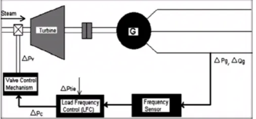
Fig.2.1 Load frequency control in single area power system
The frequency is sensed by frequency sensor. The change in frequency and tie line real power can be measured by change in rotor angle δ. The load frequency controller amplify and transform error signal, i.e., (Δfi and ΔPtie) in to real power command signal ΔPci which is sent to the prime mover via governor (that control the valve mechanism). To call for an increment or decrement in torque the prime mover balances the output of governor which will compensate the value of error signal that is Δfi and ΔPtie. The process continues till deviation in form of Δfi and ΔPtie as well as the specified tolerance[13-14].
[image:2.595.311.553.639.758.2]The LFC problem in power systems has a long history. In a power system, LFC as an ancillary service acquires an important and fundamental role to maintain the electrical system reliability at an adequate level. It has gained the importance with the change of power system structure and the growth of size and complexity of interconnected systems.
© 2018, IRJET | Impact Factor value: 6.171 | ISO 9001:2008 Certified Journal | Page 1675 The LFC model given in Fig.2 uses three simple (first order)
transfer functions for modeling the turbine, generator and power system (load and rotating mass). The effects of local load changes and interface with other areas are properly considered as two input signals. Each control area monitors its own tie-line power flow and frequency at the area control center. The area control error (ACE) which is a linear combination of tie-line and frequency errors is computed and allocated to the controller K(s). Finally, the resulted control action signal or a percentage of it is applied to the turbine-governor unit. The operation objectives of the LFC are summarized to maintain system frequency close to nominal value, to control the tie-line interchange schedules, and to divide the load between generator units. Commonly, a simple integral or proportional-integral control law is used as controller K(s) to perform LFC task [15-17]. A multi-area power system is comprised of areas that are interconnected by high-voltage transmission lines or tie-lines. The trend of frequency measured in each control area is an indicator of the trend of mismatch power in the interconnection and not in the control area alone. Therefore, following a load disturbance within a control area or an occurred mismatch power on tie-lines, the frequency of that control area experiences a transient change. The feedback mechanism comes into play and generates the appropriate signal to the turbine for tracking the load variation and compensates the mismatch power.
Depending on the type of generating units, and constraints on their range and rate of response to the LFC signals, the actual response time (for example for a steam unit) takes a few to several tens of seconds. In LFC practice, rapidly varying components of system signals are almost unobservable due to filters involved in the process. That is why further reduction in the response time of LFC is neither possible nor desired. Practically, the design and performance of an LFC system highly dependent on how generation units respond to control signal. Such control strategies are useful as they are able to maintain a sufficient level of reserved control range and a sufficient level of control rate. In light of this fact, although the present dissertation uses some academic examples (and data) in which the assumed parameters (and in result, dynamics of the simplified models) are not completely matched to real ones, and gives the impression that the output of the models can be changed quickly, however the proposed control strategies are flexible enough to set a desired level of performance to cover the practical constraint on the control action signals. Since the 1970s, the described LFC scheme in Fig.2 is widely used by researchers for the LFC analysis and synthesis.
III. DESIGN OF CONTROLLERS FOR LFC
P-I controller
P-I controller is mainly used to eliminate the steady state error resulting from P controller. However, in terms of the speed of the response and overall stability of the system, it has a negative impact. This controller is mostly used in areas
[image:3.595.334.539.145.228.2]where speed of the system is not an issue. Since P-I controller has no ability to predict the future errors of the system it cannot decrease the rise time and eliminate the oscillations. If applied, any amount of I guarantees set point overshoot.
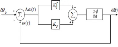
Fig 3.1 Block diagram of PI controller
PI controller an integral error compensation scheme, the output response depends in some manner upon the integral of the actuating signal. This type of compensation is introduced by a using a controller which produces an output signal consisting of two terms, one proportional to the actuating signal and the other proportional to its integral. Such a controller is called proportional plus integral controller or PI controller [18-22].
Fuzzy Logic
In recent years, the number and variety of applications of fuzzy logic have increased significantly. The applications range from consumer products such as cameras, camcorders, washing machines, and microwave ovens to industrial process control, medical instrumentation, decision-support systems, and portfolio selection.
To understand why use of fuzzy logic has grown, you must first understand what is meant by fuzzy logic.
Fuzzy logic has two different meanings. In a narrow sense, fuzzy logic is a logical system, which is an extension of multi valued logic. However, in a wider sense fuzzy logic (FL) is almost synonymous with the theory of fuzzy sets, a theory which relates to classes of objects with unsharp boundaries in which membership is a matter of degree. In this perspective, fuzzy logic in its narrow sense is a branch of FL. Even in its more narrow definition, fuzzy logic differs both in concept and substance from traditional multivalued logical systems.
© 2018, IRJET | Impact Factor value: 6.171 | ISO 9001:2008 Certified Journal | Page 1676 Another basic concept in FL, which plays a central role in
most of its applications, is that of a fuzzy if-then rule or, simply, fuzzy rule. Although rule-based systems have a long history of use in Artificial Intelligence (AI), what is missing in such systems is a mechanism for dealing with fuzzy consequents and fuzzy antecedents. In fuzzy logic, this mechanism is provided by the calculus of fuzzy rules. The calculus of fuzzy rules serves as a basis for what might be called the Fuzzy Dependency and Command Language (FDCL). Although FDCL is not used explicitly in the toolbox, it is effectively one of its principal constituents. In most of the applications of fuzzy logic, a fuzzy logic solution is, in reality, a translation of a human solution into FDCL.
A trend that is growing in visibility relates to the use of fuzzy logic in combination with neuro computing and genetic algorithms. More generally, fuzzy logic, neuro computing, and genetic algorithms may be viewed as the principal constituents of what might be called soft computing. Unlike the traditional, hard computing, soft computing accommodates the imprecision of the real world. The guiding principle of soft computing is: Exploit the tolerance for imprecision, uncertainty, and partial truth to achieve tractability, robustness, and low solution cost. In the future, soft computing could play an increasingly important role in the conception and design of systems whose MIQ (Machine IQ) is much higher than that of systems designed by conventional methods.
Among various combinations of methodologies in soft computing, the one that has highest visibility at this juncture is that of fuzzy logic and neuro computing, leading to neuro-fuzzy systems. Within neuro-fuzzy logic, such systems play a particularly important role in the induction of rules from observations. An effective method developed by Dr. Roger Jang for this purpose is called ANFIS (Adaptive Neuro-Fuzzy Inference System). This method is an important component of the toolbox.
Fuzzy logic is all about the relative importance of precision: How important is it to be exactly right when a rough answer will do?
You can use Fuzzy Logic Toolbox software with MATLAB technical computing software as a tool for solving problems with fuzzy logic. Fuzzy logic is a fascinating area of research because it does a good job of trading off between significance and precision—something that humans have been managing for a very long time.
In this sense, fuzzy logic is both old and new because, although the modern and methodical science of fuzzy logic is still young, the concepts of fuzzy logic relies on age-old skills of human reasoning.
Fuzzy logic is a convenient way to map an input space to an output space. Mapping input to output is the starting point for everything. Consider the following examples:
With information about how good your service was at a restaurant, a fuzzy logic system can tell you what the tip should be.
With your specification of how hot you want the water, a fuzzy logic system can adjust the faucet valve to the right setting.
With information about how far away the subject of your photograph is, a fuzzy logic system can focus the lens for you.
With information about how fast the car is going and how hard the motor is working, a fuzzy logic system can shift gears for you.
Now that you understand the fuzzy inference, you need to see how fuzzy inference connects with logical operations.
The most important thing to realize about fuzzy logical reasoning is the fact that it is a superset of standard Boolean logic. In other words, if you keep the fuzzy values at their extremes of 1 (completely true), and 0 (completely false), standard logical operations will hold. As an example, consider the following standard truth tables.
[image:4.595.310.552.381.499.2]1)
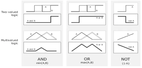
Fig.3.2 Truth Table
Now, because in fuzzy logic the truth of any statement is a matter of degree, can these truth tables be altered? The input values can be real numbers between 0 and 1. What function preserves the results of the AND truth table (for example) and also extend to all real numbers between 0 and 1?
One answer is the min operation. That is, resolve the statement A AND B, where A and B are limited to the range (0,1), by using the function min(A,B). Using the same reasoning, you can replace the OR operation with the max function, so that AOR B becomes equivalent to max(A,B). Finally, the operation NOT A becomes equivalent to the operation 1−A. Notice how the previous truth table is completely unchanged by this substitution.
Moreover, because there is a function behind the truth table rather than just the truth table itself, you can now consider values other than 1 and 0.
© 2018, IRJET | Impact Factor value: 6.171 | ISO 9001:2008 Certified Journal | Page 1677 preceding two-valued truth tables, while the lower part of
[image:5.595.41.282.140.255.2]the figure displays how the operations work over a continuously varying range of truth values A and B according to the fuzzy operations you have defined.
Fig 3.3 Plot of two Fuzzy sets
ANN (Artificial Neural Network)
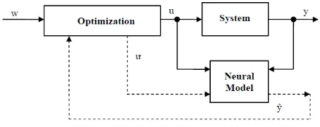
For purposes of nonlinear system control, it is important to have accurate models. Thanks to a very good approximating ability of multi-layer perceptron networks (MLP) we are able to create accurate neural models of nonlinear processes. For purpose of control of nonlinear dynamic systems, several control structures using neural models and inverse neural models have been developed, and this article deals with them.
Neural model of process is represented by three-layer artificial neural network of MLP type. The objective of MLP network is to approximate the relation of system output in k-th step on basis of past values of system output and input and thus get feed-forward neural model. Than we can describe nonlinear dynamic system by following model:
yˆ(k +1) = f [ y(k),y(k −1),K,y(k − n +1),u(k),u(k −1),K,u(k − m +1)] (1)
where u- process input, y- process output, n- order of process output , m- order of process input, nonlinear function, k- discrete time ( t = k *Tvz , Tvzis sampling period). For purpose of system control, we used inverse neural model, which we get by exact inversion of model from equation (1) by expressing controller output u(k):
[image:5.595.321.549.299.394.2]u(k) = f −1[ yˆ(k +1), y(k), y(k −1),K,y(k − n +1),u(k −1),K,u(k − m +1)] (2)
Fig 3.4 Modelling block scheme using artificial neural network
Neural controllers for control of nonlinear processes are using inverse neural models. We’ve chosen following neural controllers to compare the control performance of nonlinear processes:
Robust direct inverse neural control,
Internal model control with neural models,
Predictive neural control
In direct inverse control, inverse model described by equation (2) is used. We used predicted value yˆ(k +1) known from the set of input-output data while training the inverse model. In closed-loop circuit the predicted value yˆ(k +1) is replaced by reference valuew(k +1), and thereby we get closed-loop neural controller out of the inverse model. In Fig.7 is shown a block scheme of direct inverse control.
Fig 3.5 The scheme of direct inverse neural control
[image:5.595.318.552.499.599.2]Direct inverse control as shown in Fig.7 can not remove permanent reference error when the system parameters changed, or disruption occurs. Therefore an adapting block which adapts neuron threshold value in output layer of neural network is added to control.
Fig 3.6 The scheme of robust direct inverse neural control
In Fig.8 is displayed a block scheme of robust inverse control, where the adapter is as a simple integrator in form: B = 1+βΣ(w− y)
where β is adaptive parameter from range 0 to 1.
[image:5.595.54.281.647.739.2]© 2018, IRJET | Impact Factor value: 6.171 | ISO 9001:2008 Certified Journal | Page 1678 Fig 3.7 The scheme of internal model control with neural
models
[image:6.595.46.273.316.406.2]Predictive neural control uses direct neural model to predict future outputs of process assuming the control variable will be u’. This control variable is optimized in each step of control process, so that predicted value of output yˆ(k + i) step reaches reference value w.
Fig 3.8 The scheme of Predictive neural control
IV. SIMULAITON RESULTS
Simulations are performed using MATLAB-SIMULINK
Fig 4.1 Matlab Circuit of PI Controller
Fig 4.2 Frequency deviation in area1 using PI controller
[image:6.595.331.579.393.581.2][image:6.595.41.293.490.664.2]
Fig 4.3 Frequency deviation in area2 using PI controller
Fig 4.4 Matlab Circuit of Fuzzy Controller
© 2018, IRJET | Impact Factor value: 6.171 | ISO 9001:2008 Certified Journal | Page 1679 Fig 4.6 Frequency deviation in area2 using Fuzzy
Fig 4.7 Matlab Circuit of ANN Controller
[image:7.595.326.559.616.743.2]Fig 4.8 Frequency deviation in area1 using ANN
Fig 4.9 Frequency deviation in area2 using ANN
Fig. 4.10 Area Correction Error deviation in Area 1
Fig. 4.11 Area Correction Error deviation in Area 2
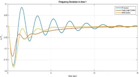
Comparison of PI, Fuzzy and ANN frequency deviation in Area 1 and Area 2
Fig. 4.12 Comparative Frequency deviation in Area 1
[image:7.595.42.264.620.742.2]© 2018, IRJET | Impact Factor value: 6.171 | ISO 9001:2008 Certified Journal | Page 1680
V. CONCLUSION
A PI controller used for load frequency controller of two area interconnected power system has been presented. It can be implemented in four area power system and controlled by using advanced controller systems. The system performance was observed on the basis of dynamic parameters i.e. settling time, overshoot and undershoot. The system performance characteristics reveals that the performance of fuzzy logic controller method better than other controllers. As a further study, the proposed method can be applied to multi area power system load frequency control (ALFC) and also optimum values can be obtained by Genetic Algorithm.
REFERENCES
1. SitthidetVachirasricirikul and IssarachaiNgamroo “Robust LFC in a Smart Grid With Wind Power Penetration by Coordinated V2G Control and Frequency Controller” IEEE TRANSACTIONS ON SMART GRID, VOL. 5, NO. 1, JANUARY 2014
2. K.R.Padiyar, HVDC Power Transmission System Technology and System Interconnections, New International Publishers.
3. M. E. Khodayar, L. Wu, and M. Shahidehpour, “Hourly coordination of electric vehicle operation and volatile wind power generation in SCUC,” IEEE Trans. Smart Grid, vol. 3, no. 3, pp. 1271–1279, Sep.2012.
4. Y. Ota, H. Taniguchi, T. Nakajima, K. M. Liyanage, K. Shimizu, T.Masuta, J. Baba, and A. Yokoyama, “Effect of autonomous distributed vehicle-to-grid (V2G) on power system frequency control,” in Proc.2001 IEEE Ind. Inf. Syst. Conf., pp. 481–485.
5. Z. Fan, “A distributed demand response algorithm and its application to PHEV charging in smart grids,” IEEE Trans. Smart Grid, vol. 3, no.3, pp. 1280–1290, Sep. 2012.
6. M. Takagi, K. Yamaji, and H. Yamamoto, “Power system stabilization by charging power management of plug-in hybrid electric vehicles with LFC signal,” in Proc. 2009 IEEE Veh. Power Propulsion Conf., pp.822–826.
7. Elgerd O I and Charles Fosha E, “Optimum Megawatt- Frequency Control of Multi area Electric Energy Systems”, IEEE Transactions on Power Apparatus and Systems, vol.PAS-89, No 4, April1970, pp. 556-563
8. T. Masuta and A. Yokoyama, “Supplementary load frequency control by use of a number of both electric vehicles and heat pump water.
9. ShayeghiH, JaliliA and Shayanfar HA, “Load Frequency Control Strategies: A State of-the-art survey for the researcher”, Energy Conversion and Management (Elsevier)50 (2009),pp.344-353
10. Christie R D and Bose A, “Load Frequency Control Issues in power system operation after Deregulation”, IEEE Transactions on Power Systems, vol.11, No3, 1996, pp. 191-200.
11. DondeV, PaiM A and HiskensIA “Simulation and Optimization in an AGC System after Deregulation”, IEEE Transactions on Power Systems, vol.16, No 3, Aug 2001, pp.481-489.
12. ElyasRakhshani, JavadSadeh,”Practical view points on load frequency control problem in a deregulated power system”, Energy Conversion and Management 51 (2010) 1148–1156.
13. Demiroren , H.L. Zeynelgil “GA application to optimization of AGC in three-area power system after deregulation” Electrical Power and Energy Systems 29 (2007) 230–240
14. Tan Wen, Zhang H,Yu M, “Decentralized load frequency control in deregulated environments” Electrical Power and Energy Systems 2012;41:16–26.
15. Lili Dong, Yao Zhang, Zhiqiang Gao,” A robust decentralized load frequency controller for interconnected power systems”, ISA Transactions 51 (2012) 410–419
16. Rabindra Kumar Sahu, G.T. Chandra Sekhar, Sidhartha Panda,” DE optimized fuzzy PID controller with derivative filter for LFC` of multi source power system in deregulated environment”, Ain Shams Engineering Journal (2015), Article in press.
17. Ngamroo I., Mitani Y. and Tsuji K., “Robust Load frequency control by solid-state phase shifter based on H∞ control design”, Power Engineering Society Winter Meeting, IEEE, Volume-1,1999,PP 725-730.
18. Shayeghi H., Shayanfar H A., and Jalili A., “LFC Design of a Deregulated Power System with TCPS Using PSO”. World Academy of Science, Engineering and Technology, Volume-3, 2009, PP 556-564.
19. Nathan Cohn, "Some Aspects of Tie-Line Bias Control on Interconnected Power Systems", AIEE Trans., vol. 75, Feb. 1957, pp. 1415-1436.
20. Kumar.P, Ibraheem, “Optimal AGC regulator design of a two-area power system with parallel ac/dc links,” proceedings of Iranian Conference on Electrical Engineering (ICEE),Iran,1993.
© 2018, IRJET | Impact Factor value: 6.171 | ISO 9001:2008 Certified Journal | Page 1681 22. R.Thottungal, P.Anbalagan, T.Mohanaprakash,
A.Sureshkumar and G.V.Prabhu, “ Frequency stabilisation in multi area system using HVDC link,” in proceedings of IEEE international conference on industrial technologies, December,2006, pp.590-595.