© 2018, IRJET | Impact Factor value: 6.171 | ISO 9001:2008 Certified Journal | Page 1368
STUDY AND ANALYSIS OF 'A-FRAME' IN LIGHT UTILITY HELICOPTER
Sohanth Kumar
1, Anil Kumar
2, Dr. Aswatha
3, Pawan. A
41
Post Graduate, Machine Design, Bangalore Institute of Technology, Karnataka, India.
2Assistant Manager, Research and Development Department, BEML Limited, Karnataka, India.
3
Associate Professor, Dept. of Mechanical Engineering, Bangalore Institute of Technology, Karnataka, India.
4
GET, Research and Development Department, BEML Limited, Karnataka, India.
---***---Abstract
-The frame of the Helicopter is made up of trussstructures providing strength for high speed and maneuverability. The project undertaken is a structural part of the frame that helps in transferring the loads from the main gear box unit to the helicopter body structure during the high speed maneuvers of the helicopter. The part is called as an A-Frame. Based on the operations carried out by the helicopter, there are varying types of loads acting on the A-frame. Some of the major loads are generated by Lift, Rotor Torque, Landing and Maneuverability operations. Due to such a wide range of forces, the A-Frame forms a critical part in the structure assembly. Hence, analysis of such a part subjected to various forces is the main criteria of this study.
Key Words:
A-Frame, Light Utility Helicopter, Finite
Element analysis, Lift Load case, Manoeuvrability Load case, Torque, Natural Frequency
1. INTRODUCTION
[image:1.595.336.531.330.421.2]The 'A-Frame' in a helicopter is located in the top part of the welded body structure. It connects the main gear box (MGB) to the welded body structure. It is an assemblage of five parts i.e., a short link, a long link, two end links forming a connection with the frame and a main link which connects the two links to the main gear box. The pictorial representation is as shown in the Fig -1.
Fig -1: A-Frame as assembled on the helicopter
The A-Frame carries out many functions in a helicopter. Some of the functions are listed as below:
a. It stabilizes the position of the MGB by restricting its motion caused due to the torque of the rotor blades and the torque shaft.
b. It transfers the partial load of the MGB to the frame. c. It takes the partial loads during takeoff and landing. d. It takes the loading due to maneuverability of the
aircraft.
e. It protects the MGB from external debris and also plays a role in stopping the debris from entering the inlet of engine.
[image:1.595.335.531.333.556.2]A-Frame assembly is made up of 4 parts which are made of 15CDV6 material and are welded together using TIG welding. The parts of the A-Frame are as shown in Fig -2. The Parts shown in order are namely- main link, End link, long connector and short connector links. A-frame assembly is as shown in Fig -3.
Fig -2: Major parts of A-Frame
Fig -3: A-Frame assembly
The A-Frame being the one of the important parts of the helicopter is acted upon by different load cases during the helicopter operations. Some of the major load cases taken into consideration are:
a. Lift Load: Lift is the force that is generated by the aerodynamic shape of the wing due to the pressure difference in the air passing above and below it. b. Rotor Torque: Torque is a force which when applied
tends the object to move in a circular path about a fixed point.
[image:1.595.82.241.528.622.2]© 2018, IRJET | Impact Factor value: 6.171 | ISO 9001:2008 Certified Journal | Page 1369 d. Maneuverability: The loads acting on the helicopter
structure due to the change in direction of the helicopter in mid-air.
i. Rolling: Rolling is a change in the angle of tilt of the Helicopter from its central axis when viewed from the front.
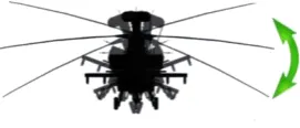
ii. Pitching: Pitching is a change in the angle of tilt of the Helicopter from its central axis when viewed from the side.
iii. Yawing: Yawing is an angular movement of the helicopter about the rotor axis when viewed from the top.
e. Natural frequency: The frequency of a body in its natural state i.e., when no external load is acting on it is known as its natural frequency.
Hence an analysis is carried out in order to determine the response of the A-Frame to the above mentioned forces.
2. LITERATURE REVIEW
A brief review of the important literature related to static and modal analysis of Helicopter frame is carried out and presented in the following section.
Boudon et al. [1] studied about strong vibration levels that are present in many places on a helicopter because of many rotating systems with very different speeds. Vibration control uses insulating elements such as suspensions and active or semi-active solutions. However, solutions were rarely implemented industrially for the link between the main gear box and the aircraft structure because they are generally too strong and energy demanding.
Load factors of the order of 2.5 were found to be achievable by several different maneuvers, and this same value was also attained under actual operating conditions. The largest flight loads, resulted from pull-up maneuvers for the helicopter in which both cyclic- and collective pitch control were applied with suitable phasing as indicated in the study conducted by Gustafson and Crim [2].
Fredrick [3] studied the improvement in the effectiveness of CAS aircraft has increased developments in its technology and the possibility of ATAC. As the CAS aircraft has to operate close to the ground and /or engage in ATAC, maneuverability and agility are its desired attributes and hence its study formed the main objective of this experimental study. The investigation was done by exploring the capabilities of HELCOM programs which were incorporated into fixed wing aircraft. HELCOM is a list of programs which use energy or force balancing methods in order to determine maneuverability and agility parameters. Tilt-rotor aircraft was compared to CAS aircraft and was shown to have better design parameters which were desirable for a high maneuverable and agile aircraft.
Advanced Light Helicopters can be used for Policing Duties, Coast Guard Role, Ambulance role, offshore operations, civil purpose, Disaster relief operations, armed role and High altitude operations. Gear box diagnosis technique was based on cepstrum analysis. The performances of the above technique been compared to the synchronous cepstre method as researched by Amarnath and Preeti [4]. The application of this technique to the vibration frequency emitted by the gear reduction system concludes that it can play a prominent role in the study of gear vibrations.
3. CALCULAION OF LOADS
3.1 Lift Loads
The theoretical calculation of the lift load [5] is as follows: a. Note down the rotor radius. Let it be 'r'.
b. Calculate the area of the circle swept by the rotor during its operation.
(3.1)
c. Calculate the power transferred to the main propeller, P.
Assuming 12% of the power is transmitted to the tail rotor and 3% of the power is lost due to frictional losses [18]. Therefore 85% of the power is transmitted to the main rotor.
d. Calculate power loading, PL.
Power loading is defined as the power delivered by the rotor per unit area covered by the rotor.
(3.2)
e. Calculate Thrust Loading, TL.
Thrust loading is a function of Power loading. It is given as:
(3.3)
This expression is given by McCormick [5].
f. Calculate total thrust of propeller (or lift of the rotor). (3.4)
3.2 Rotor Torque
© 2018, IRJET | Impact Factor value: 6.171 | ISO 9001:2008 Certified Journal | Page 1370 Fig -4: Rotor torque acting on the helicopter
The steps in torque calculation are as shown below:
a. Calculate the power transferred to the main propeller, P. Assuming 12% of the power is transmitted to the tail rotor and 3% of the power is lost due to frictional losses. Therefore 85% of the power is transmitted to the main rotor.
b. Calculate the speed of the rotor, N.
Speed of the rotor is given by speed of the engine divided by the reduction ratio of the gear box i.e.
(3.5)
c. Calculate torque by using the power equation.
(3.6)
Therefore, torque is given by,
(3.7)
3.3 Landing Load
Usually the helicopter lands very smoothly but during a critical component failure, a hard but safe landing is made. Such type of occurrences is rare but consideration of such forces is necessary since we are dealing with aerospace components.
The theoretical calculation of the landing load is as follows:
a. Calculate the weight of the Gear box. The expression is taken from a helicopter design manual [6].
(3.8)
where, QR is Rotor torque for the gearbox at a given HP which is given by [19]:
(3.9)
Assuming 12% of the power is transmitted to the tail rotor and 3% of the power is lost due to frictional losses. Therefore 85% of the power is transmitted to the main rotor.
b. Calculate the weight of the Rotor blades assembly. The Expression is taken from a helicopter design manual [6].
(3.10)
c. Calculate the total weight of the rotor and gearbox assembly.
(3.11)
d. Determine the maximum load factor (g-force that is acting on the helicopter) using historical data.
e. Calculate the load acting on the frame by using the formula given as:
(3.12)
3.4 Maneuverability Loads
a) Rolling
[image:3.595.368.504.402.460.2]Such maneuvers are undertaken when the helicopter wants to take a turn to either of the sides. The magnitude of load is governed by the rate of change in angle of turn.
Fig -5: Rolling in a helicopter
Loading on the frame due to Rolling [7]
a. Calculate vertical lift. Vertical lift is the force acting to lift the helicopter. This is the force which acts in the upward direction when the helicopter rolls. Let the Roll angle be 'φ'
(3.13)
Since the vertical lift is equal to weight of the helicopter (W) in horizontal flight, we can take
(3.13)
b. Calculate turning lift. Turning lift is the lift that occurs due to the pull of the rotor in the direction of turn. It is directly proportional to the angle of roll.
(3.14)
c. As we already know the total lift and vertical lift, we can write that
© 2018, IRJET | Impact Factor value: 6.171 | ISO 9001:2008 Certified Journal | Page 1371 d. Calculate load factor (g-force) for the given lift and
weight. Load factor is defined as the ratio of lift to the weight of the object.
(3.16)
(3.17)
We can see that the load factor is independent of the cruise velocity and is only dependent on the angle of roll.
Also, the equation for turning lift is given by:
(3.18)
b) Pitching
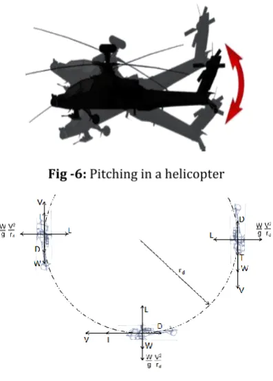
[image:4.595.70.547.17.807.2]Such maneuvers are under taken when the helicopter wants to pull up from a dive or has to increase its altitude. The load factor diagram during various positions of helicopter in flight is as shown in the Fig -7
Fig -6: Pitching in a helicopter
Fig -7: Loads acting on the helicopter during pitching
Loading on the frame due to Pitching
a. Calculate the velocity of the helicopter during autorotation. Let it be 'V'.
b. Find the maximum angle of pitching from historical data [8]. Let the angle be θ.
c. Calculate the rate of descent. By using trigonometry, we can find the rate of descent
Fig -8: Calculation of rate of descent
(3.19)
d. Calculate the approximate radius of flight during the dive. Let it be 'rd'.
e. Determine the total weight of the helicopter. Let it be 'W'.
f. Calculate the lift of the helicopter due to autorotation.
i. First find the area of the rotor or propeller.
(3.20)
ii. Find the approximate speed of the rotor due to Autorotation [9]. Let it be N'.
iii. Find the Horse Power developed by the rotor if the speed of the rotor is reduced to N'.
(3.21)
iv. Calculate power loading, PL.
Power loading is defined as the power delivered by the rotor per unit area covered by the rotor.
(3.22)
v. Calculate Thrust Loading, TL.
Thrust loading is a function of Power loading. This expression is given by McCormick. It is given as:
(3.23)
vi. Calculate total thrust of propeller (or lift of the rotor due to autorotation). Let it be La
(3.24)
g. Calculate the effective weight acting on the helicopter
(3.25)
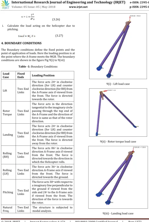
[image:4.595.62.261.365.642.2]© 2018, IRJET | Impact Factor value: 6.171 | ISO 9001:2008 Certified Journal | Page 1372 (3.26)
i. Calculate the load acting on the helicopter due to pitching.
(3.27)
4. BOUNDARY CONDITIONS
[image:5.595.32.539.36.789.2]The Boundary conditions define the fixed points and the point of application of loads. Here the loading position is at the point where the A-frame meets the MGB. The boundary conditions are shown in the figure Fig 9(i) to 9(vii)
Table -1: Boundary Conditions
Load
Case Fixed Ends Loading Position
Lift Two End Links
The force acts 24o in clockwise direction (for LH) and counter clockwise direction (for RH) from the A-Frame axis if viewed from the front. The force is directed towards the rotor.
Rotor
Torque Two End Links
The force acts in the direction tangential to the imaginary circle passing through the top end of the A-Frame and the direction of force is same as that of the rotor direction.
Landing Two End Links
The force acts 24o in clockwise direction (for LH) and counter clockwise direction (for RH) from the A-Frame axis if viewed from the front. The force is directed away from the rotor.
Rolling
(RH) Two End Links
The force acts 06o in clockwise direction A-Frame axis if viewed from the front. The force is directed towards the direction in which the Helicopter rolls.
Rolling
(LH) Two End Links
The force acts 36o in clockwise direction A-Frame axis if viewed from the front. The force is directed towards the ground.
Pitching Two End Links
The force acts 30o with respect to a imaginary line perpendicular to the ground if viewed from the side and 24o to the A-Frame axis if viewed from the front. The direction of the force is towards the rotor.
Natural
Freq. Two End Links The structure is subjected to modal analysis.
9(i) - Lift load case
9(ii) - Rotor torque load case
9(iv) - Rolling load case for RH A-frame
9(v) - Rolling load case for LH A-frame
[image:6.595.306.559.334.472.2]9(vii) - Natural frequency load case
Fig -9: Boundary Conditions for different load cases
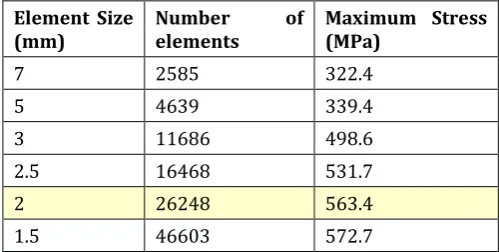
5. CONVERGENCE STUDY
Chart -1: Convergence study
[image:6.595.307.557.570.696.2]The number of elements where the Maximum stress results almost converge is approximately 26000 [11]. Hence the corresponding element size is approximately 2 mm.
Table -2: Convergence Study with chosen element size
Element Size
(mm) Number elements of Maximum Stress (MPa)
7 2585 322.4
5 4639 339.4
3 11686 498.6
2.5 16468 531.7
2 26248 563.4
1.5 46603 572.7
The Analysis for all the load cases was done on the A-Frame with a mesh size of 2 mm.
9(vi) - Pitching load case
© 2018, IRJET | Impact Factor value: 6.171 | ISO 9001:2008 Certified Journal | Page 1374
6. RESULTS AND DISCUSSION
[image:7.595.306.562.121.561.2]The results for the different load cases are found to lie above the typical FOS of 1.5. The Rolling load case is found to be having a major effect on the A-Frame with a marginal FOS of 1.518 because of Helicopter structures strength to weight ratio. The Natural frequency of the A-Frame didn't match that of the rotor's natural frequency. This meant that the structure was not affected by Resonance. Hence the analysis found that the design was safe.
Table -3: Results of Different Load Cases
Load Case Stress (MPa)
Displacem ent(mm)
Factor of Safety
Conclusio n
Lift 438.1 9.547 1.803 Safe
Torque 3.225 X 10⁻² 6.639 X 10⁻⁴ 2.4 X
104 Safe
Landing 79.67 1.730 9.916 Safe
Rolling
(LH) 520.3 12.300 1.518 Safe
Rolling
(RH) 90.46 2.220 8.733 Safe
[image:7.595.34.295.224.404.2]Pitching 163.3 3.872 4.838 Safe
Table -4: Results of Natural Frequency Analysis
Load Case
Range of Frequenc y of Rotor (Hz)
Natural Frequency of A-Frame in different modes of vibration (Hz)
Conclusi on
Mode
1 3.333-5.883 4.129 X 10² Safe Mode
2 3.333-5.883 1.598 X 10³ Safe Mode
3 3.333-5.883 7.050 X 10³ Safe Mode
4 3.333-5.883 1.001 X 10⁴ Safe Mode
5 3.333-5.883 1.931 X 10⁴ Safe Mode
6 3.333-5.883 3.935 X 10⁴ Safe
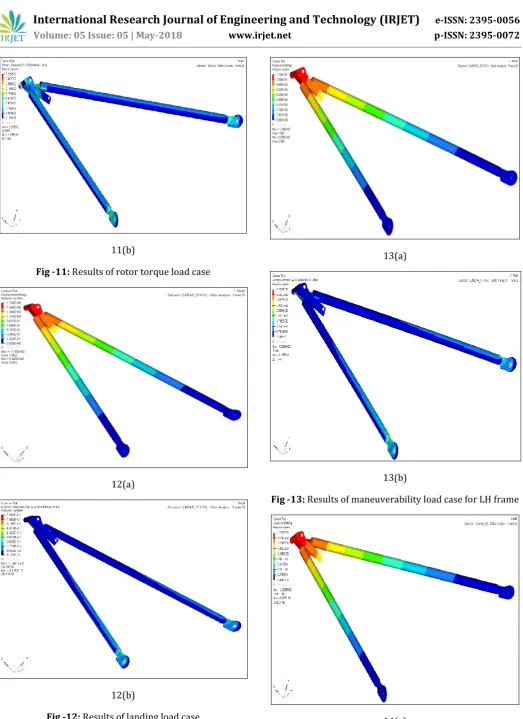
The results of Displacement (a) and Maximum Von-Mises stress (b) for different load cases are as shown from Fig -10 to Fig -15. Pseudo-stresses are not considered for the study [12].
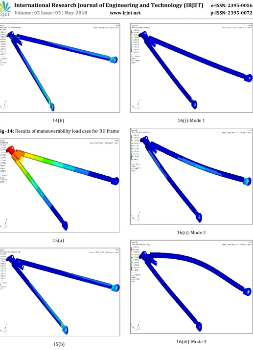
The results of natural frequency analysis are shown as in Fig -15. The different modes of natural frequency are shown in the Fig 16(i) to 16(vi).
10(a)
10 (b)
Fig -10: Results of lift load case
[image:7.595.35.287.451.672.2]© 2018, IRJET | Impact Factor value: 6.171 | ISO 9001:2008 Certified Journal | Page 1375 11(b)
Fig -11: Results of rotor torque load case
12(a)
[image:8.595.38.562.24.744.2]12(b)
Fig -12: Results of landing load case
13(a)
13(b)
Fig -13: Results of maneuverability load case for LH frame
© 2018, IRJET | Impact Factor value: 6.171 | ISO 9001:2008 Certified Journal | Page 1376 14(b)
Fig -14: Results of maneuverability load case for RH frame
15(a)
15(b)
Fig -15: Results of pitching load case
16(i)-Mode 1
16(ii)-Mode 2
© 2018, IRJET | Impact Factor value: 6.171 | ISO 9001:2008 Certified Journal | Page 1377 16(iv)-Mode 4
16(v)-Mode 5
[image:10.595.36.307.39.783.2]16(vi)-Mode 6
Fig -16: Different modes of vibration
7. CONCLUSIONS
In the present work, a detailed study is done on the A-Frame for critical load conditions. Also the load cases which would act on the A-Frame were determined and presented in a detailed way with reference. Convergence Study was also conducted by taking different element sizes and analysing for stress and choosing the correct element size by considering the averaging stress line.
The load cases acting on the A-Frame i.e., Lift Load, Rotor Torque, Landing Load, Maneuverability and Pitching were acting on the A-Frame at different angles and directions which was considered. Also the natural frequency analysis was considered for analysis which tends to show that the natural frequency of the A-Frame does not match with the Natural frequency of the rotor.
Also it is found that for the Light utility helicopter designed, the maximum roll angle possible without possible failure of the component was about 21o, beyond which any further change would lead to a large force acting on one of the links leading to the failure of the component. Overall, the Component was found to be safe and within the specified limits of yield stress.
8. REFERENCES
[1] Benjamin Boudon, Francois Malburet, Jean-Claude
Carmona, Georges Tod - "Modelling MGB-fuselage joint on helicopter with an energetic approach 'multi-bond graph'", June 2013.
[2] F. B. Gustafson and Almer D. Crim, "Flight measurements
and analysis of helicopter normal load factors in manoeuvre's", NACA Technical note-2990, August 1953.
[3] Frederick William Stellar D - "An investigation of aircraft
maneuverability and agility", AD-A224 587, May 1990.
[4] Prof. Amarnath.V. Hegne, Prof. Preeti. Hegne, "Design and
power transmission of advanced light helicopter", International Journal of Engineering Research and Applications (IJERA), ISSN: 2248-9622, Vol. 3, Issue 4, Jul-Aug 2013, pp.219-223.
[5] http://www.heli-chair.com/aerodynamics_101.html- an
article on how to calculate thrust loads.
[6] James A. Crabtree, Chief Weight Engineer and Asst. Chief
Design Engineer, Hughes Tool Co., Aircraft Div, "Weight estimation for helicopter design analysis", Technical Paper No. 177, The Society of Aeronautical Weight Engineers.
[7] http://www.aerospaceweb.org/question/performance/
q0146.shtml- Article on Bank angle and g force.
[8] Raghavendra Prasad, Graduate Student, Abhishek,
© 2018, IRJET | Impact Factor value: 6.171 | ISO 9001:2008 Certified Journal | Page 1378 Engineering, Indian Institute of Technology, Kanpur,
India, "Development and validation of inverse flight dynamics simulation for helicopter manoeuvre".
[9] Alfred Gessow and Garry C. Myers, Jr. Langley Memorial
Aeronautical Laboratory, Langley Field, VA, "Flight tests of a helicopter in autorotation, including a comparison with theory"
[10] Prof. E.G. Tulapurkara, Dept. of Aerospace Engg., Indian
Institute of Technology, Madras, "Flight dynamics-1, performance analysis V-maneuvers", Chapter-9, Lecture 28.
[11]
https://knowledge.autodesk.com/support/simulation- mechanical/learn-explore/caas/sfdcarticles/How-to-Perform-a-Mesh-Convergence-Study.html
[12]