© 2018, IRJET | Impact Factor value: 7.211 | ISO 9001:2008 Certified Journal | Page 2130
DESIGN AND IMPLEMENTATION OF RATION DISTRIBUTION SYSTEM TO
STOP THE CORRUPTION USING AVR
Rita Ravindra Chaudhari
11
M.TECH student, Electronics and Telecommunication, Government College of Engineering, Jalgaon, Maharashtra,
India
---***---Abstract -Public distribution system (PDS) is one of theimportant provisioning systems in Our Indian country. This PDS is recognized by the Government of India subordinate
Ministry of Consumer Affairs, Food and Public Distribution. The fair price shops are mainly used to distribute the goods with low cost or free of cost. In the proposed system, the concept is to replace the manual work in public distribution system. The ration distribution system is automated by using embedded system technology, which is similar to the ATM. This automated ration system replaces the conventional ration card system by smart card. In addition, the finger print module is placed in the system in order to check the correct user access. If the user is correct user, the next process takes place. For the efficient operation and economic constraints of the system, the power supply unit is fully made alternate to solar power. The future work on this system is to attach a weighing system so that weighing of ration should be accurate. We can also develop an online database for large number of users and receive an acknowledgement for the delivered message.
Key Words: GSM, RFID, Biometrics(R305), Public Distribution System, Controller, Mechanical Part
1. INTRODUCTION
Ration distribution an initiative by the Government of India under Ministry of Consumer Affairs, Food and Public Distribution intend for the distribution of commodities to destitute at fair price. In the projected system we use RFID Technology. One of its parts, a RFID tags hold a unique ID is issued to all the BPL card bearers. Here RFID tag (Smart Card) and the biometrics serves the purpose of authentication. Information and the fingerprint impression of the head of the family and one of the family members are cached in the centralized database whose access is only legitimized for a government authority. The first of the two authentication steps needs the beneficiary to swipe the Smart Card against RFID Reader installed at the FPS and the second step towards an authentication is that he/she should scan the fingerprint of his/her thumb against biometric. On matching his/her fingerprint with the id stored in the device, an appropriate fingerprint id interface with database to checks for valid beneficiary’s information.
Once authenticated, updated information is obtained by automated ration system concerning the existing subsidies for the beneficiary onto the main interface. A beneficiary is permitted to take only those subsidies on products apportioned to him/her by government according to the
available database inventory. After every transaction made by the beneficiary, centralized database is immediately updated and he/she will be sent a SMS (Short Message Service) specifying the quantity of commodity bought by him/her. With implementation of the projected system prime issues like bribery, uneven distribution and other difficulties faced by beneficiary can be terminated
2. RATION DISTRIBUTION SYSTEM- BACKGROUND
Mr. Abhijeet Chimgave et.al.[1], this project proposes a transparent and highly scalable Ration Distribution system with authentication for Ration Card Holder. Every time ration is collected by the family is logged into the RFID (smart)card.
Bharati Chilad et.al.[2], the proposed system replaces the manual work in FPS. The prime objective of the designed system is the automation of FPS to provide transparency. The proposed automatic FPS for public distribution system is based on RFID technology and biometric authentication technology that replaces conventional ration cards.
Kashinath Wakade et.al.[3], this paper implements a simple PDA device (personal data assistant) with RFID tag used as an e-ration card in place of a conventional ration card.
M.S.Manivannan et.al.[4], the project proposes an approach to automate all the above said manual jobs and the whole thing from data entry to weighing to hammering is prepared by machines and the people have no hand in that.
Mohit Agarwal et.al.[5], developed a smart ration card using Radio Frequency Identification (RFID) technique to prevent the ration forgery as there are chances that the shopkeeper may sell the material to someone else and take the profit and put some false amount in their records.
Rajesh C.Pingle, P.B.Borole[8] “Automatic Rationing for Public Distribution System (PDS) using RFID and GSM Module to Prevent Irregularities”, In this automated system conventional ration card is replaced by smartcard in which all the details about users are provided including their AADHAR (social security) number which is used for user authentication.
2.1 Existing System
© 2018, IRJET | Impact Factor value: 7.211 | ISO 9001:2008 Certified Journal | Page 2131 and they will put the sign in the ratio card depends on the
materials. Then they will issue the materials through weighting system with help of human. But in this system having two draw backs, first one is weight of the material may be inaccurate due to human mistakes and secondly, if not buy the materials at the end of the month, they will sale to others without any intimation to the government and customers.
The present PDS works in a multiple level where the responsibilities are shared between center and state. The task of procuring or buying food grains such as wheat and rice at minimal cost is the responsibilities of center Allocation of the grains to each state in carried out by center.While the state government are responsible for the identification of household eligible to avail the facilities. The process runs as follows, the grains are transported by the center to every state’s central depot, after which the allocated food grains are delivered to respective FPS through state government. Finally FPS being the end point sells the entitled commodities to beneficiaries.
In the existing system, tasks like product distribution, Ration Card entry, product weighing and delivery of the product are carried out manually by FPS agent. However a present system has diverse drawbacks involved, developing irregularities in the system. Some of the irregularities include replacing actual products dispensed by the government with meager quality products and supplying the same for the beneficiaries, diverting food grains to open market to make profit, false entries in the stock registers that FPS agent needs to maintain and false announcement of deceit in food grains.
2.2 Designed System
In this system , the concept is to replace the manual work in public distribution system. The ration distribution system is automated by using embedded system technology, which is similar to the ATM. This automated ration system
replaces the conventional ration card system by smart card. In addition, the finger print smart card is placed in the
machine in order to check the correct user access. If the user is correct user, the next process takes place. As soon as the input is given, the products are obtained from the automated ration shop and the amount is taken from account of the particular person. The embedded controller is preprogrammed in such a way to perform the similar operations. In this automated ration shop government have control over all transaction that occurs in ration shop. In order to involve government in the process, the proposed ration shop system is connected to the government database via GSM modules, which further sends the up-to-date information to the government and the consumer. For the efficient operation and economic constraints of the system, the power supply unit is fully made alternate to solar power.
3. SYSTEM DESIGN
3.1 Functional Requirements
In this system there are some functional requirements for beneficiaries and server side or food department. The functional requirements are as follow:
3.1.1 Functional Requirements for Beneficiaries Beneficiary and his/her family member’s details are
stored and RFID tag is assigned to the beneficiary.
Fingerprints of beneficiaries and family members are captured and stored to obtain the identity.
Verification of card is done using RFID Reader installed at the center and once verified the system will verify the fingerprint of the beneficiary or his/her family member.
3.1.2 Functional Requirements for Server Side (Food Department)
Stocks are updated by food department. They maintain the incoming stock, total distribution of stocks and also the remaining stock.
Reports of inventory are updated on the server side.
The system also has a shopping cart for allowing the beneficiaries to shop and do the payments.
3.2 DESIGNED APPROACH A) Block Diagram
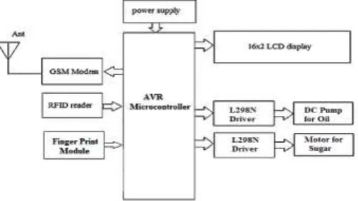
[image:2.595.310.564.589.732.2]This ration distribution system mostly performed to reduce the corruption and reduce the wastage of time. Because in our system the goods are distributed automatically without any manpower. Figure 1 explains the basic module of automatic materials distribution and stock maintenance based on smart ration card technology. This system consists of the AVR Microcontroller, smart card, fingerprint module, motor driver, LCD and GSM. The proposed system expresses sharing of grains as well as liquids.
© 2018, IRJET | Impact Factor value: 7.211 | ISO 9001:2008 Certified Journal | Page 2132 The block diagram of an Automatic Ration Materials
Distribution Based on GSM and RFID Technology is shown in Figure 1. This system consists of various parts such as RFID, Finger print module, GSM, microcontroller, motor driver, solenoid control circuits and AVR microcontroller.
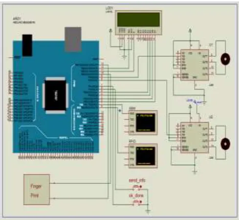
B) Circuit Diagram
[image:3.595.39.284.227.452.2]The circuit diagram of the designed system as shown in figure In this, the interfacing of controller(ATmega2560, Arduino board)with LCD display, two DC motor drives, GSM module, RFID reader, Fingerprint module, Toggle switches.
Fig. 2: Block Diagram of Designed System
Working of proposed System
In this designed system when the ration of the peoples is send by govt. Then system will get activated in the ration shops, the particular user gets SMS on his mobile number about the ration send at PDS shops.
Every user is provided by the smart card, the users have to come with smart card at the PDS shop.
First he will scan the smart card by RFID scanner then the thumb impression will be verified.
If the user is get validate the ration distribution system gets activated, on LCD display step by step the ration names is appears according to that the user will conduct his ration.
At the end, the PDS authority gets an acknowledgement through SMS regarding ration.
3. PERFORMANCE ANALYSIS AND RESULT
In system performance, when the proposed system is implementing in real world, Beneficiary can check the availability of commodities online, by viewing the website. It
contains the information of various ration shops available nearby and can also check the commodities available in the respective Ration shop. The beneficiary can also check the details of the FPS available nearby. Admin can add new shop, get detail of each shop, delete shop, and edit shop stock. And also upgrade the user profiles.
The website contains various fields like:
“About the Project”- briefly describes the project.
“Features of Project”- gives various aspects with respect to project.
“Contact us”- for any query regarding the Ration system.
ANALYSIS OF DESIGNED PROTOTYPE WITH STANDARD DEVIATION
To analyze the system performance some users are considered and number of trials executions are carried out and the results are summarized in below fig.
Sr. No.
Users No. of Successful Trials (out of 10) Efficiency
SMS Unit
Authentication Unit
Ration Distribution Mechanism
RFID Fingerprint Rice Oil
1 ID-1 10 10 10 10 10
98.8%
2 ID-2 10 9 10 10 10
3 ID-3 9 10 10 10 10
4 ID-4 10 10 9 10 10
5 ID-5 10 10 10 10 10
[image:3.595.294.568.334.505.2]SD 0.40 0.40 0.40 0 0
Fig 3: Test Result Analysis Table
The number of successful trials is carried out for each section in the designed prototype and for each subject.
Standard Deviation of a system provides an indication of how far the individual responses vary or “deviate” from the mean. For this system the value of standard deviation ranges from 0 to 0.40. Standard deviation should have small value for desired performance. Here deviation is small. In all five types of analysis some subjects are unable to perform all operation successfully due to illiteracy of subjects to handling the system. Also some unsuccessful events are due to controlling operations in the system. Even though all types of subjects can handle system in full fledge manner after certain trials. This system will surely help to people without corruption in ration distribution system at fair price shop.
4. RESULTS AND DISCUSSION
© 2018, IRJET | Impact Factor value: 7.211 | ISO 9001:2008 Certified Journal | Page 2133 liquid or solid material, which is used for Ration materials
distribution in ration shops. Initially In this proposed system when the ration of the peoples is send by govt. Then system will get activated in the ration shops, the particular user gets SMS on his mobile number about the ration send at PDS shops. Everyone will be provided an RFID or smart Card, instead of a ration card. If the customer needs to get any ration material, the user has to show the ration RFID tag card to the RFID reader Kit, the reader that is incorporated with the project kit will recognize the RFID numbers show by the user. Each user will have a unique number, which is not visible to the user.This recognized RFID number will be given to a microcontroller, which compared the input number with the database. Before starting the system, the unique RFID number of the ration user will be programmed in the controller. Therefore the controller will recognize the data coming from RFID by comparing with the database. After this the thumb impression will be verified for the correct user authentication.
[image:4.595.309.571.76.281.2]Comparative study of existing and proposed system:
Fig- 4: Comparative study of existing and proposed system
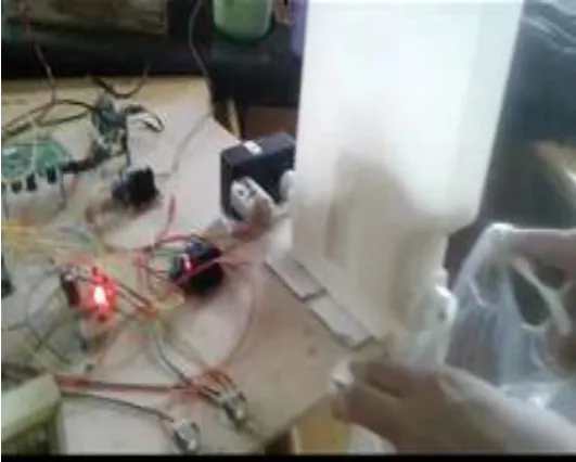
4.1 Prototype System Mode
[image:4.595.29.267.347.467.2]Fig -4: Prototype Model of proposed System
[image:4.595.308.574.407.620.2]Fig -5: Identification of Customer
Figure 5 shows identification of customer using fingerprint module. After Reading of RFID Tag now system is ready to authenticate the fingerprint registered by card holder (user) and this process of authentication is done with the aid of fingerprint scanner once fingerprint is matched with the registered fingerprint then ration distribution system goes activated.
Fig - 6: Rice Distribution
Above fig.5 shows the ration distribution mechanism, It shows the distribution of rice. As Ration distribution system is activated after process of authentication then allocated ration material is distribute by system with desired quantity and controlled by arduino controller connected to motor driver as well as DC motor.
1 Ration sheets are
used RFID tag act as ration card 2 Ration materials
distributed manually Ration distributed materials automatically using automated system 3 Inaccurate Accurate
[image:4.595.40.283.521.719.2]© 2018, IRJET | Impact Factor value: 7.211 | ISO 9001:2008 Certified Journal | Page 2134 Fig -7: Oil Distribution
After the rice distribution there is another mechanism for oil distribution which is shown in Figure 4.15. For oil there is a special mechanism connected with DC submersible pump in oil tank and that mechanism is also controlled by controller and motor driver to distribute desired quantity send to GSM. send the text SMS to the PDS authority on the ration item, he or she purchased. Table 4.6 shows the comparative study of existing and proposed system.4.1 Performance Analysis of Multiplier
The system is based on 4:2 compressor and Wallace compressor techniques of Vedic multiplier. These two techniques are used in design the structure of 16 and 32-bit multiplier. Results of software implementation was observed and compared by implementing these multiplier structures on Xilinx FPGA platform. Analysis of different multipliers was observed with the help of design summary overview which allows a quick access to design overview information and synthesis reports. Performance analysis of different multiplier was done based on various parameters.
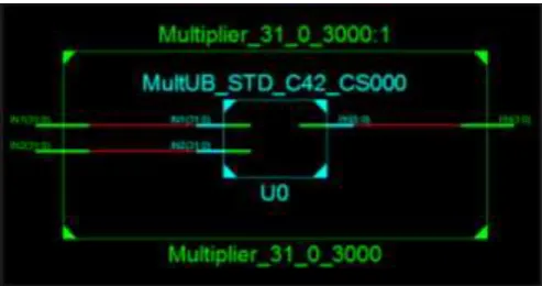
RTL schematic for 32x32 Vedic multiplier with 4:2 compressor is as shown in figure 7.There are three ports namely, data input (IN1), data input (IN2), data output (P), all signals are active high.
[image:5.595.312.557.232.399.2]The representation of three ports:
Fig -7: Schematic for 4:2 Compressor Vedic Multipliers
Analysis of 32X32 Multiplier with 4:2 Compressors
Analysis is carried out by designing 32-bit multiplier using 4:2 compressor multiplier architecture in Xilinx ISE Simulator. Slice flip flops are resources on the FPGA that can perform logic functions. Logic resources are grouped in slices to create configurable logic blocks. A slice contains a set number of LUTs, flip-flops and multiplexers. An LUT is a collection of logic gates hard-wired on the FPGA. LUTs store a predefined list of outputs for every combination of inputs and provide a fast way to retrieve the output of a logic operation.
Fig – 8: Area Comparisons of 4:2 Compressor 32-bit Vedic Multipliers
Table 4.1 Resource Utilization for 32-Bit 4:2 Compressor Vedic Multiplier
Parameters
Resources
Used Available Utilization
(%)
Number of Slices
LUTs(A) 2330 12480 18 Number of LUT’S
Flip-flops Pair used(B) 2330 12480 18 Number used as
logic(C) 2330 12480 18 Number of bonded
IOBs(D) 128 172 74
[image:5.595.38.285.610.740.2]© 2018, IRJET | Impact Factor value: 7.211 | ISO 9001:2008 Certified Journal | Page 2135 The schematic for 32x32 Vedic multiplier with
Wallace compressor is as shown in figure 9.There are Three ports namely, data input (IN1), data input (IN2), data output
[image:6.595.309.555.74.321.2](P), all signals are active high.
Fig-9: Schematic for Wallace Compressor Vedic Multiplier
Analysis of 32X32 Multiplier with Wallace Compressor
Analysis is carried out by designing 32-bit multiplier using Wallace compressor multiplier architecture in Xilinx ISE simulator. Slice flip flops are resources on the FPGA that can perform logic functions. Logic resources are grouped in slices to create configurable logic blocks. A slice contains a set number of LUTs, flip-flops and multiplexers. An LUT is a collection of logic gates hard-wired on the FPGA. LUTs store a predefined list of outputs for every combination of inputs and provide a fast way to retrieve the output of a logic operation.
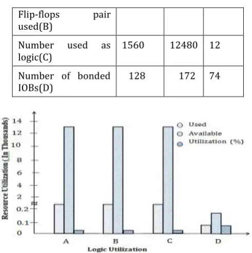
Resource utilization for implementation of Wallace compressor Vedic multipliers enlisted in Table 4.2 Based on the percentage of resources utilized it is quite possible to estimate the area of the design. This table explained about available and used resources with percentage of utilization. For example 12480 available resources while 1560 used resource so percentage utilization found to be 12%, the same procedure for remaining parameters. It also expressed the complexity of the design. Figure 10 represents the Area comparisons of Wallace compressor 32-bit Vedic multipliers.
Table 4.2 Resource Utilization for 32-Bit Wallace Compressor Vedic Multiplier
Parameters
Resources
Used Available Utilization (%)
Number of Slice
LUT’s(A) 1560 12480 12 Number of LUT’s 1560 12480 12
Flip-flops pair used(B)
Number used as
logic(C) 1560 12480 12 Number of bonded
IOBs(D) 128 172 74
Fig – 10: Area Comparisons of Wallace Compressor 32-Bit Vedic Multipliers
4.2 Comparative Analysis
The three different multiplications 8, 16 and 32-bit perform by using 4:2 compressors and Wallace compressor Vedic multiplier is compared for time delay and area obtained from resource utilization.
4.2.1 Comparative Analysis for Resource Utilization of Different Multiplier
Table 4.3 and 4.4 provides comparison of resource utilization using three multipliers required in designing of 4:2 Compressor and Wallace Compressor respectively. The maximum path delay for 8-bit multiplier observed to be 10ns while for 16-bit and 32-bit bit multiplier it observed to be 16 and 18ns respectively. These conclude that as number of bits increases, path delay reduces. Hence at higher bit multiplier get minimum path delay compared to lower bit multiplier. After referring previous algorithm it is observed that our propose algorithm requires minimum path delay.
Table 4.3: Comparative Analysis for Resource Utilization for 4:2 Compressor Multipliers
Parameters
Multiplier
8-Bit 16-Bit 32-Bit
Number used as logic 124 659 2330 Number of Slice LUTs 124 659 2330 Number of IOs 32 64 128 Maximum path
[image:6.595.43.283.138.309.2]© 2018, IRJET | Impact Factor value: 7.211 | ISO 9001:2008 Certified Journal | Page 2136 Table 4.4: Comparative Analysis for Resource Utilization
for Wallace Multiplier
Parameters
Multiplier
8 Bit 16 Bit 32 Bit
Number used as
logic 98.0 432.0 1560.0 Number of Slice
LUTs 98.0 432.0 1560.0 Number of IOs 32.0 64.0 128.0 Maximum path
delay(ns) 10.9 15.8 18.8
Delay is the main constituent factor in any design that decides the performance of the system. For efficient system delay should as minimum as possible. Table 4.5 provides the comparative analysis of time for 4:2 compressor multiplier and Wallace tree Multiplier. It indicate that 4:2 compressor Vedic multipliers requires more time for operation due to more number of gates that of Wallace tree Vedic multiplier.
The designs of 32x32 bits Vedic multiplier have been design on Xilinx 13.2(vertex 7). The computation delay for 32x32 bits 4:2 compressor Vedic multiplier was 15.83 ns and for 32x32 bits Wallace tree Vedic multiplier were 12.71ns. It is therefore seen that the Wallace tree Vedic multipliers are faster than the 4:2 compressor. For vertex 5 the computation delay for 32x32 bits 4:2 compressor Vedic multiplier was 18.71ns and for 32x32 bits Wallace tree Vedic multiplier were 18.80ns. The Figure 11 shows comparative analyses for 4:2 and Wallace compressor 32-bit multiplier.
Fig -11: Comparative Analyses for 4:2 and Wallace Compressor 32-Bit Multiplier
Table 4.5: Comparative Analysis for 4:2 Compressor and Wallace Tree 32-Bit Multiplier
Parameters
32-Bit 4:2 Compressor Multiplier
32-Bit Wallace Compressor Multiplier
Number of Slices LUTs 2374.00 1560.00 Total Number of Path 15675988.00 7807402.00 Total Time Delay(ns) 18.71 18.80 Total Memory use(KB) 524600.00 531768.00
4.3 Experimental Result
Design of Vedic multiplier by using 4:2 compressor and Wallace compressor with their experimental result as follows.
4.3.1 Result of 4:2 Compressor Vedic Multipliers
The 32x32 bits Vedic multiplier has been design using Xilinx 13.2. The timing waveform of 16X16 bit,4:2 compressor Vedic multiplier is as shown in figure 12 which represent output obtained from various input vector provided in the test bench program during simulation. It has two inputs in1 and in2 and one outputs p. Figure 12 shows Timing Waveform for 4:2 compressor Vedic multipliers
Fig-12: Timing Waveform for 4:2 compressor Vedic multipliers
4.3.2 Result of Wallace Compressor Vedic Multiplier
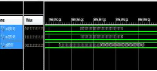
The 32x32 bits Vedic multiplier has been Design using Xilinx 13.2. The timing waveform of 32X32 bit Wallace compressor Vedic multiplier is as shown in figure 13 which represent output obtained from various input vector provided in the test bench program during simulation. It has two inputs in1 and in2 and one outputs p. The figure 13 shows Timing Waveform for 32-bit Wallace Compressor Vedic Multiplier
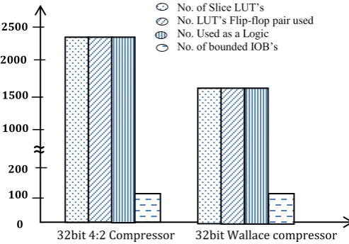
0 100 200 2500
2000
1500
1000
No. of Slice LUT’s
No. LUT’s Flip-flop pair used No. Used as a Logic No. of bounded IOB’s
32bit 4:2 Compressor 32bit Wallace compressor
[image:7.595.45.292.512.684.2]© 2018, IRJET | Impact Factor value: 7.211 | ISO 9001:2008 Certified Journal | Page 2137 Fig -13: Timing Waveform for 32-Bit Wallace Compressor
Vedic Multiplier
5. CONCLUSION
In this paper, a modified compressor based multiplier was introduced that uses Vedic mathematics to get a high speed multiplication operation.
The designs of 16x16 bits and 32x32 bits Vedic multiplier have been Design on Xilinx 13.2(vertex 7). The computation delay for 8x8 bits multiplier was 5.02ns, the computation delay for 16x16 bits multiplier was 9.09ns. The computation delay for 32x32 bits 4:2 compressor Vedic multiplier was 15.8 ns and for 32x32 bits Wallace tree Vedic multiplier was 12.7ns. It is therefore seen that the Wallace tree Vedic multiplier observed to be faster than the 4:2 compressor Vedic multiplier. For vertex 5 the computation delay for 32x32 bits 4:2 compressor Vedic multiplier was 18.71ns and for 32x32 bits Wallace tree Vedic multiplier were 18.80ns.
Urdhvatiryakbhyam, Nikhilam and Anurupye sutras used in proposed algorithm results in minimum delay, power and hardware requirements for multiplication of numbers. Use of a compressor observed to be easy processing element with less complexity which used in digital logic design for compression of data.
High speed realization multiplier with less area consumption has become more demanding over the years. Moreover, compression processing to multiplier being applied to increase the effective throughput. Delay and area observed to be constituent factors in VLSI design that limits the performance of any processor and multiplier which tends to be crucial elements that decides requirement of these factors. Working on less time delay consider as very essential requirement in many applications.
REFERENCES
[1] M. Ramalatha, K. Deena Dayalan, S. Deborah Priya, “High Speed Energy Efficient ALU Design using Vedic Multiplication Techniques,” Advances in Computational Tools for Engineering Applications, 2009, IEEE Proc., pp. 600-603
[2] H. Singh Dhillon and A. Mitra, “A Reduced-Bit Multiplication Algorithm for Digital Arithmetic’s”,
International Journal of Computational and Mathematical Sciences 2; 2008.
[3] Jagadguru Swami Sri Bharati Krishna Tirthji Maharaja, “Vedic Mathematics”, Motilal Banarsidas, Varanasi, India, 1986.
[4] H. Thapliyal, S. Kotiyal and M. Srinivas, “Design and Analysis of A Novel Parallel Square and Cube Architecture Based on Ancient Indian Vedic Mathematics”, Centre for VLSI and Embedded System Technologies, International Institute of Information Technology, Hyderabad, 500019, India, 2005.
[5] H. Thapliyal “VLSI Implementation of RSA Encryption System Using Ancient Indian Vedic Mathematics”,
Centre for VLSI and Embedded System Technologies, International Institute of Information Technology, Hyderabad-500019, and India.
[6] A. Kumar and D. Kumar, “Hardware Implementation of 16*16 bit Multiplier and Square using Vedic Mathematics”, Design Engineer, CDAC, Mohali.
[7] N. Rajasekhar and T. Shanmuganantham ,“A Modified novel Compressor based urdhwa Tiryakbhyam Multiplier”, International Conference on Computer Communication and Informatics (ICCCI),03rd May2014,
Coimbatore, India.
[8] “Spartan-3E FPGA Starter Kit Board User Guide”, UG230
(v1.1) June 20, 2008.