© 2018, IRJET | Impact Factor value: 6.171 | ISO 9001:2008 Certified Journal | Page 2775
Hardware Implementation of VLC using CMOS Camera
1Shriram M. Madavi, 2 R. R. Harne
1M. Tech Scholar, Dept. of Electronics, GCOE Amravati [MH], India
2Assistant Professor, Dept. of Electronics, GCOE Amravati [MH], India
---***---Abstract
Recently, visible light communication (VLC)technology has been gaining attention in both academia and industry. It is secure communication when compared with other wireless communication using radio frequency. And it is attractive if mobile phone camera can be used as receiver. The Radio Frequency (RF) communication suffers from interference and high latency issues. Along with this, RF communication requires a separate setup for transmission and reception of RF waves. Overcoming the above limitations, Visible Light Communication (VLC) is a preferred communication technique because of its high bandwidth and immunity to interference from electromagnetic sources. The revolution in the field of solid state lighting leads to the replacement of florescent lamps by Light Emitting Diodes (LEDs) which further motivates the usage of VLC. The information is captured in the camera in the form of light and dark bands which are then decoded by the MATLAB and the received message is displayed. By exploiting the rolling shutter effect of CMOS sensors, a data rate much higher than the camera frame rate is achieved.
Key Words: Visible Light Communication, Mobile phone camera, Digital image processing, Rolling shutter…
1.INTRODUCTION
Visible light communication is very good attractive to radio frequency communication as it finds a wide range of applications in indoor communication compared with radio frequency communications,The explosion in mobile devices usage over the last decade has led to the ever increasing usage of the limited and expensive radio spectrum. One of the key candidates to solve the so-called capacity crunch in certain applications is the visible light communications (VLC), which potentially offers 10,000 times more bandwidth capacity than the RF based technologies. VLC has many advantages such as large amount of bandwidth, more secure and it has visible light spectrum available for use which is not regulated. Also, visible light communication is not harmful to human body. Over the last decade, mobile with embedded cameras have become common technology. The majority of new generation smartphone have built-in CMOS cameras which provides an ability to capture image and videos. Therefore, it is highly desirable to use these already existing mobile phone image sensor as the VLC receiver. Over the last decade, smartphones have penetrated in almost everyone’s daily life. As most smartphones have embedded cameras, providing the ability to capture pictures and videos, they can be utilized as VLC receivers. On the
other hand, LEDs are widely used in vehicle lighting and traffic lights. They can be easily modified to become VLC transmitters. The information is captured in the form of light and dark strips through the direct line of site without reflected surface. Then extracts the grayscale information transmitted to the computer. Afterward information is generated by the MATLAB and then it is decoded through digital image processing. This method continuously receives the information and decode into steam data is referred as VLC (visible light communication).
2. RELATED WORK
Visible light communication is becoming an attractive choice for next-generation wireless technology. Nowadays researchers are working on development of visible light communication systems.
In [1], VLC system based on a modified version of the classical orthogonal frequency division multiplexing. Modulation techniques also present a hardware prototype for short range broadcasting using a white LED lamp. While LED bulbs clear advantages over conventional incandescent and fluorescent bulbs, which makes them a strong candidate for future illumination equipment. European Commission has decided recently to prohibit the sale of particularly energy intensive lamps foe household use in series stages up to 2016 and as soon as high efficient white LED bulbs are manufactured cheap enough to overtake currently favored compact fluorescent bulbs. a communication network infrastructure will be available.
In [2], LED lights are becoming widely used for homes and offices for their luminous efficacy improvement. Visible light communication (VLC) is a new way of wireless communication using visible light. Typical transmitters used for visible light communication are visible light LEDs and receivers are photodiodes and image sensors. We present new applications which will be made possible by visible light communication technology. Location-based services are considered to be especially suitable for visible light communication applications.
© 2018, IRJET | Impact Factor value: 6.171 | ISO 9001:2008 Certified Journal | Page 2776
In [4], the camera image sensor is explained. As VLC receiver is challenging since data rate limited by the frame rate as well as uneven light exposure, rolling shutter effects of the image sensor can use to increase the data rates.
In [5], researchers present the way to extend the VLC transmission distance and mitigate the influence of the background noise. Also, using histogram equalization and Sobel filter, enhancement in the VLC signal performance is demonstrated. In this work, demonstrated a VLC link using CMOS mobile phone camera as Rx. By rolling shutter effect of the CMOS sensor, the VLC data rate can be significantly enhanced.
In [6], researchers present the rolling shutter distortion correction. Here, rolling shutter distortion is corrected using only captured images by means of image processing. A global motion vector (GMV) between two successive image frames is firstly estimated, then the line motion vector for each line (LMV) is determined by smoothly interpolating GMVs estimated from several successive frames.
In [7], MATLAB by default is a single threaded application. so the single thread uses just one core irrespective of how many cores are available to run any simulation. Data analysis and visualization tool which has been designed with powerful support for matrices and matrix operations.
In [8]In this paper we present a new systolic architecture for two basic mathematical morphology operations. Mathematical morphology has been proven to be a very useful tool for applications such as image restoration, image skeletonization, pattern recognition, machine vision etc. The advantages of our design stem from the fact that it has pipeline period a = 1, requires simple communications, and is exploiting the simplicity of the morphological operations to make it possible to implement a linear target machine without using multi projection, although the starting algorithm is a generalized 2-dimensional convolution
2.1 Visible Light Communication
The Radio Frequency communication suffers from interference and high latency issues. In addition to this, it requires a separate setup for transmission and reception of RF waves. These limitations can be overcome by using Visible Light Communication (VLC) technique because of its high bandwidth and immunity to interference from electromagnetic sources. The application of visible light communication systems is to transmit data while maintaining efficient and good quality illumination service. It uses visible light spectrum i.e., between 400 and 800 MHz. It is considered as the subset of optical wireless communication technology. Light Emitting Diodes (LEDs) are semiconductor devices similar to silicon chips. LEDs can be switch at very high speeds that were not possible with earlier light bulb technologies such as fluorescent and incandescent lamps. The rapid adoption of LED light bulbs
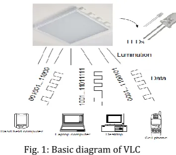
[image:2.595.351.529.162.319.2]has created a massive opportunity for VLC. The signals in the 380-780 nm wavelength interval of the electromagnetic spectrum are the light signals that can be detected by the human eye. It is possible to achieve illumination and data transfer simultaneously by means of LEDs that is the prominent lighting equipment lately.
Fig. 1: Basic diagram of VLC
By this way, both interior lighting of a room and data transfer will be achieved without the need of an additional communication system. This technology is given the name of Visual Light Communication.
2.2 VLC Spectrum
Visible light should be considered as the medium for wireless transmission because it has a few advantages over other standard wireless transmissions. The first reason to consider is visible light’s frequency spectrum bandwidth, which ranges from 430 THz to 750 THz. The bandwidth is much larger than the radio frequency bandwidth, which ranges from 3 kHz to 300 GHz. With a larger bandwidth it is possible to accommodate more users and potentially achieve higher transfer rates because each user can be given a larger portion of the bandwidth to transfer information.
Fig. 2: VLC spectrum
2.3 Mobile phone CMOS camera:
© 2018, IRJET | Impact Factor value: 6.171 | ISO 9001:2008 Certified Journal | Page 2777
triggered arrow-sequentially process known as rolling shutter. This effect allows us to transmit with data rates that far exceed the frame rate of the camera.
2.4 Digital Image Processing:
Digital image processing has become the most common form of image processing and generally, is used because it is not only the most versatile method, but also the cheapest. It uses computer algorithms to perform image processing on digital images. As a subcategory or field of digital signal processing, digital image processing has many advantages over image processing. It allows a much wider range of algorithms to be applied to the input data and can avoid problems, the build-up of noise and signal distortion during processing. Since images are defined digital image processing may be modeled in the form of multidimensional systems.
3. SYSTEM DEVELOPMENT
[image:3.595.309.558.401.625.2]Fig. 3 shows the basic block diagram of VLC experiment system. The light source is used as a transmitter, in visible light communication. White LED serves as a very good optimum transmitter. The transmitter consists of Field programmable gate array (FPGA), LED driver and LED lamp array with 15 LEDs. Firstly, an arbitrary binary waveform is generated by FPGA. The signal is transmitted to LED lamp which provides lighting LED lamp array is lightened up by the LED driven and transmits an ON-OFF keying signal.
Fig. 3: Block diagram of VLC
The receiver side consists of mobile phone CMOS sensor and computer. The modulated light is received by a mobile phone camera through direct line-of-site without reflected surfaces. The CMOS sensor of mobile phone has a resolution and frame rate of 640×480 and 30 frames per second respectively.
The camera captures the image of light and dark stripes and then digital image processing based on MATLAB is applied. The preview images are stored in a buffer of the mobile phone using the YUV format. The preview images are stored in a buffer of the mobile phone using the YUV format, the output of which is a matrix consisting of three components: The Y luminance and the U and V chrominance components. The first one contains the brightness information and the other two carry the chrominance information. Because the U and V components include only information about the colors of the image, they can be discarded from the decoding procedure. And the transformation of the grayscale is indicating by Y component, so it is the valid information for digital image processing.
4. EXPERIMENTAL RESULTS
In this paper, we are transmitting digits in binary form. It will convert into light and then transmitted to receiver side using visible light communication.
A Transmitter
[image:3.595.64.268.462.650.2]In this experiment, digits are transmitted in the form of binary. FPGA form string and micro PRO AVR is used to send digit which will convert into the binary form. It is displayed in the form of light. Fig. 4 shows the transmitting section.
Fig. 4: Transmitter using micro PRO AVR
© 2018, IRJET | Impact Factor value: 6.171 | ISO 9001:2008 Certified Journal | Page 2778
Fig. 5: Light display pattern B. Receiver
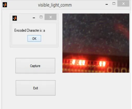
[image:4.595.41.286.81.304.2]In the receiver, captured image is given to MATLAB which will decode it using the concept of image morphology. Digits are decoded which are similar to the transmitted digits. These digits then used to display encoded character. Fig. 6 indicates receiver section using MATLAB when character ‘a’ is captured.
Fig. 6: Captured image
5. PERFORMANCE EVALUATION
In order to test performance of the VLC system, a CMOS camera is used as the receiver. The LED lamp array which consists of 10 small white LEDs are used as the transmitter. An arbitrary binary waveform is generated by FPGA and the duration of a logic 1 is 500us. Then, the LED lamp array is
[image:4.595.35.288.435.644.2]lightened up by the LED driver and transmits a 2000 Hz ON-OFF keying. The data rate of the transmitter is 2000bps. The system is evaluated by transmitting a binary sequence form the LED lamp array to the camera of CMOS and the received binary sequence is displayed in computer.
Table No. I Test Result of different distances
Sr. No. Distance Error Bit Error Rate(BER)
1. 10 cm 0/1 0 %
2. 20 cm 0/1 0 %
3. 30 cm 0/1 0 %
4. 40 cm 0/1 0 %
5. 45 cm 0/1 0 %
6. 48 cm 1/1 100 %
For different distances between CMOS Camera and LED lamp array 10 cm, 20 cm, 30 cm, 40 cm, 45 cm, 48 cm are tested respectively. As shown in Table I, when the distance of communication is relatively short, no bit error is observed. However, for larger distance, BER increases. This is because the difference between light intensity of dark and bright strips are too small for the decoder to distinguish as distance increases.
6. CONCLUSIONS
The potential of using visible light communication for data transmission to a CMOS camera is investigated in this paper. Digital image processing scheme for VLC using CMOS camera as receiver is proposed. In order to achieve this, different image processing methods such as grayscale conversion and morphological operation is used. Through image processing clear light and dark stripes and valid information is obtained. Bit Error Rate is calculated by measuring different distances between Light displayed by LEDs and CMOS Camera for various characters. It is concluded that Visible Light Communication is a function of this distance and is generally used for short range communication.
REFERENCES
[1] Digital image processing in LED visible light communications using mobile phone camera. IEEE 2016
[2] Liu Y, Chen H., Liang K., & Hsu C., Visible light communication using receiver of camera sensor and solar cell, IEEE Photonic journal 2016
[3] Haruyama S. Visible light communication using sustainable Led Lights// building Sustainable communities. IEEE 2013
© 2018, IRJET | Impact Factor value: 6.171 | ISO 9001:2008 Certified Journal | Page 2779
[5] Elgala H, Mesleh R, Hass H, Indoor broadcasting via white LEDs and OFDM IEEE Consumer Electronics 2009 55(3):1127-1134
[6] Liang C k, Peng Y C, Chen H. Rolling shutter Distortion correction[j]. Proceeding of SPIE – The International Society for Optical Engineering, 2005, 5960
[7] Gonzalez R C, Wintz P. Digital image processing. [j]. prentice Hall International, 2001, 28(4):484.
[8] C.Periasamy, K. Vimal, D.Surender LED Lamp Based Visible Light Communication in Underwater Vehicles, (IJETT) – Volume 13 Number 3 – Jul 2014
[9] F. Y. Shih, C. T. King, and C. C. Pu, \Pipeline architectures for recursive morphological operations," Image Processing, IEEE Transactions on, vol. 4, no.1, pp. 11{ 18, 1995.
[10] K. I. Diamantaras and S. Y. Kung, \A linear systolic array for real-time morphological image processing," Journal of VLSI signal processing systems for signal, image and video technology, vol. 17, no. 1, pp. 43{55, 1997.
[11] S. Ong and M. H. Sunwoo, \A morphological filter chip using a modified decoding function," Circuits and Systems II: Analog and Digital Signal Processing, IEEE Transactions on, vol. 47, no. 9, pp. 876{885, 2000.
BIOGRAPHIES
Shriram M. Madavi received B.E. Degree in Electronics and Telecommunication from Dr. D. Y. Patil College of Engineering, Pune in 2016. He is now pursuing his M.Tech in Electronic Systems & Communication from GCOE Amravati [MH], India.