extracellular matrix components and growth
factors on porous electrospun fibre scaffolds
for bone-ligament interface tissue
engineering
A thesis submitted to Trinity College Dublin, the University of Dublin, in partial fulfilment of the requirements for the degree of Doctor in Philosophy.
Dublin, Ireland; 2018
Dinorath Pamela Olvera Ramos
Supervisor: Professor Daniel J. Kelly
Internal examiner: Professor David Taylor
I declare that this thesis has not been submitted as an exercise for a degree at this or any other university and it is entirely my own work. I agree to deposit this thesis in the University’s open access institutional repository or allow the library to do so on my behalf, subject to Irish Copyright Legislation and Trinity College Library conditions of use and acknowledgement.
Dinorath Pamela Olvera Ramos
In many clinical situations ligament or tendon replacements are required, such as for the surgical replacement of a torn anterior cruciate ligament (ACL). The current ‘gold standard’ treatment is resection of the torn ligament and replacement by an autologous tendon graft harvested from the patient’s hamstring or patellar tendon. Limitations of this approach include donor site morbidity and a limited availability in the quantity of tissue available for harvest. Furthermore, the interface between the tendon graft and the bone heals as a loose fibrovascular tissue instead of a resilient fibrocartilage enthesis, which leads to long term mechanical instability of the replacement graft. This has motivated the search for alternative strategies to regenerate damaged ligaments. The field of tissue engineering aims to regenerate or replace damaged tissues through a combination of three-dimensional scaffolds, cells and signalling molecules. Currently, ligament tissue engineering strategies that consider the bone-ligament interface have generally focused on the direct osteogenic priming of mesenchymal stem cells (MSCs), or on maintaining an osteoblastic phenotype in the osseous region of a multi-layered scaffold. However, realising the importance of re-establishing a cartilaginous transition tissue between ligament and bone have led to increased interest in the tissue engineering of a cartilaginous interface between the ligament and bone regions of tissue engineered constructs.
or a chondrogenic phenotype depending on the specifics of the growth factor stimulation regimen. It was shown that, for the engineering of ligamentous grafts, aligned electrospun
microfibres in synergy with CTGF can be used to enhance ligamentous matrix production,
while aligned microfibres combined with TGF-β3 can be used to promote cartilaginous matrix production.
A methodology to engineer human scale ligament scaffolds using aligned electrospun PCL fibres was then developed. By high speed collection, electrospun fibres with a higher fraction of unwelded fibres were produced. Increasing the fraction of unwelded fibres during electrospinning reduced the flexural rigidity of the resultant electrospun-sheets, which in turn
allowed the bundling of fibres into 3D scaffolds with dimensions comparable to the human
ACL. These unwelded fibres allowed for higher interfibrillar spacing, which in turn facilitated the rapid migration of MSCs into the body of the scaffold. The high-speed collection induced higher molecular chain orientation in the PCL fibres, which in turn resulted in the development of scaffolds with a Young’s modulus approaching that of the native human ACL.
Next, the tissue-specific bioactivity of cartilage and ligament extracellular matrix (ECM) to direct MSC fate was examined after immobilization onto electrospun scaffolds. It was shown that functionalising electrospun scaffolds with the solubilized ligament ECM promotes homologous bioactivity over and above that observed with commercially available type 1 collagen. It was also found that the immobilisation method (physical adsorption or covalent conjugation) played a key role in the bioactivity of the solubilized ECM. Functionalising electrospun scaffolds with the solubilised cartilage ECM provided a substrate to support the development of a more cartilaginous tissue characteristic of the enthesis.
phase to support an endochondral phenotype within the osseous region of the scaffold. To that end, simulated body fluid was used to deposit hydroxyapatite (HA) onto the fibre scaffolds. The scaffolds functionalised with cartilage ECM and a HA coating were found to support an endochondral phenotype, thereby enabling the production of scaffolds which support spatially defined differentiation of MSCs. Combining growth factors with ECM cues did not further enhance MSC differentiation over that observed with ECM stimulation alone.
I would like to thank my supervisor, Professor Daniel J. Kelly for believing in me and encouraging me to apply for the Irish Research Council scholarship to undertake this project. Thank you for your exceptional guidance and support during my PhD, and for the great research environment in the Trinity Centre for Bioengineering.
I would like to thank the Irish Research Council for funding my research. I also want to thank all the past and present members of the Kelly, Hoey, Lally, and Ahearne Labs. Thank you all for your helpful discussions and for the fun times. Thank you to all the post-docs for facilitating my work, specially to Dr. Binulal Sathy for his mentoring and to Dr. Gráinne Cunniffe and Dr. Dave Browe for all their help. I would like to acknowledge my friends Paola Aprile, Rossana Schipani, Léa Dejob and Olwyn Mahon who contributed in some way to the research covered in this thesis. Thank you to Pattie Mathieu for her help with statistics and to Elena Stravenschi for her help with qRT-PCR. Thank you to Dr. Gavin McManus for his help with confocal microscopy. Thank you to Michael Reilly for his fantastic support in the workshop. Thank you to Peter O’Reilly for his help with the Zwicks. Thank you to Dr. Romina Charifou for her help with DSC scanning, and to Dr. Cian Cummings for his help with XPS.
I would like to thank my family and friends in Aguascalientes, and my friends in the lab, specially to Jennifer Gansau, Susan Critchley, Michele Corrigan, Julia Fernandez, Tomás González and Pedro Díaz Payno, for their support, help and good times.
Thank you to my parents, Leonardo and Rebeca, and to my sister Giselle for their
List of Tables ... 1
Nomenclature ... 2
Publications ... 3
Introduction ... 5
1.1 Anterior cruciate ligament and repair ...5
1.2 Interface tissue engineering ...9
1.3 Objectives ... 11
Literature Review ... 13
2.1 Structure and function of the bone-ligament interface ... 13
2.2 Developmental process of the ligament to bone insertion ... 26
2.3 Electrospinning... 32
2.4 Electrospinning for tissue engineering ... 35
2.5 Strategies to engineer the bone-ligament interface ... 38
2.6 Extracellular matrix to enhance biomimetic scaffolds ... 45
2.7 Mesenchymal stem cells ... 46
2.8 Summary and future perspectives ... 49
Modulating microfibrillar alignment and growth factor stimulation to regulate mesenchymal stem cell differentiation ... 51
3.1 Introduction ... 51
3.2 Materials and methods ... 53
3.2.1 Electrospinning of polycaprolactone (PCL) microfibre scaffolds ... 53
3.2.2 Characterization of scaffolds ... 54
3.2.3 Isolation and expansion of bone marrow-derived MSCs ... 54
3.2.4 Scaffold cell-seeding and culture conditions ... 55
3.2.7 Biochemical analysis ... 58
3.2.8 Histological and immunohistochemical analysis ... 59
3.2.9 Dual chamber culture ... 60
3.2.10 Statistics ... 60
3.3 Results ... 61
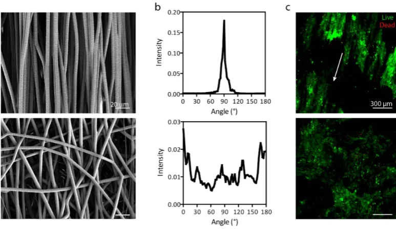
3.3.1 Fabrication of microfibrillar scaffolds with defined architectures ... 61
3.3.2 MSCs adopt distinct morphologies in response to CTGF and TGF-β3 stimulation depending on the alignment of the underlying substrate ... 64
3.3.3 MSCs display distinct gene expression profiles in response to CTGF and TGF-β3 stimulation that depend on the underlying substrate alignment ... 66
3.3.4 Sequential supplementation with CTGF and TGFβ3 supports fibrocartilaginous differentiation on microfibrillar scaffolds ... 69
3.3.5 Growth factor stimulation regulates tissue development with MSC-seeded electrospun scaffolds ... 72
3.3.6 Culturing a scaffold with spatially defined presentation of CTGF and TGFβ3 ... 77
3.4 Discussion ... 78
3.5 Conclusions ... 85
Electrospinning of human scale microfibrillar scaffolds for ligament tissue engineering 87 4.1 Introduction ... 87
4.2 Materials and Methods ... 89
4.2.1 Electrospinning ... 89
4.2.2 Alignment and diameter of microfibers ... 91
4.2.3 Indirect measurements of fibre welding in electrospun-sheets ... 92
4.2.6 Mechanical testing ... 93
4.2.7 Differential scanning calorimetry (DSC) analysis ... 94
4.2.8 Microcomputed tomography (µCT) scans for 3D geometry ... 95
4.2.9 Density of the fibre bundles, porosity and pore size ... 96
4.2.10 Validating cell infiltration potential ... 97
4.2.11 Culture conditions for MSC differentiation ... 97
4.2.12 Gene expression ... 98
4.2.13 Statistical analysis ... 99
4.3 Results ... 100
4.3.1 Fabricating bundles of aligned PCL fibres using high speed electrospinning .. 100
4.3.2 The mechanical properties of electrospun fibre bundles are strongly dependent on the rotational velocity of the collector ... 105
4.3.3 MSCs rapidly migrate into the highly porous bundles generated by high speed electrospinning ... 112
4.3.4 Evaluating the instructive potential of 3D fibre-bundles towards chondrogenesis and ligamentogenesis ... 116
4.4 Discussion ... 117
4.5 Conclusions ... 123
Assessing the bioactivity of ligament and cartilage derived extracellular matrices (ECM) for interface tissue engineering ... 125
5.1 Introduction ... 125
5.2 Materials and Methods ... 127
5.2.1 Electrospinning ... 127
5.2.2 Solubilization of cartilage and ligament ECM ... 127
5.2.5 Changes in surface composition and ECM distribution ... 130
5.2.6 SEM ... 131
5.2.7 Quantification of immobilized solubilized ECM ... 131
5.2.8 Immobilization of solubilized ECM and collagen type I onto the PCL fibres by physical adsorption for cell culture studies (sections 5.3.2 – 5.3.4) ... 132
5.2.9 Immobilization of solubilized ECM and collagen type I onto the PCL fibres by covalent conjugation for cell culture studies (sections 5.3.2 – 5.3.4) ... 132
5.2.10 Isolation and expansion of mesenchymal stem cells (MSCs) ... 132
5.2.11 Seeding of MSCs on scaffolds and culture conditions ... 133
5.2.12 Cell viability, visualization of cell morphology, and counting of pre-adipocytes 135 5.2.13 Gene expression ... 136
5.2.14 Histology ... 137
5.2.15 Statistical analysis ... 137
5.3 Results ... 138
5.3.1 Characterization of the ECM-functionalized scaffolds ... 138
5.3.2 The bioactivity of solubilized ligament and cartilage ECM ... 145
5.3.3 Effect of solubilized ligament and cartilage ECM on MSC differentiation in the presence of CTGF ... 150
5.3.4 Effect of solubilized ligament and cartilage ECM on MSC differentiation in the presence of TGF-β3 ... 154
5.4 Discussion ... 158
5.5 Conclusions ... 161
6.2 Materials and Methods ... 165
6.2.1 Electrospinning ... 165
6.2.2 Isolation and expansion of mesenchymal stem cells (MSCs) ... 165
6.2.3 Solubilization of cartilage and ligament ECM ... 166
6.2.4 SEM ... 166
6.2.5 Cell viability ... 167
6.2.6 Gene expression ... 167
6.2.7 DNA quantification ... 168
6.2.8 Study 1. Finding the appropriate composition of culture media ... 168
6.2.9 Study 2. Coating of electrospun PCL scaffolds with hydroxyapatite ... 170
6.2.10 Study 3. Controlling the spatial presentation of ECM components and growth factors ... 172
6.2.11 Statistical analysis ... 174
6.3 Results ... 175
6.3.1 Finding the appropriate culture media composition ... 175
6.3.2 Hydroxyapatite coating ... 178
6.3.3 Spatial functionalization of scaffolds with ECM and growth factors ... 181
6.4 Discussion ... 185
6.5 Conclusions ... 188
Discussion and conclusions ... 189
7.1 Limitations ... 193
7.2 Conclusions ... 196
7.3 Future work ... 197
Figure 1.1 Gross observation and histology images of the ACL ... 7
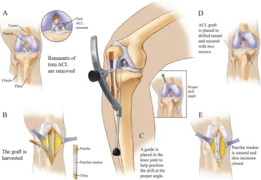
Figure 1.2 Schematics of ACL reconstructionusing a patella tendon-bone graft. ... 8
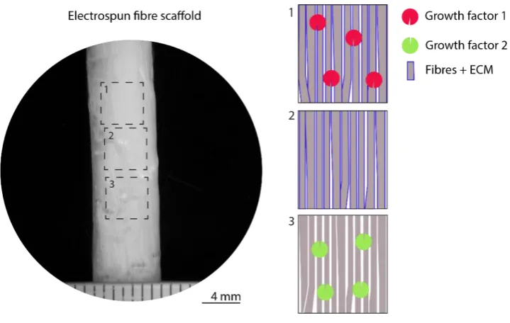
Figure 1.3 Electrospun fibre scaffold spatially functionalized with extracellular matrix (ECM) and/or growth factors within appropriate regions of the construct for (1) mineralized, (2) cartilage, (3) ligament regions ... 12
Figure 2.1 Types of ligament/tendon-bone insertions ... 14
Figure 2.2 Histology sections of tendons. ... 16
Figure 2.3 Mineralized and unmineralized fibrocartilage in the enthesis ... 17
Figure 2.4 Structural hierarchy of ligaments and tendons ... 19
Figure 2.5 The structure of tendon and ligament fibres changes before attaching to bone. .. 21
Figure 2.6 ACL stretch longitudinally. ... 22
Figure 2.7 Mineral distribution at the enthesis. ... 24
Figure 2.8 Contribution of the Scx+/Sox9+cell lineage to the formation of ligaments and the entheseal side of tendons ... 28
Figure 2.9 Establishment of the junction between cartilage and tendon/ligament along the Scx/Sox9 axis.. ... 29
Figure 2.10 A fibrocartilaginous transition zone did not develop between the supraspinatus tendon and the humeral head until postnatal time points (Toluidine blue stain). ... 31
Figure 2.11 Electrospinning process. ... 34
Figure 2.12 Twisted fibres into 3D scaffolds for ACL reconstruction. ... 39
Figure 2.13 Fibre-based scaffolds incorporating bony regions. ... 40
Figure 2.14 Formation of brushite cement anchor/tissue interface.. ... 41
Figure 2.15 Graded scaffolds.. ... 43
GAG incorporating a mineralized matrix. ... 45
Figure 3.1 Microfibrillar scaffolds with specific fibre diameter and alignment ... 62
Figure 3.2 Live-dead staining at day 20. ... 63
Figure 3.3 Fibre alignment and growth factor stimuli influence MSC morphology. ... 64
Figure 3.4 Number of clusters and cluster’s area in TGF-β3-stimulated cells on aligned and randomly-aligned scaffolds at 5% O2 ... 66
Figure 3.5Gene expression at day 10 ... 67
Figure 3.6 qRT-PCR gene expression at day 10 in lower cell-seeding density groups. ... 68
Figure 3.7Gene expression at day 20. ... 71
Figure 3.8Evaluation of DNA, collagen and sGAG content. ... 73
Figure 3.9 Immunohistochemistry of collagen type I.. ... 74
Figure 3.10 Immunohistochemistry of collagen type III. ... 75
Figure 3.11 Immunohistochemistry of collagen type II.. ... 76
Figure 3.12 Aligned scaffolds seeded with MSCs and cultured in both CTGF and TGFβ3 using a dual-chamber ... 78
Figure 3.13 Graphical summary of the findings. ... 83
Figure 4.1 Bundling of fibres sheets collected at low and high speeds. ... 91
Figure 4.2 Characterization of the microfibers and MSC-microfibers interaction ... 102
Figure 4.3 MSC viability and cell morphology. ... 103
Figure 4.4 Load-strain curves of fibre-sheets when loaded perpendicular to the fibre axis. 104 Figure 4.5 Mechanical properties increase as collection velocity increases ... 106
Figure 4.6 Stress-strain curves of 500, 1500, 2500 and 3500 RPMs ... 107
Figure 4.7 Material properties using the cross-sectional area (CSA) of compressed bundles and the theoretical CSA. ... 108
Figure 4.11 Cell morphology and gene expression of MCS on fibre-bundles. ... 117
Figure 5.1 Basal media composition was favorable for MSCs with the addition of CTGF ... 135
Figure 5.2 Characterization of the ECM and of the ECM-functionalized scaffolds. ... 139
Figure 5.3 Hydrolysis of polycaprolactone with NaOH to expose carboxylic groups. ... 141
Figure 5.4 Atomic composition of the PCL scaffolds before and after alkaline hydrolysis.. .. 142
Figure 5.5 ECM components were covalently conjugated onto the hydrolysed PCL surface by a condensation reaction between the carboxylic acid groups on the hydrolysed PCL surface and the primary amines (-NH2) of ECM components using carbodiimide chemistry ... 143
Figure 5.6 XPS spectrum of bare PCL and scaffolds that underwent collagen immobilization. ... 144
Figure 5.7 Live/dead staining (green: ‘live’, red: ‘dead’) of MSCs 24 h after seeding ... 146
Figure 5.8 Cell nuclei (blue) and F-actin (green) staining of MSCs on bare and functionalized scaffolds in the absence of growth factors ... 147
Figure 5.9 Circularity, aspect ratio and area of MSCs in the absence of growth factors. ... 148
Figure 5.10 Gene expression of cartilage and ligament genes of MSCs in the absence of growth factors. ... 149
Figure 5.11 Cell nuclei (blue) and F-actin (green) staining of MSCs on bare and functionalized scaffolds in the presence of CTGF. ... 151
Figure 5.12 Circularity, aspect ratio and area of MSCs stimulated with CTGF. ... 152
Figure 5.13 Gene expression of cartilage and ligament genes in MSCs stimulated with CTGF ... 153
Figure 5.14 Cell nuclei (blue) and F-actin (green) staining of MSCs on bare and functionalized scaffolds in the presence of TGFβ3. ... 155
β3. ... 157
Figure 5.17 Histology images of Picrosirius red and Alcian blue for the TGF-β3 ... 158
Figure 6.1 Schematic representation of the regions in the scaffolds. ... 172
Figure 6.2 Immobilization of growth factors on ECM-PCL scaffolds ... 174
Figure 6.3 Viability of MSCs seeded on to the scaffolds after 10 days in culture. ... 176
Figure 6.4 DNA quantification and gene expression of MSCs at day 10 ... 177
Figure 6.5 The effect of hydroxyapatite (HA) coating on cell viability and gene expression of MSCs after 10 days in culture.. ... 180
Figure 6.6 Viability and morphological differences of MSCs within each one of the regions.. ... 182
List of Tables
Table 2.1 Human ACL mechanical properties ... 26
Table 2.2 Expression of matrix and growth factor genes during tendon-to-bone insertion development, localized to the four insertion zones. ... 30
Table 3.1 Primer sequences used for qPCR... 58
Table 4.1 Primer sequences used for qPCR... 99
Table 4.2 Airflow generated at each RPM ... 103
Table 4.3 Material properties of the bundles calculated using the apparent cross-sectional area. ... 107
Table 4.4 Material properties calculated using the compressed CSA (true material CSA)109 Table 4.5 Material properties calculated using the theoretical CSA ... 109
Table 4.6 Thermal properties of bulk and electrospun PCL fibres ... 110
Table 5.1 Primer sequences used for qPCR... 137
Table 5.2 Chemical composition of PCL scaffolds after physical or chemical immobilization ... 144
Table 6.1 Primer sequences used for qPCR... 168
Table 6.2 Supplements for each media composition for CTGF-mediated fibrogenesis. .. 169
Table 6.3 Supplementsfor each media composition for TGFβ3-mediated chondrogenesis.170 Table 6.4 Reagents for preparing 1X SBF (pH 7.4, 1L) ... 171
Table 6.5 Reagents for preparing 10X SBF (pH 4.3, 1L) ... 171
Nomenclature
3D Three dimensional
ACAN Aggrecan
ACL Anterior cruciate ligament
ALP Alkaline phosphatase
ANOVA Analysis of variance
BMP Bone morphogenetic protein
BSA Bovine serum albumin
CDM Chemically defined medium
C-ECM Decellularized cartilage extracellular matrix COMP Cartilage oligomeric matrix protein
CSA Cross-sectional area
CTGF Connective tissue growth factor DAB 3,3’ Diaminobenzidine
Dil 1,1'-Dioctadecyl-3,3,3',3'-Tetramethylindocarbocyanine Perchlorate
DSC Differential scanning calorimetry
ECM Extracellular matrix
EDC 1-Ethyl-3-(3-dimethylaminopropyl)carbodiimide EDTA Ethylenediaminetetraacetic Acid
FBS Fetal bovine serum
FGF Fibroblastic growth factor
GAG Glycosaminoglycan
GAPDH Glyceraldehyde-3-phosphate dehydrogenase
HA Hydroxyapatite
H&E Haematoxylin and Eosin
L-ECM Decellularized ligament extracellular matrix
MMP Matrix metalloproteinase
MSC Mesenchymal stem cell
NFC Non-mineralized fibrocartilage
NHS N-Hydroxysuccinimide
PBS Phosphate buffered saline
PCL Polycaprolactone
sGAG Sulphated glycosaminoglycan
SEM Scanning electron microscopy
TE Tissue engineering
TGFβ3 Transforming growth factor β3
µCT Micro-computed tomography
XPS X-ray photoelectron spectroscopy
Publications
Journal publications
Olvera, D., Sathy, B. N., Kelly, D. J. 2017. Modulating microfibrillar alignment and growth factor stimulation to regulate mesenchymal stem cell differentiation. Acta Biomaterialia 64, 148-160.
Conference abstracts
Olvera, D., Sathy, B. N., Kelly, D. J. Developing a platform that coaxes adult stem cells to recapitulate the bone-ligament interface. Proceedings of the 22nd Annual Conference of the
Section of Bioengineering of the Royal Academy of Medicine in Ireland, January 2016, Galway,
Olvera, D., Sathy, B. N., Kelly, D. J. 2017. Integrating biochemical and topographical cues to direct stem cell fate. Tissue Engineering and Regenerative Medicine International Society (TERMIS), European Chapter, June 2016, Uppsala, Sweden.
Olvera, D., Sathy, B. N., Kelly, D. J. 2017. Microfibrillar scaffolds incorporating spatially defined extracellular matrix components for bone-ligament junction regeneration. Proceedings of the
23rd Annual Conference of the Section of Bioengineering of the Royal Academy of Medicine in
Ireland, January 2017, Belfast, United Kingdom.
Olvera, D., Sathy, B. N., Kelly, D. J. 2017. Modulating microfibrillar topography, collagen presentation and growth factor stimulation to regulate MSC differentiation for interface tissue engineering. Orthopaedic Research Society (ORS), March 2017, San Diego, United States of America.
Introduction
1.1 Anterior cruciate ligament and repair
While certain ligaments can be repaired by suturing the injured tissue back together, repairing ligaments that do not heal (commonly the ACL and PCL) requires the use of autografts or allografts (Woo et al., 2006). In current ACL reconstructions, the torn ligament is resected along with the fibrocartilaginous interface and bone from the drilled tunnel and the entire ligament unit is replaced by a homogenous autologous or allogeneic tendon graft (Figure 1.2). Both replacements have inherent limitations. The harvest of autologous tendon grafts such as the middle third of the patellar, hamstring or quadriceps tendon is the preferred option for ACL reconstruction; however, it results in a second surgical site with potential complications such as rupture of donor tendon, chronic pain, and decreased muscle strength at the donor site (Aune et al., 2001; Kartus, Movin and Karlsson, 2001; Spindler et al., 2004). The use of an allogeneic tendon from deceased donors avoids damaging healthy tissue, but risks pathogen transmission and are in limited supply (Pedowitz, O’Connor and Akeson, 2003). Synthetic grafts have been developed to address these limitations, but so far have displayed limited success (Legnani et al., 2010). Synthetic ACL grafts include the Ligament Augmentation and Reconstruction System (LARSTM, polyethylene terephthalate) (Smith et al., 2014), Leeds-Keio ligaments such as Poly-Tapes (polyethylene terephthalate) (Murray and Macnicol, 2004),
Figure 1.2 Schematics of ACL reconstruction using a patella tendon-bone graft. A, Remnants of the torn ACL are cleared. B, The graft is harvested; typically an autologous or allogenic tendon graft; in this case a patella tendon with bone plugs at distal ends. C, A guide is placed in the knee joint to help position the drill at the proper angle. D, The ACL graft is placed in the drilled tunnel and secured with two screws. E, The patellar tendon is sutured and the skin incisions closed (Image from compelvisuals.com).
number of revision surgeries has increased significantly (Lu and Jiang, 2006), providing evidence that inadequate tissue integration, poor graft remodelling and a failure to re-establish a normal enthesis severely limits the initial mechanical properties of the ligament substitutes used in the clinical setting (Rodeo et al., 1999). Revision rates are as high as 28% in adolescents (Deneweth et al., 2010; Ellis et al., 2012; Engelman et al., 2014; Faunø, Rahr-Wagner and Lind, 2014b).
The long-term functional outcome of the ACL after reconstruction largely depends on the integration of the graft with the host bone and the re-establishment of the enthesis. However, the torn ligament is replaced by a tendon graft that fails to regenerate the enthesis. The interface formed is a loose fibrovascular scar tissue with inferior mechanical properties (Rodeo et al., 1993; Chen, 2009; D. Lee et al., 2014). This predisposes the tissue at the bone insertion site to high stress concentrations which is believed to contribute to the high re-failure rates.
1.2 Interface tissue engineering
TE approaches aim to overcome the shortcomings associated with existing ACL reconstruction techniques. It is believed that by developing a bioactive construct capable of osteointegration with the host subchondral bone, and by regenerating the transition zones of the enthesis, it is possible to develop a functional ACL repair (Phillips et al., 2008; Caliari et al., 2015). While several studies have successfully reproduced the ligament and the bone regions of such a unit, recapitulation of the fibrocartilaginous interface region remains a challenge. Notable examples have developed stratified scaffolds using multiple cell types (namely fibroblasts, chondrocytes, and osteoblasts) to recapitulate the heterogeneity of cells at the interface (Spalazzi et al., 2008; Li et al., 2016). These scaffolds supported multilineage cellular interactions and tissue infiltration, and induced zone-specific matrix production in vivo (Spalazzi et al., 2008). Other studies have designed biomaterials to mimic the architecture and/or composition of different regions of the bone-ligament interface to provide biophysical and biochemical cues to resident cells (Spalazzi et al., 2006; Phillips et al., 2008; Xie et al., 2010; Samavedi et al., 2012; Caliari et al., 2015; Criscenti et al., 2016; Li et al., 2016). These studies stress the need for distinct zones to guide and maintain distinct cellular regions and phase-specific extracellular matrix deposition. Examples of such strategies include the design of scaffolds with spatial variation in biochemical cues such as the incorporation of calcium-phosphate, while achieving associated mechanical gradients (Phillips et al., 2008; Li et al., 2009; Xie et al., 2012). The calcified region in the scaffold is thought to enhance osteointegration with the host bone and a graded overlapping matrix between the main body of the ligament and the calcified tissue is thought to mimic aspects of the enthesis.
1.3 Objectives
The objective of this thesis is to develop a mechanically functional, spatially defined scaffold for ligament tissue engineering with the potential to regenerate the stratified interface between ligament and bone. It is hypothesized that an electrospun fibre scaffold spatially functionalized with extracellular matrix (ECM) and/or growth factors can direct the differentiation of mesenchymal stem cells (MSCs) down the ligament, cartilage, and endochondral/bone pathways within appropriate regions of the construct (see Figure 1.3). This hypothesis has been motivated by observations reported in literature of how these factors in isolation regulate stem cell differentiation (Cardwell, Dahlgren and Goldstein, 2014; Yin et al., 2015; Rothrauff, Yang and Tuan, 2017). This hypothesis will be tested using electrospun polycaprolactone (PCL) microfibers as a scaffolding biomaterial. The first part of
Figure 1.3 Electrospun fibre scaffold spatially functionalized with extracellular matrix (ECM) and/or growth factors within appropriate regions of the construct for (1) mineralized, (2) cartilage, (3) ligament
[image:32.595.106.466.68.296.2]Literature Review
2.1 Structure and function of the bone-ligament
interface
The basic function of any enthesis it to attach the ligament or tendon to the skeleton; this function is central to force transmission. Two different types of enthesis can be distinguished: fibrous and fibrocartilaginous (Benjamin and Ralphs, 1998). In a fibrous enthesis, Sharpey’s collagen fibres connect the ligament and bone forming acute angles, for example in the interface between the periodontal ligament and the alveolar bone (Figure 2.1 a). These collagen fibres are inserted into bone via the periosteum, which gives a firmer hold to short ligaments and tendons. The fibrocartilaginous entheses found in ligaments such as the anterior cruciate ligament (ACL), which connects the femur and tibia, are more common
a b
c
[image:34.595.70.495.74.581.2]The ACL originates at the femoral condyle and runs distal to the insertion at the tibial eminence. Due to its orientation within the knee joint, it restrains the anterior tibial translation and the internal rotation of the knee (Dienst, Burks and Greis, 2002). The ACL-to-bone interface is relatively small, in the order of 100 μm – 1mm, depending of the species and age (Wang et al., 2006). The ACL-to-bone is avascular at insertion sites and within fibrocartilage zone, only the ligament portion is vascularized from the middle genicular artery and vessels of the infrapatellar fat pad and adjacent synovium (Toy et al., 1995). Both, the femoral and the tibial junctions are composed of four distinct tissues along the entheses: (1) ligament, composed of a relatively small fraction of parenchymal fibroblasts (with a cell density 810 ± 81 /mm2) characterized by low mitotic activity (Doroski, Brink and Temenoff, 2007) and low
a mechanical role in bundle reorganization following ligament deformation (Smith et al., 2011). Adjacent to the ligament is the (2) fibrocartilage.
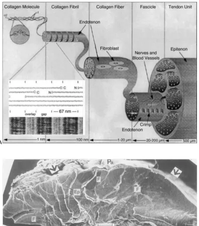
Figure 2.2 Histology sections of tendons. a, Longitudinal section of a portion of a typical tendon showing elongated fibroblasts arranged in longitudinal rows (arrow) between parallel arrays of collagen fibers. All that is visible of the cells are the elongated and darkly stained nuclei. b, Transverse section of a multifascicular tendon. The arrows highlignt the thin films of loose connective tissue endotenon around a fascicle (F). Within each fascicle and in the endotenon, the dark dots are the nuceli of fibroblasts. Sections are stained with H&E. c, Confocal laser scanning microscopy images of rat digital flexor tendons
cut in transverse section. 3D projection of a fascicle stained with Dil to highlight the cells. The fascicle is bounded by endotenon (arrows), and the collagen fibers within it are unstained but would fill the dark areas (Benjamin and Ralphs, 2000).
at which material has accumulated (Benjamin, Evans and Copp, 1986). In the case of the ACL, which enthesis is immediately adjacent to articular cartilage, then the tidemark is continuous across both (Benjamin, Evans and Copp, 1986). The mineralized fibrocartilage interfaces
directly with the (3) subchondral bone, composed predominantly of hydroxyapatite and type
[image:37.595.119.513.297.630.2]I collagen populated by osteoblasts, osteocytes and osteoclasts (Moffat et al., 2008). Apart from their mineralization potential, ACL enthesis fibrochondrocytes behave more similar to articular chondrocytes than to meniscal fibrochondrocytes or ligament fibroblasts in terms of growth rate and biosynthesis (Sun, Moffat and Lu, 2007).
Figure 2.3 Mineralized and unmineralized fibrocartilage in the enthesis. Raman microprobe analysis of developing supraspinatus tendon (SS) insertion. Top row (A-C) shows a P7 insertion, middle row (D-F) a P14 insertion, and bottom row (G-I) a P28 insertion. The insertion is populated by fibrochondrocytes (note the pericellular region). Left column, A, D, G: 20 μm-thick sections stained with toluidine blue and according to von Kossa’s method (scale bar= 50 μm). Note that despite the sharp front of mineralization in these figures suggested by the von Kossa staining, a graded mineralization front is evident from the Raman scans. Middle column B, E, H: magnified view of square region of interest shown in images in
heights of 960 Δcm-1 to 1003 Δcm-1 Raman peaks (corresponding to the v1 P-O stretching band of
hydroxyapatite and the aromatic ring stretching band of phenylalanine in collagen, respectively) is indicated by the colour gradient of the overlaid points. SS: supraspinatus tendon and H: humeral head. Right column C, F, I: baseline-corrected Raman spectra corresponding to points along a traverse from tendon (no mineral - dark blue) to bone (high mineral - red). The mineral peak (960 Δcm-1) is indicated
with a hollow arrow and the collagen peak (1003 Δcm-1) is indicated with a black-filled arrow (Schwartz et al., 2012).
Even though the entheses of the ACL are composed of the same structure compartments, there are differences in anatomy between the femoral and tibial entheses. The femoral enthesis exhibits a more acute ligament attachment angle than the tibial enthesis and greater calcified and uncalcified fibrocartilage area and depth. This might explain why the femoral origin is more vulnerable to failure (Beaulieu et al., 2015).
The bone-ligament construct behaves as a multiphasic fibre-reinforced, nonlinear viscoelastic, anisotropic material that exhibits high tensile strength and stiffness, allowing it to withstand millions of cycles of load over a lifetime. These complex mechanical properties arise from its heterogeneous extracellular matrix (ECM) content, decreasing fibre orientation and increasing mineral concentration, explaining site-specific stiffness over the length of the construct.
A
[image:39.595.116.518.70.526.2]B
Figure 2.4 Structural hierarchy of ligaments and tendons. A, Collagen molecules form a collagen fibril. Each collagen fibril is covered by a thin layer of endotenon. Fibrils are grouped to form collagen fibres which are populated by fibroblasts. A group of collagen fibres organize to form fascicles. A ligament or tendon unit is composed of many fascicles (Silver, Freeman and Seehra, 2003). B, SEM micrograph of tibial cross-section of a canine ACL showing individual fascicles delineated by epitenon (Ep) on the left and a single fascicle (F) on the right. The sheath seen on the anterior side of the ligament (arrow) is the paratenon (Pa) embedded in a loose connective tissue (Yahia and Drouin, 1989).
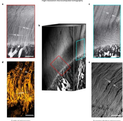
bundles (Silver, Freeman and Seehra, 2003). As the ligament or tendon enters the interface, the collagen fibres unravel into thinner interface fibres before attaching to bone (Rossetti et al., 2017). (Figure 2.5). Glycoproteins and glycosaminoglycans enable the ligament to
distribute stresses uniformly. Proteoglycans add lubrication and viscoelasticity to the matrix acting as a hydraulic damper, as well as allowing the fascicles to slide past each other
Figure 2.5 The structure of tendon and ligament fibres changes before attaching to bone. Enthesis high-resolution microcomputed tomography (μCT) and confocal reflection imaging as well as scanning electron microscopy show that fibres continue from tendon towards bone. Fibres unravel into thinner interface fibres upon entering the interface region with spans ~500 μm between bone and tendon. a,
Interface fibres observed with high-resolution μCT. b, Rendered volume of μCT acquisition showing both interface fibres as well as tendon fibres. c, Tendon fibres in μCT. d, Tendon fibres and interface fibres imaged with confocal reflection microscopy of enthesis cryocut sections. e, Tendon fibres observed with scanning electron microscopy. White arrows mark fibre width. Scale bars, 250 μm (Rossetti et al., 2017).
Ligaments contain a large amount of highly organized collagen to withstand the large tensile stresses it is subjected to, while tissues subjected to compressive loading (e.g. articular cartilage and the nucleus pulposus of the intervertebral disc) contain large amounts of
compression and therefore fibrochondrocytes secrete an ECM rich in aggrecan and densely packed collagen type II fibres (Nerurkar et al., 2011). The compressibility of fibrocartilage enables it to dissipate stress at the ligament-bone junction and to absorb shock. Without the fibrocartilagenous zone, the mechanical mismatch at the interface between two different tissues would result in stress concentrations (Benjamin and Ralphs, 1998). From testing bone-ligament-bone constructs in tension, it is known that the construct deforms non-uniformly upon stretch, with the highest deformation occurring near or at the ligament insertion sites to bone (Woo et al., 1983). As the ACL stretches, the fibrochondrocytes in the non-mineralized fibrocartilage zone act like taut springs resisting transverse shortening in response to the stretch (Figure 2.6). The ligament is loaded primarily in tension, the fibrocartilage enthesis is subjected to tensile, shear and compressive components.
Figure 2.6 ACL stretch longitudinally. As the ACL stretches longitudinally, the fibrochondrocytes in the non-mineralized fibrocartilage zone act like taut springs resisting transverse shortening in response to the stretch (Schünke et al., 2006). Finite-element analysis of a medial collateral ligament (MLC) loaded in tension predicts that the largest principal tensile stresses happen at the ligament midsubstance, and the greatest principal compressive stresses occur near the distal edge of the MCL-to-bone insertion (Matyas et al., 1995).
Calcium and phosphate mineral content increases from ligament to bone (Figures 2.3
Property Reported values for human ACL Observations
Length ~32 mm (Amis and Dawkins,
1991)
Crimp structure allows for 7-16% of creep prior permanent deformation and ligament damage (Vunjak-Novakovic et al., 2004).
Width 7 – 12 mm (Amis and Dawkins,
1991)
Cross-sectional area 44 – 58 mm2 (Noyes and Grood,
1976; Bonnin et al., 2012)
Femoral attachment area in the human ACL is
113 mm2 and 136 mm2
at the tibia insertion (Harner et al., 1995). Tensile forces 67 N (for ascending stairs) – 630
N (jogging) (Chen and Black, 1980)
Maximum stress 13.3 MPa (> 48 yrs.) – 38 MPa (
16-26 yrs) (Noyes and Grood,
1976) Strain at maximum
stress
30 % (> 48 yrs.) – 45% ( 16-26 yrs) (Noyes and Grood, 1976)
Ultimate load Tensile strength
1725 ± 269 N (Canale and Beaty, 2012); in younger specimens (22-35 yrs.) 2160 ± 157 N (Woo et al., 1991)
1,730 N is the
established standard for ACL grafts (Vunjak-Novakovic et al., 2004)
Stiffness/ Linear stiffness
182 ± 33 N/mm (Canale and
Beaty, 2012); in younger specimens (22-35 yrs.) 242 ± 28
N/mm(Woo et al., 1991)
182 N/mm is the established standard for ACL grafts as reported by (Vunjak-Novakovic et al., 2004)
Yield point ~1200 N (Noyes and Grood, 1976)
Energy absorbed to failure
12.8 ± 2.2 N-m (Canale and Beaty, 2012)
12.8 N-m is the
established standard for ACL grafts (Vunjak-Novakovic et al., 2004)
Glycosaminoglycan (GAG) content
7.4 μg/mg (Amiel et al., 1983)
Total collagen (%) (mg of collagen/ g of dry tissue) for cruciate ligaments
80.3 ± 1 (Amiel et al., 1983) ACL and PCL combined
Elastic modulus The Young’s modulus of ACL is 111 ± 26 MPa for younger humans (16–26 years) and 65 ± 24 MPa for older humans (48– 86 years) (Noyes and Grood,
1976)
Table 2.1 Human ACL mechanical properties
2.2 Developmental process of the ligament to bone
insertion
Progenitors for tendons, ligaments, cartilage and bone originate from the sclerotome, the lateral plate mesoderm and the neural crest (Mori-Akiyama et al., 2003; Christ, Huang and
Scaal, 2004; Akiyama et al., 2005). These progenitor populations migrate and settle in the prospective area to give rise to tendon, ligament, and cartilage primordia during early stages of musculoskeletal development (Sugimoto, Takimoto, Akiyama, et al., 2013). Each primordium for the musculoskeletal component initially develops as an individual unit, but later they integrate with each other. To achieve the tendon/ligament-bone integration, progenitors of tendon/ligament and bone establish a coordinated development that involves SYR-box containing gene 9 (Sox9) and scleraxis (Scx) (Sugimoto, Takimoto, Akiyama, et al.,
to fibrochondrocytes. The cellular origin of fibrochondrocytes remains uncertain, but it is known that entheseal fibrocartilage develops in response to compressive loads postnatally (Benjamin and Ralphs, 1998).
Figure 2.8 Contribution of the Scx+/Sox9+ cell lineage to the formation of ligaments and the entheseal
side of tendons. a, Distribution of Sox9+ and Sox9- cells in Scx+ region of mouse embryos. In ScxGFP
transgenic mouse embryos, Sox9+ cells (red) and Scx+cells expressing GFP (green) were detected by
double immunostaining with antibodies specific for Sox9 and GFP, respectively, and nuclei were stained
with DAPI (blue). Scx+/Sox9+ chondrogenic cells are found in the entheseal region of the Achilles tendon
(At) and the calcaneus (ca) at E14.5 (merged image). Scale bar, 100 μm. b, Contribution of Sox9+
progenitors to axial tendon and ligament formation. Sections were prepared from Sox9Cre/+;Ai14;ScxGFP
embryos and cells of the Sox9+ lineage were detected by tdTomato reporter expression and Scx+ cells
were detected with anti-GFP antibody. Shown is a sagittal section of the developing tail, with arrows and arrowheads indicating tendons associated and not associated with the vertebrae, respectively. Rostral and caudal sides are indicated by r and c, respectively. Scale bar, 200 μm. c, Distribution of
Scx-expressing tendons and ligaments (GFP, green) with a Sox9 expression history (tdTomato, red) were analysed in a Sox9Cre/+;Ai14;ScxGFP mouse embryo at E14.5. Image shows sagittal section of the
hindlimb. Arrows and arrowheads indicate tendon and ligaments, respectively. White and yellow arrows in (c) indicate the force-transmitting and the anchoring tendons at the lower leg, respectively. The boxed region in (c) is shown at a higher magnification in (d). This analysis shows that the insertion sites of the tendons into the vertebrae were derived from Scx+/Sox9+ progenitors, whereas tendons located
further away from vertebrae were almost exclusively Sox9- and Scx+ (Sugimoto, Takimoto, Akiyama, et
Figure 2.9 Establishment of the junction between cartilage and tendon/ligament along the Scx/Sox9
axis. A, Differentiation of the tendogenic, ligamentogenic and chondrogenic cell lineages along the
Scx/Sox9 axis. The differentiation pathways of Scx-/Sox9+ chondroprogenitors (CP), Scx+/Sox9+
teno-/ligamento-/chondroprogenitors (TLCP) and Scx+/Sox9- tenoprogenitors (TP) are shown. B,
Establishment of the chondro-tendinous/ligamentous junction (CTJ/CLJ) to form the osteo-tendinous/ligamentous junction (OTJ/OLJ). Scx+/Sox9+ progenitors give rise to the primordial CTJ/CLJ.
The established CTJ/CLJ further develops to form the OTJ/OLJ during postnatal growth. Expression levels of Sox9 and Scx are represented in dark and light grey, respectively (Sugimoto, Takimoto, Akiyama, et
al., 2013).
muscle loading was not required for initiation of enthesis formation, but it was necessary for subsequent growth and maturation of the enthesis (Blitz et al., 2009)
Time point Zone 1: tendon/
ligament
Zone 2:
fibrocartilage mineralized Zone 3: fibrocartilage
Zone 4: bone
13.5 dpc Col I, TGFβ3 - - Col II
15.5 dpc Col I, TGFβ1, 3 - - Col II
18.5 dpc Col I, TGFβ1 - - Col II
Neonatal Col I - - Col II
3 days Col I - - Col II
7 days Col I Col I, II Col II Col II
14 days Col I Col I, II Col II, X Col II
21 days Col I Col I, II Col II, X Bone
28 days Col I Col I Col II, X Bone
56 days Col I Col I Col II, X Bone
Table 2.2 Expression of matrix and growth factor genes during tendon-to-bone insertion development, localized to the four insertion zones. dpc, days postconception; -, zones not yet distinct (Galatz et al.,
2007). The fibrocartilaginous zone of the tendon insertion site develops at approximately 14 days postnatally in murine model.
At 13.5 dpc, chondrocytes expressing type II collagen formed the humeral head. At
morphology and expressed type II collagen. At 14 days, the hypertrophic chondrocytes near the tendon insertion started to express collagen type X. At this time-point, chondrocytes were absent in the bone next to the insertion. At 21 and 28 days, a four-zone transition was apparent between the supraspinatus tendon and the humeral head. Fibroblasts in the tendon (zone 1) expressed type I collagen, fibrochondrocytes in zone 2 expressed collagen types I and
II, hypertrophic chondrocytes in zone 3 expressed collagen types II and X, and mature bone
was evident in zone 4. At 56 days, the expression patterns for collagen I, II, and X were identical to the previous time-points, the four-zone insertion site was clear between tendon and bone. Notably, hypertrophic chondrocytes were no longer present at the mature insertion, while expression of type X collagen persisted. Similar patterns have been described for rat Achilles tendon insertions and for bovine ACL insertions postnatally (Fujioka et al., 1997; Wang et al., 2006).
Figure 2.10 A fibrocartilaginous transition zone did not develop between the supraspinatus tendon and the humeral head until postnatal time points (Toluidine blue stain). A, 15.5 dpc; B, neonatal; C, 21 days. s, supraspinatus tendon; h, humeral head; i, interface(Galatz et al., 2007).
The way the hypertrophic chondrocytes express type X collagen to form the mineralization front of the insertion (zone 3) is in a similar pattern to that seen at growth
cartilaginous regions (such as in growth plates and fracture callous), it persists in areas with strict delineation between bone and soft tissue (e.g. tendon/ligament insertion sites). Collagen X may have a key role in maintaining the distinct zones between mineralized and unmineralized soft tissues. It has been demonstrated that instead of co-developing with fibrocartilage, the mineral gradient is constitutive to mineralization fronts associated with endochondral ossification (Schwartz et al., 2012). Mineralization front is evident adjacent to the developing soft tissue by 14 days postnatally.
The factors that modulate growth plate maturation also play a role in enthesis formation. Specifically, the Indian hedgehog (Ihh)/parathyroid hormone–related protein (PTHrP) feedback loop is critical for mineralization at the growth plate (Lu and Thomopoulos,
2013). The Ihh/PTHrP loop regulates chondrocyte differentiation and homeostasis and thus could play a role in enthesis development. PTHrP, for example, prevents proliferating chondrocytes in the growth plate (or other proliferative zones) from becoming hypertrophic chondrocytes (which eventually mineralize). PTHrP maintains a population of proliferative
chondrocytes available for growth rather than for hypertrophy and mineralization. Graded
expression of Ihh and PTHrP at the enthesis may regulate the formation of a graded transition between mineralized and unmineralized tissue (Lu and Thomopoulos, 2013).
2.3 Electrospinning
high voltage electric field is applied to a viscous polymer solution, a continuous jet of polymer from the nozzle is deposited onto an oppositely charged grounded collector. The potential difference between the needle tip and the collector draws the polymer as a jet towards the oppositely charged collector. In the absence of the electric field the polymer droplet is held at the capillary tip by surface tension of the liquid; when the electric field is applied, the droplet elongates and forms a ‘Taylor cone’. When the strength of the electrical field is sufficient to overcome the surface tension of the liquid, the fine fibre jet is ejected from the tip of the Taylor cone. As the fibres jet travels through the air, the solvent evaporates and charged, solid polymer fibres are deposited on the collector where the charges on the fibres are neutralized (Figure 2.11). These fibres are collected in large quantities to produce 3D fibrous scaffolds.
Electrospinning generates fibre scaffolds with high porosities, large surface area-to-volume ratios, and a wide range of fibre diameters by modulating a combination of solution and processing variables in addition to ambient parameters (such as temperature, humidity and air velocity) (Pham, Sharma and Mikos, 2006a). Solution properties include polymer concentration, viscosity, dipole moment, dielectric constant and molecular weight, solvent volatility and conductivity, and surface tension. Processing variables include flow rate, needle size, distance to the collector and applied voltage. An extensive array of polymers can be electrospun, both natural and synthetic, spanning a range of stiffness and fibre diameters (50
Figure 2.11 Electrospinning process. a, The electric field deforms the fluid contained within the needle and forces the formation of a strand. b, A continuous jet of polymer from the nozzle is draw to the grounded collector. c, As the fibre jet travels through the air, the solvent evaporates and solid polymer fibres are deposited onto collector where they are neutralized. d, the collector could be a rotating mandrel (top) or a static plate (bottom).
parameters, there are no defined rules as every polymer-solvent relationship is different, however some of the trends observed in this work using polycaprolactone and chloroform are that fibre diameter increases with increasing polymer concentration. Chloroform shows convenient volatility (similar to tetrahydrofuran (THF), much higher than dimethylformamide (DMF)) which can result in smooth or textured fibres.
The electric field during electrospining elongates and stretches the fibres. The fluid instability in the polymer jet causes whip-like motion in the jet, thereby increasing the degree of stretching before reaching the grounded collector. The elongation that the material experiences can be quantified using the draw ratio. It is calculated as the ratio of collector velocity to ejection velocity of the polymer solution from the tip of the nozzle (Wong, Baji and Leng, 2008). The fibres collected experience a huge material elongation rate and related reduction in the cross-sectional area (order of 10) (Wong, Baji and Leng, 2008). The evaporation of the solvent leads to a gradual increase of the relaxation times, thus the elongation and stretching of the jet that forces the polymer chain to align can be locked by the rapid solvent evaporation. It is a competition between the elongation forces (that orient polymer chains along the deformation direction), and the orientation relaxation of the PCL chains (that promote a return to the equilibrium state). We encouraged the residual solvent to evaporate to lock in the oriented fibre structure (out-of-equilibrium) and to discourage further orientation relaxation after electrospinning.
2.4 Electrospinning for tissue engineering
Besides controlling the fibre diameter, electrospinning allows for fibre alignment. Anisotropy influences directional stiffness as well as to contact guidance where cell phenotype is altered and consequently the structure of the extracellular matrix synthesized. By contact guidance cells respond to structural cues of the substrate to adopt a specific phenotype associated to differentiation into a specific cell lineage. For example. ligamentous differentiation is enhanced in anisotropic scaffolds (Subramony et al., 2013; Yin et al., 2015).
Guiding MSCs towards a specific lineage and maintaining this phenotype involves the
appropriate application of mechanical, chemical and structural cues, acting individually or combined. Several studies have demonstrated that the physical properties of the substrate, such as fibre diameter, length, substrate geometry, scale, cross-linking pattern, topography, stiffness etc. affect the cellular adhesion, degree of cytoskeletal tension, morphology, proliferation, migration and differentiation of MSCs (McBeath et al., 2004; Engler et al., 2006; Dalby et al., 2007; Gentlemanet al., 2009; Lutolf, Gilbert and Blau, 2009; Oh et al., 2009; Chowdhury et al., 2010; Kilian et al., 2010). Furthermore, unlike chemical stimulation, for which time and concentration dependence is difficult to control, topographical cues can be developed with greater control (Subramony et al., 2013). Topographical cues from the extracellular microenvironment can influence cellular proliferation and differentiation. Electrospun fibres, for example, provide contact guidance for cell orientation and migration.
Electrospun fibres have been braided, woven, rolled, fan-folded and knitted to form scaffolds. These scaffolds showed high mechanical strengths compared to hydrogels or self-assembly of cells, and topographical cues to align cells and direct matrix deposition. But dense
3D arrangement hindered cell invasion and minimize diffusion. Nanofiber sheets of tightly
Researchers circumvent these limitations by improving the porosity of the scaffold. Strategies include laser cutting holes in the electrospun sheets (Petrigliano et al., 2015), using a slow rotating frame collector to extend the pore size (Zhu et al., 2008), or layered hydrospinning showing a porosity of 99% (Tzezana, Zussman and Levenberg, 2008). An improvement in cellular infiltration while maintaining alignment has been observed. Another way to circumvent limited porosity in densely packed fibrous scaffolds is co-electropinning sacrificial fibres, typically of water-soluble poly(ethylene oxide) (PEO) (Baker et al., 2008; Ifkovits et al., 2010). Composites of two distinct fibre fractions are electrospun: a
slow-degrading poly(ε-captrolactone) and sacrificial PEO which can be selectively removed to increase pore size. However, the structural integrity of the scaffold was compromised when PEO was greater than 60% (Baker et al., 2008). Electrospinning of salt particles into scaffolds, which are subsequently leached from the system is based on the same principle (Nam et al., 2007).
Although there is a general agreement that aligned fibres are more suitable for ligament differentiation, less of a consensus is reached about fibre diameter. A study aimed to determine the effect of fibre diameter and the degree of fibre alignment on MSCs morphology, proliferation and ligament gene expression, showed that fibroblasts adopted a more spindle-shape morphology on fibres with a diameter of 0.82 – 2.3 μm, but observed a
decrease in the expression of col I, tenomodulin (TNMD) and decorin (DCN) (marker genes of mature ligamentocytes) on these fibres. They concluded that submicron fibres may be preferable for ligament tissue engineering. A recent study from the same group conducted
with the same purpose, reported that fibres larger than 2 μm (opposed to <1μm – <2 μm)
induced highest expression of col I, DCN and scleraxis (Scx); and presumably larger fibres allow larger interfibre spaces for a better diffusion of nutrients and cellular penetration into the electrospun meshes. This is relevant since collagen fibres found in ligament are within the range of 1 – 20 μm (Cardwell, Dahlgren and Goldstein, 2014).
2.5 Strategies to engineer the bone-ligament interface
Tissue engineering strategies have been intensively developed as alternatives to the current standard for ACL reconstruction (e.g. ligament proper) (Altman et al., 2002; Cooper et al., 2005). Early studies in ACL tissue engineering (TE) focused on creating a ligament substitute, overlooking the need for graft integration into bone and for the enthesisdevelopment. Generally, the objective of these early studies was to match the mechanical
requirements of native ACL. For this purpose, silk fibroin fibres twisted or braided into 3D
inhibited by the limited porosity in these twisted/braided scaffolds (Cooper et al., 2007; Freeman, Woods and Laurencin, 2007; Fan et al., 2009). With a similar design, another study braided polylactide-co-glycolide (PLAGA) fibres. The authors emphasized the importance of
porosity for tissue ingrowth (Cooper et al., 2005).
Figure 2.12 Twisted fibres into 3D scaffolds for ACL reconstruction. a, Photograph of a single silk fibroin cord containing a total of 540 individual fibres. Six parallel cords are used to generate the ACL matrix. (bottom) Schematic of an ACL 6-cord matrix hierarchy (Altman et al., 2002). b, Photograph and schematic of silk ACL scaffold with wired architecture.
suggested to combine knitted silk fibroin and collagen to reconstruct a rabbit ACL. Their aim was to assess its in vivo performance compared to an autograft. They observed that compared to the autograft group, the tissue engineered construct osteo-integrated better as there was evidence of trabecular bone growth into the scaffold (Bi et al., 2015) (Figure 2.13).
a b
Figure 2.13 Fibre-based scaffolds incorporating bony regions. a, bony attachments with smaller pore size and lower porosity compared to the middle section (Cooper et al., 2005). b, A rolled-up shaft of silk-collagen scaffold with the two ends clamped by forceps (A). (B) Gross observation of ACL
reconstruction (the black arrow points to the silk-collagen graft). (C) The auto-semitendinosus tendon
(arrow) was harvested before exposing the knee joint. (D) Gross observation of ACL reconstruction (the black arrow points to the autograft) (Bi et al., 2015).
An alternative approach was proposed, by embedding a poly(l-lactide) (PLL) braid into porous poly(1,8-octanediol-co-citric acid)-hydroxyapatite nanocomposite (POC-HA) to create a tri-component graft (i.e. bone-ligament-bone). These grafts were used to reconstruct the ACL of rabbits allowing weight-bearing capability after 6 weeks of implantation. They showed tissue infiltration throughout the entire scaffold, tissue ingrowth and interlocking within the bone tunnels. The authors highlighted the importance of fixation; they attribute some inflammatory response to debris of the POC-HA from micromotions at the bone tunnels (Chung et al., 2014). A potential way to form the 3D arrangement without braiding is to allow the cells to self-organize into a 3D construct. The first report on primary skeletal muscle cells
starfish-shaped muscle structure held in tension by cellular adhesion to stainless-steel pins which eventually developed into connective tissue layers. These newly formed tissue expressed more developmentally mature myosin heavy chains than cells in monolayer culture (Huang et al., 2005). Since then, various groups have largely based their work on this technique for scaffold-free 3D skeletal tissue, especially for muscle tissue (Huang et al., 2005) and then for tendon (Calve et al., 2004) and ligament tissues (Hairfield-stein et al., 2007; Paxton et al., 2010). For example, fibroblasts and brushite (CaHPO42H2O) cement anchors (Paxton et al.,
2010) (Figure 2.14). In most of the scaffold-free approaches, ligament-like tissue forms from the self-assembly of fibroblasts or bone marrow stem cells, however they show poor mechanical integrity orders of magnitude lower than those of native ligament, and there is limited control on the size of the formed sinew.
Figure 2.14 Formation of brushite cement anchor/tissue interface. TE-ligament formation with cell-seeded fibrin gel and brushite cement anchors at 7 days (Paxton et al., 2010).
Various growth factors and gene transfer have been used to augment healing/integration after ACL reconstruction.
The next challenge is engineering the enthesis. Some strategies aim to replicate the complex composite unit of bone–calcified fibrocartilage–fibrocartilage–ligament, as it is an attractive approach serving a twofold purpose: the calcified region in the scaffold is thought to enhance osteointegration with the host bone (Phillips et al., 2008; Caliari et al., 2015); and a graded overlapping matrix between the main body of the ligament and the calcified tissue is thought to mimic the enthesis role in knee homeostasis (Li et al., 2016). To achieve the complexity of this strategy, researchers had focus on multiple cell types, bioinspired stratified or gradient scaffold designs aiming to replicate the structural and compositional heterogeneity inherent across the distinct tissues that make up the enthesis (Spalazzi et al., 2006; Phillips et al., 2008; Samavedi et al., 2012; Caliari et al., 2015; Criscenti et al., 2016; Li et al., 2016). The inherent complexity of achieving these strategies places limitations in the
current studies. Graded scaffolds incorporating an array of different cell types (fibroblasts,
chondrocytes and osteoblasts for the ligament, fibrocartilage and bone phases respectively) have been developed (Spalazzi et al., 2006, 2008; Li et al., 2016) (Figure 2.15). While this approach created zones as seen in the native structure, there are several challenges, including the necessity for multiple cell types. Many studies have attempt to recreate the biochemical composition along the length of the scaffold. Some have demonstrated a gradient of mineral content(Lu and Jiang, 2006; Li et al., 2009), for example, a study combined
polylactidecoglycolide (PLAGA) alone for the ligament region and PLAGA with bioactive glass
(BG) to engineer a composite scaffold for the bony region (PLAGA-BG). PLAGA-BG is reported
to be osteointegrative and so it was hypothesized that an intermediate region will be formed at the interface of ACL fibroblasts and osteoblasts as well as increasing mechanical properties in the zones with BG(Lu and Jiang, 2006). Gradients of genetic material have also been
seeded onto scaffolds containing a gradient of immobilized retrovirus encoding the osteogenic transcription factor Runx2. The authors achieved spatial patterns of transcription factor expression, osteoblastic differentiation and mineralized matrix deposition(Phillips et al., 2008). However, Runx2-expressing cells were visible in the soft tissue zone.
Figure 2.15 Graded scaffolds. a, Triphasic scaffold with 3 distinct yet continuous phases for soft tissue,
interface and bone formation (A, B, C). Host tissue infiltration into the multiphasic scaffold at week 4.
(Modified Goldner’s Masson trichrome, collagen production appears in green) (Spalazzi et al., 2008). b,
Spatially regulated genetic modification of fibroblasts within 3D matrices. Schematic representation of
a fibroblast-seeded construct containing spatial patterns of non-covalently immobilized retrovirus (Phillips et al., 2008).
Another group proposed the use of electrospun meshes consisting of an aligned poly-(-ε-caprolactone) (PCL) fibre region, a randomly oriented poly(lactic-co-glycolic acid) (PLGA) fibre region, and a transition region containing both, aligned PCL and random PLGA fibres
(Samavedi et al., 2014) (Figure 2.16). Cell culture in 2D meshes showed that MSCs were
aligned on aligned PCL regions and polygonal when grown on the random PLGA fibres. The 2D
sheets were rolled into 3D cylindrical scaffolds and encapsulated within photo-crosslinkable
polyethylene glycol diacrylate (PEGDA). Upon rolling and wetted with PEGDA, PCL fibres
packed into an undesirable thinner midsection. Additionally, the tensile modulus of the PCL
Figure 2.16 Electrospun fibrous scaffolds. a, Aligned-to-random gradation of nanofibers for potential interface applications (Xie et al., 2012). b, Photograph of electrospun mesh comprising 4 regions:
random PLGA (pink), transition (light pink), aligned PCL (white), and random PCL (also white). Scale bar, 2.5 cm (A). SEM micrographs (B-E) of the fibres in each region. Scale bar, 10 μm. Arrows indicate the
axis of the collector. (F) Photograph of a 3D cylinder composite scaffold fabricated by rolling the electrospun mesh and encapsulating it within PEGDA (Samavedi et al., 2014).
Others have developed substrates with gradient mechanical properties to mimic the corresponding tissue property gradient from soft tissue to bone at the insertion site (Sharma and Snedeker, 2010). Another approach to create contiguous pro-osteo and pro-soft tissue microenvironments was by incorporating calcium phosphate in collagen-GAG scaffolds (Caliari et al., 2015) (Figure 2.17). Recently, bone marrow-derived mesenchymal stem cells (bMSCs) genetically modified with bone morphogenetic protein 2 (BMP2) and basic fibroblastic growth
ultimate load and stiffness was observed. Further, the co-application of these two genes was more powerful and efficient than either single gene (Chen et al., 2016).
a b c
Figure 2.17 Collagen-GAG scaffolds fabricated by freeze-drying suspensions of collagen and GAG
incorporating a mineralized matrix. a, interface between a region with aligned pores. Mineralized region with (b) phosphorus (blue) and (c) calcium (red). Scale bars, 200 µm (Caliari et al., 2015).
2.6 Extracellular matrix to enhance biomimetic
scaffolds
however, depends on the method of harvesting, decellularization and sterilization of the ECM scaffolds. For example, decellularization should remove all cells while preserving the bioactive cues, such as growth factors, in the ECM. Harsh washing steps may remove GAGs,
consequently the tissue may lose water and hence loss of viscoelastic properties. Freeze-thaw cycles may introduce crystals that may disrupt the collagen structure.
Recently, scaffolds incorporating tissue-derived ECM have been shown to promote tissue-specific stem cell differentiation through the preservation of biophysical and biochemical motifs characteristic of the native tissues (Keane et al., 2015; Hussey, Keane and Badylak, 2017; Nyberg et al., 2017). Furthermore, recent studies have pointed to the potential of solubilized ECM derived biomaterials for orthopaedic tissue engineering applications (Rothrauff, Yang and Tuan, 2017). Specifically, solubilized ECMs derived from tendon and cartilage have been proposed as tissue-specific biomaterials (Rothrauff, Yang, and Tuan 2017). When seeded with MSC, tendon derived biomaterials were found to enhance scleraxis expression, while cartilage derived biomaterials were found to upregulate SOX9 expression. Other studies have shown that the inner meniscus ECM in combination with a polyethylene
glycol (PEG) hydrogel-based scaffold enhances fibrocartilaginous differentiation of bone marrow MSCs, while the outer meniscus promotes a more fibroblastic phenotype. These results support the feasibility of using region-specific meniscus ECM for meniscus tissue engineering (Shimomura, Rothrauff and Tuan, 2017). The observed bioactivity of decellularized ECM on MSCs is postulated to reflect the abundance and variety of ECM ligands present that play a role in activating MSC integrin signalling pathways (Lin et al., 2012).