Performance Analysis of Essential Modulation Techniques
D.M. Motiur Rahaman
Dept. of Electrical, Electronics &Telecommunication Engineering, Dhaka International University, 66 Green Road, Dhaka-1205, Bangladesh
*Corresponding author: [email protected]
Copyright © 2013 Horizon Research Publishing All rights reserved.
Abstract
The process of changing some characteristics (e.g. amplitude, frequency or phase) of a carrier wave in accordance with the intensity of the signal is known as modulation. This process is needed to reduce practical antenna length, to increase operating range, and efficient radiation of an antenna. Generally this modulation involves amplitude modulation, frequency modulation, and phase modulation. Only this is not enough study in communication in deep we need more modulation sub classes such as PAM, QAM, PSK, BPSK etc which is useful in communication system . But those systems have some complexity and various relative disadvantages. Most powerful relative disadvantage is symbols error rate. So for less error free communication we need analysis PAM, QAM, PSK, and BPSK.Keywords
PAM, QAM, PSK, BPSK1. Introduction
In electronics modulation is the process of varying one or more properties of a high frequency periodic waveform called the carrier signal, with respect to a modulating signal. This is done in a similar fashion as a musician may modulate a tone from a musical instrument by varying its volume, timing and pitch. The three key parameters of a periodic waveform are its amplitude, its phase and its frequency, all of which can be modified in accordance with a low frequency signal to obtain the modulated signal. Typically a high-frequency sinusoid waveform is used as carrier signal, but a square wave pulse train may also occur [1].
In telecommunications, modulation is the process of conveying a message signal, for example a digital bit stream or an analog audio signal, inside another signal that can be physically transmitted. Modulation of a sine waveform is used to transform a baseband message signal to a pass band signal, for example a radio-frequency signal (RF signal). In radio communications, cable TV systems or the publi switched telephone network for instance, electrical signals can only be transferred over a limited pass band frequency spectrum, with specific (non-zero) lower and upper cutoff
frequencies. Modulating a sine wave carrier makes it possible to keep the frequency content of the transferred signal as close as possible to the centre frequency (typically the carrier frequency) of the pass band. When coupled with demodulation, this technique can be used to, among other things, transmit a signal through a channel which may be opaque to the baseband frequency range (for instance, when sending a telephone signal through a fiber-optic strand). In music synthesizers, modulation may be used to synthesis waveforms with a desired overtone spectrum. In this case the carrier frequency is typically in the same order or much lower than the modulating waveform. See for example frequency modulation synthesis or ring modulation. A device that performs modulation is known as a modulator and a device that performs the inverse operation of modulation is known as a demodulator. A device that can do both operations is a modem[2-4].
Rest of the paper we discuss following section: section 2 Bbit error rate, section 3 modulation technique, section 4 presentation of modulation techniques, section 5 simulation result, section 6 conclusion.
2. Bit Error Rate
The bit error rate or bit error ratio (BER) is the number of bit errors divided by the total number of transferred bits during a studied time interval. BER is a unit less performance measure, often expressed as a percentage [5-6].
The bit error probability is the expectation value of the BER. The BER can be considered as an approximate estimate of the bit error probability. This estimate is accurate for a long time interval and a high number of bit errors . In this paper the error probability is expressed as complementary cumulative distribution function (CCDF). By using CCDF we compare bit error rate for BSK, 4QAM, 4PAM, 4PSK, 16QAM, 16PSK system [8].
3. Modulation Techniques
The most fundamental digital modulation techniques are based on keying:
of phases are used.
(ii)In the case of FSK (frequency-shift keying), a finite number of frequencies are used.
(iii)In the case of ASK (amplitude-shift keying), a finite number of amplitudes are used.
(iv)In the case of QAM, a finite number of at least two phases and at least two amplitudes are used.
(v)In QAM, an in phase signal and a quadrature phase signal are amplitude modulated with a finite number of amplitudes, and summed.
It can be seen as a two-channel system, each channel using ASK. The resulting signal is equivalent to a combination of PSK and ASK. In all of the above methods, each of these phases, frequencies or amplitudes are assigned a unique pattern of binary bits. Usually, each phase, frequency or amplitude encodes an equal number of bits. This number of bits comprises the symbol that is represented by the particular phase, frequency or amplitude.
There are also two types of modulation: (i) Analog modulation and
(ii)Digital modulation
In analog modulation, the modulation is applied continuously in response to the analog information signal. Common analog modulation techniques are amplitude modulation, angle modulation [9,10].
BPSK (also sometimes called PRK, Phase Reversal Keying, or 2PSK) is the simplest form of phase shift keying (PSK). It uses two phases which are separated by 180° and so can also be termed 2 PSK. It does not particularly matter exactly. This modulation is the most robust of all the PSKs since it takes the highest level of noise or distortion to make the demodulator reach an incorrect decision. It is, however, only able to modulate at 1 bit/symbol (as seen in the figure) and so is unsuitable for high data-rate applications when bandwidth is limited. In the presence of an arbitrary phase-shift introduced be communication channel, the demodulator is unable to tell which constellation point is which. As a result, the data is often differentially encoded prior to modulation.
The general form for BPSK follows the equation:
2
( )
bcos(2
(1 )),
0,1.
b c
b
E
s t
f t
n n
T
π
π
=
+
−
=
This yields two phases, 0 and π. In the specific form, binary data is often conveyed with the following signals:
0
( )
2
bcos(2
c)
2
bcos(2
c)
b b
E
E
s t
f t
f t
T
π
π
T
π
=
+ = −
0
2
2
( )
bcos(2
)
bcos(2
)
c c
b b
E
E
s t
f t
f t
T
π
π
T
π
=
+ = −
for binary "0"
1
( )
2
bcos(2
c)
b
E
s t
f t
T
π
=
for binary "1"where fc is the frequency of the carrier-wave [5].
In digital modulation, an analog carrier signal is modulated by a digital bit stream. Digital modulation methods can be considered as digital-to-analog conversion, and the corresponding demodulation or detection as analog-to-digital conversion. The changes in the carrier signal are chosen from a finite number of M alternative symbols.
The most common digital modulation techniques are used: Binary PSK (BPSK), Quadrature PSK (QPSK), MPSK, Differential PSK (DPSK), Differential QPSK (DQPSK), Offset QPSK (OQPSK).In this Paper, we would like to analysis of symbol error rate of BPSK, 4-PAM, 4-QAM,16-QAM, and 16-PSK
4. Presentation of Modulation
Techniques
A. BPSK
Hence, the signal-space can be represented by the single basis function
2
( )
cos(2
c)
b
t
f t
T
φ
=
π
where1 is represented by
E t
bφ
( )
and 0 is represented by( )
b
E t
φ
−
. This assignment is, of course, arbitrary. The use of this basis function is shown at the end of the next section in a signal timing diagram. The topmost signal is a BPSK-modulated cosine wave that the BPSK modulator would produce. The bit-stream that causes this output is shown above the signal (the other parts of this figure are relevant only to QPSK).The bit error rate (BER) of BPSK in AWGN can be calculated as:
0
2
bb
E
P Q
N
=
or𝑃𝑃𝑏𝑏 = 12 𝑒𝑒𝑒𝑒𝑒𝑒𝑒𝑒 ��𝐸𝐸𝑁𝑁𝑏𝑏0� (1)
Since there is only one bit per symbol, this is also the symbol error rate [4].
B. QAM
digital telecommunications the data are usually binary, the number of points in the grid is usually a power of 2 (2, 4, 8 ...). Since QAM is usually square, some of these are rare—the most common forms are 16-QAM, 64-QAM, 128-QAM and 256-QAM. By moving to a higher-order constellation, it is possible to transmit more bits per symbol. However, if the mean energy of the constellation is to remain the same (by way of making a fair comparison), the points must be closer together and are thus more susceptible to noise and other corruption; this results in a higher bit error rate and so higher-order QAM can deliver more data less reliably than lower-order QAM, for constant mean constellation energy.
If data-rates beyond those offered by 8-PSK are required, it is more usual to move to QAM since it achieves a greater distance between adjacent points in the I-Q plane by distributing the points more evenly. The complicating factor is that the points are no longer all the same amplitude and so the demodulator must now correctly detect both phase and amplitude, rather than just phase. 64-QAM and 256-QAM are often used in digital cable television and cable modem applications. In the US, 64-QAM and 256-QAM are the mandated modulation schemes for digital cable (see QAM tuner) as standardized by the SCTE in the standard ANSI/SCTE 07 2000. Note that many marketing people will refer to these as QAM-64 and QAM-256. In the UK, 16-QAM and 64-QAM are currently used for digital terrestrial television and 256-QAM is planned for preview-HD. Communication systems designed to achieve very high levels of spatial efficiency usually employ very dense QAM constellations. One example is the ITU-T G.hn standard for networking over existing home wiring (coaxial cable, phone lines and power lines), which employs constellations up to 4096-QAM (12 bits/symbol).
Expressions for the symbol-error rate of rectangular QAM are not hard to derive but yield rather unpleasant expressions. For an even number of bits per symbol, k, exact expressions are available. They are most easily expressed in a per carrier sense:
0
1
3
2 1
.
1
ssc
E
P
Q
M
N
M
=
−
−
,so
2
1 (1
) .
s sc
P
= − −
P
.The bit-error rate depends on the bit to symbol mapping, but for a Gray-coded assignment—so that we can assume each symbol error causes only one bit error—the bit-error rate is approximately
0
4
1
3
/ ( / 2)
1
.
1
bbc sc
k
E
P P k
Q
k
M
M
N
≈
=
−
−
.Since the carriers are independent, the overall bit error rate is
the same as the per-carrier error rate, just like BPSK and QPSK.
bc sc
P
=
P
For odd k, such as 8-QAM (k = 3) it is harder to obtain symbol-error rates, but a tight upper bound is:
0
3
4
.
(
1)
bs
kE
P
Q
M
N
≤
−
.Two rectangular 8-QAM constellations are shown below without bit assignments. These both have the same minimum distance between symbol points, and thus the same symbol-error rate (to a first approximation). The exact bit-error rate, Pb will depend on the bit-assignment. Note that
both of these constellations are seldom used in practice, as the non-rectangular version of 8-QAM is optimal [7]. For 4-QAM symbol error rate
𝑃𝑃𝑠𝑠,4𝑄𝑄𝑄𝑄𝑄𝑄 = 𝑒𝑒𝑒𝑒𝑒𝑒𝑒𝑒 ��2𝐸𝐸𝑁𝑁𝑠𝑠0� (2)
For 16-QAM symbol error rate
𝑃𝑃𝑠𝑠,16𝑄𝑄𝑄𝑄𝑄𝑄= 32𝑒𝑒𝑒𝑒𝑒𝑒𝑒𝑒 ��10𝐸𝐸𝑁𝑁𝑠𝑠0� (3)
C. PSK
Phase-shift keying (PSK) is a digital modulation scheme that conveys data by changing, or modulating, the phase of a reference signal (the carrier wave).
Any digital modulation scheme uses a finite number of distinct signals to represent digital data. PSK uses a finite number of phases, each assigned a unique pattern of binary digits. Usually, each phase encodes an equal number of bits. Each pattern of bits forms the symbol that is represented by the particular phase. The demodulator, which is designed specifically for the symbol-set used by the modulator, determines the phase of the received signal and maps it back to the symbol it represents, thus recovering the original data. This requires the receiver to be able to compare the phase of the received signal to a reference signal — such a system is termed coherent (and referred to as CPSK).
For 16-PSK symbol error rate
𝑃𝑃𝑠𝑠,16𝑃𝑃𝑃𝑃𝑃𝑃 = 𝑒𝑒𝑒𝑒𝑒𝑒𝑒𝑒 ��𝑁𝑁𝐸𝐸𝑠𝑠0 sin(16𝜋𝜋)� (4)
D. PAM
Pulse-amplitude modulation, acronym PAM, is a form of signal modulation where the message information is encoded in the amplitude of a series of signal pulses.
Example: A two bit modulator (PAM-4) will take two bits at a time and will map the signal amplitude to one of four possible levels, for example −3 volts, −1 volt, 1 volt, and 3 volts. Demodulation is performed by detecting the amplitude level of the carrier at every symbol period. Pulse-amplitude modulation is widely used in baseband transmission of digital data, with non-baseband applications having been largely superseded by pulse-code modulation, and, more recently, by pulse-position modulation. In particular, all telephone modems faster than 300 bit/s use quadrature amplitude modulation (QAM). (QAM uses a two-dimensional constellation) [7].
For 4-PAM symbol error rate
𝑃𝑃𝑠𝑠,4𝑄𝑄𝑄𝑄𝑄𝑄 =34 𝑒𝑒𝑒𝑒𝑒𝑒𝑒𝑒 ��5𝐸𝐸𝑁𝑁𝑠𝑠0� (5)
The flow chart of BER calculation is given in fig. 1
Figure 1. Flow chart for BER calculation on different modulation techniques.
5. Simulation Result
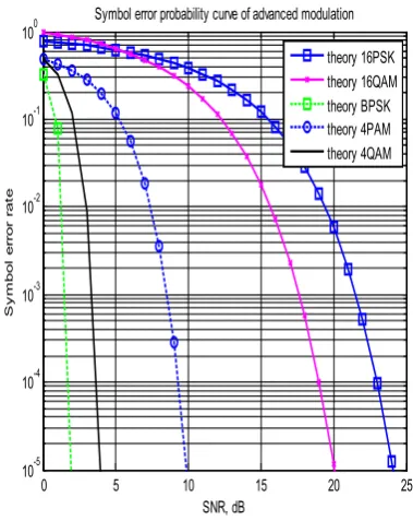
In digital communications, symbol rate is the number of symbol changes made to the transmission medium per second using a digitally modulated signal or a line code. The Symbol rate is measured in baud or symbols/second. In the case of a line code, the symbol rate is the pulse rate in pulses/second. Each symbol can represent or convey one or
[image:4.595.332.522.220.459.2]several bits of data. The symbol rate is related to, but should not be confused with, thegross bit rate expressed in bit/second. The symbol error rate of BPSK is lower compare to the 4-QAM. On the other hand symbol error rate of 4-QAM is lower than the 4-PAM. Similarly symbol error rate of 4-PAM is lower than that 16-QAM and symbol error rate of 16-QAM is lower than the 16-PSK. So we can conclude that if we can use BPSK modulation technique the symbol error rate is lower than all other method in this respect BPSK is best although it has many disadvantages also.
Figure 2. Comparison of symbol error rate
6. Conclusion
Without modulation the radiate power from transmitting antenna is not enough to transmit long distance. To increase the radiate power efficiency in wireless communication modulation is needed. But different modulation has different disadvantages and advantages in wireless communication system. Our interest to find the comparison between different advanced modulation techniques such as BSK, 4QAM, 4PAM, 4PSK, 16QAM, 16PSK system. The power required to represent large number of bits is greater than that of the lower number of bits. Therefore as the distance increase from the base station to the mobile station signal represent as lower number of bits. In other word greater the distance between the base stations to the mobile station, lower number of bit is required to represent the signal. Signal reconstruction in receiver is very difficult for many numbers of bits than the lower number bits. Therefore signal to noise ratio is lower value for large number of bits. From fig. 2 it is clear that bit error rate increasing from BSK to 4QAM to 4PAM to 4PSK to 16QAM to 16PSK for same signal to
0 5 10 15 20 25
10-5 10-4 10-3 10-2 10-1 100
SNR, dB
S
y
m
bol
er
ror
r
at
e
Symbol error probability curve of advanced modulation
noise ratio. This bit conversion is made by adaptive method with distance.For precise communication system symbol error rate should be lower value so in this purpose we can use BPSK modulation technique. The obtained results show that a significant improvements in terms of bit error rate (BER) and throughput can be achieved demonstrating the superiority of the BPSK modulation schemes compared to other transmission schemes.
REFERENCES
[1] X. Zhu and J. M. Kahn, “Free-space optical communication through atmospheric turbulence channels,” IEEE Trans. Commun., vol. 50, pp. 1293–1300, Aug. 2002.
[2] J. Li, J. Q. Liu, and D. P. Tayler, “Optical communication using subcarrier PSK intensity modulation through atmospheric turbulence channels,” IEEE Trans. Commun., vol. 55, pp. 1598–1606, Aug. 2007.
[3] W. Huang, J. Takayanagi, T. Sakanaka, and M. Nakagawa, “Atmospheric optical communication system using subcarrier PSK modulation,” IEICE Trans. Commun., vol. E76-B, pp.
1169–1177, Sep. 1993.
[4] S. G. Wilson, M. Brandt-Pearce, Q. Cao, and J. H. Leveque, “Free-space optical MIMO transmission with Q-ary PPM,” IEEE Trans. Commun., vol. 53, pp. 1402–1412, Aug. 2005. [5] W. Popoola and Z. Ghassemlooy, “BPSK subcarrier intensity
modulated free-space optical communications in atmospheric turbulence,” IEEE/OSA J. Lightwave Technol., vol. 27, pp. 967–973, Apr. 2009.
[6] N. D. Chatzidiamantis, A. S. Lioumpas, G. K. Karagiannidis, and S. Arnon, “Adaptive subcarrier PSK intensity modulation in free space optical systems,” IEEE Trans. Commun., vol. 59, pp. 1368–1377, May 2011.
[7] T. S. Rappaport, Wireless communicationsprinciples and practice, Prentice Hall, 2nd Edition,1998.
[8] Engineering, Arizona State University, Tempe, AZ 85287-5706, USA Received 11 January 2005; Revised 25 July 2005; Accepted 1 September 2005 .
[9] R. Alex. Panicker and Joseph M. Kahn, Fellow, IEEE, Algorithms for Compensation of Multimode FiberDispersion Using Adaptive Optics.