A Simple and Fast Line-Clipping Method as a Scratch
Extension for Computer Graphics Education
Dimitrios Matthes
,
Vasileios Drakopoulos
∗FacultyofSciences,DepartmentofComputerScienceandBiomedicalInformatics,Lamia,35131,CentralGreece,Greece
Copyright c2019 by authors, all rights reserved. Authors agree that this article remains permanently open access under the terms of the Creative Commons Attribution License 4.0 International License
Abstract
Line clipping is a fundamental topic in anintroductory computer graphics course. An understanding of a line-clipping algorithm is reinforced by having stu-dents write actual code and see the results by choosing a user-friendly integrated development environment such as Scratch, a visual programming language especially useful for children. In this article a new computation method for 2D line clipping against a rectangular window is introduced as a Scratch extension in order to assist computer graphics education. The proposed method has been compared with Cohen-Sutherland, Liang-Barsky, Cyrus-Beck, Nicholl-Lee-Nicholl and Kodituwakku-Wijeweera-Chamikara methods, with respect to the number of operations performed and the computation time. The performance of the proposed method has been found to be better than all of the above-mentioned methods and it is found to be very fast, simple and can be im-plemented easily in any programming language or integrated development environment. The simplicity and elegance of the proposed method makes it suitable for implementation by the student or pupil in a lab exercise.
Keywords
Computer Graphics Education, Line Clipping, Programming Education1
Introduction and Motivation
Research in Computer Graphics education occurs mainly around the two following topics: (a) pedagogy and practice of teaching Computer Graphics, or CG for short, and related technology, as well as (b) the setup of new and specific cur-ricula, often in relation with other curcur-ricula, such as art and design; see [20]. The proposition that CG is a form of intro-duction to computing in Further and Higher Education for stu-dents from Secondary Education with some knowledge of the subject is considered in [1].
Fundamental graphics techniques are a core topic in the computing body of knowledge. Teaching these techniques to today’s computer science or ICT pupils or students presents
a pedagogical challenge. Course critiques reveal student dis-satisfaction with the stale nature of theory presented without “live” examples; see [25]. Teaching computer graphics to se-condary education or undergraduate students seems to be more of a brain teaser by many instructors since there is a lot of mat-hematics involved in drawing even simple shapes. Students often tend to complain and discomfort, not only because of the advanced mathematic concepts they have to comprehend but also because they have to use a programming language to transform these concepts into graphics. As a result, instruc-tors often choose to use as simple concepts as possible and a user-friendly integrated development environment, or IDE for short.
As far as the IDE is concerned, Scratch usually serves as the introductory programming language for students to create interactive programs relatively easy and is used in schools wor-ldwide. Scratch is a free visual programming language develo-ped by the Lifelong Kindergarten group at the MIT Media Lab and is often used in teaching coding (see [4]), computer science and computational thinking. Its purpose is to aid young people, mainly for ages 8 and up, to learn programming. Instructors or educators may also use it as a tool across many other subjects including math, science, history, geography and art.
An activity for novice students involved in computer graphics design is line clipping. One purpose of this article is to describe a simple algorithm for 2D line clipping in Scratch which is faster than the existing ones. The algorithm derived from the need of eliminating lines in programming environ-ments where there are limitations of their graphical user inter-face, or GUI for short. The Scratch user interinter-face, for instance, is the environment of the Scratch program which divides the screen into several panes (Figure 1): From left to right, in the upper left area of the screen, there is astage area, featuring the results (i.e., animations, turtle graphics, etc., everything either in small or normal size, full-screen also available) and all spri-tes thumbnails listed in the bottom area. The stage usesxand
ycoordinates, with 0,0 being the stage center. The stage is 480 pixels wide and 360 pixels tall, x : 240being the far right,
x:−240being the far left,y: 180being the top, andy:−180
being the bottom; see Figure 2.
pro-Figure 1.Scratch 2.0 development environment and its different areas at star-tup.
Figure 2.Scratch screen coordinates.
grammer decides to draw a line out of the stage area, there is no way to do that with the tools available. On this stage, the programmer can move sprites or draw objects using the pen. Scratch as well as many other programming languages doesn’t allow to the sprites or to the pen to exceed the screen limits. For example, if a programmer wants to draw a very long line that goes beyond these limits, there is no option to override this limitation with the current commands/tiles. The solution to this problem comes with the line-clipping technique.
This article has the following structure. In Section 2 the line clipping as well as the corresponding algorithms are presen-ted. Section 3 presents the proposed line-clipping algorithm together with some comments and remarks on their implemen-tation in Scratch, Section 4 presents the results after comparing the proposed algorithm with five other line clipping algorithms (Cohen-Sutherland, Liang-Barsky, Cyrus-Beck, Nicholl-Lee-Nicholl and Kodituwakku-Wijeweere-Chamikara) in Scratch together with a lesson plan implemented for teaching line clip-ping in secondary education, Section 5 discusses the advanta-ges and disadvantaadvanta-ges of the methods and, finally, Section 6 presents the conclusions that derive from the study and the use of the algorithm in practice as well as suggestions for impro-vement.
2
On Line Clipping
In computer graphics, any procedure that eliminates those portions of a picture that are either inside or outside a specified region of space is referred to as aclipping algorithmor simply
[image:2.595.327.528.239.315.2]clipping. The region against which an object is to be clipped is called aclipping object. In two-dimensional clipping, if the clipping object is an axis-aligned rectangular parallelogram, it is often called theclipping windoworclip window. Usually a clipping window is a rectangle in standard position, although we could use any shape for a clipping application. For a three-dimensional scene it is called aclipping region; see [8].
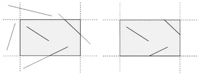
Figure 3.Region before (left) and after (right) 2D line clipping.
Line clippingis the process of removing lines or portions of lines outside an area of interest. Typically, any line or part the-reof which is outside of the viewing area is removed (Figure 3). Most of the times, this process uses mathematical equations or formulas for removing the unecessary parts of the line. The programmer draws only the part of the line which is visible and inside the desired region by using, for example, the slope-intercept formy=mx+b, wheremis the slope or gradient of the line,bis they-intercept of the line andxis the independent variable of the functiony =f(x)or just the vector equation. The most common application of clipping is in the viewing pipeline, where clipping is applied to extract a designated por-tion of a scene (either two-dimensional or three-dimensional) for display on an output device. Clipping methods are also used to antialias object boundaries, to construct objects using solid-modeling methods, to manage a multiwindow environ-ment, and to allow parts of a picture to be moved, copied, or erased in drawing and painting programs; see for example [7] or [3].
2.1
Existing MethodsThere are four primary algorithms for line clipping: Cohen-Sutherland, Cyrus-Beck [2], Liang-Barsky [12] and Nicholl-Lee-Nicholl [15]. Over the years, other algorithms for line clipping appeared, like Fast Clipping [24], Skala [21] [22] [23], Ray [19], but many of them are variations of the first two ones [18]. In general, the existing line-clipping algorithms can be classified into three types: the encoding approach (with the Cohen-Sutherland algorithm as a representative), the parame-tric approach (with the Liang-Barsky and the Cyrus-Beck gorithms as representatives) and the Midpoint Subdivision al-gorithms.
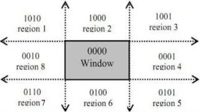
[image:2.595.67.269.290.440.2]in which the line resides is divided into nine regions. The al-gorithm determines first in which regions the two points that define the line are in and then performs complete, partial or no drawing of the line at all; see for example [5], p. 113 or [6] (Figure 4). The method that is used to decide, if a line is
suit-Figure 4.The nine regions of the Cohen-Sutherland algorithm in the 2D space.
able for clipping or not, performs logical AND operation with the region codes of the line endpoints. After the logical AND, if the result is not 0000, the line is completely outside the clip-ping region [9]. The implementation of the Cohen-Sutherland algorithm in Scratch requires a relatively large number of com-parisons for determining the regions. In addition, it requires many bitwise AND operations but this kind of operation is not embedded in Scratch. This technique is also referred to as En-coding and Code Checkingin [13].
The method of Mike Cyrus and Jay Beck is a general line-clipping algorithm, but it introduces extra floating point opera-tions for determining the value of a parameter corresponding to the intersection of the line to be clipped with each window edge [10]. It is ofO(N)complexity and is primarily inten-ded for clipping a line in the parametric form against a convex polygon in two dimensions or against a convex polyhedron in three dimensions.
Midpoint subdivision algorithm is an extension of the Cyrus-Beck algorithm and follows a divide and conquer strategy. It is mainly used to compute visible areas of lines that are pre-sent in the view port are of the sector or the image. It follows the principle of the bisection method and works similarly to the Cyrus-Beck algorithm by bisecting the line into equal hal-ves. But unlike the Cyrus-Beck algorithm, which only bisects the line once, Midpoint Subdivision Algorithm bisects the line numerous times. The Midpoint Subdivision algorithm is not efficient unless it is implemented in hardware.
[image:3.595.66.264.161.272.2]On the other hand, You-Dong Liang and Brian Barsky have created an algorithm that uses floating-point arithmetic for fin-ding the appropriate end points with at most four computations [16]. This algorithm uses the parametric equation of the line and solves four inequalities to find the range of the parameter for which the line is in the viewport [12]. The method of Liang-Barsky is very similar to Cyrus-Beck line-clipping algorithm. The difference is that LiangBarsky is a simplified Cyrus-Beck variation that was optimised for a rectangular clip window. In general, the Liang-Barsky algorithm is more efficient than the Cohen-Sutherland line-clipping algorithm. However, the algo-rithm in its implementation in Scratch requires also a relatively large number of comparisons so it is not very efficient after all.
Figure 5.Defining the line for clipping with the Liang-Barsky algorithm.
The Nicholl-Lee-Nicholl algorithm is a fast line-clipping al-gorithm that reduces the chances of clipping a single line seg-ment multiple times, as may happen in the Cohen–Sutherland algorithm. The clipping window is divided into a number of different areas, depending on the position of the initial point of the line to be clipped.
In 2013, a fast line clipping algorithm with slightly dif-ferent approach from the above ones was introduced by Kodituwakku-Wijeweere-Chamikara [11]. It is newer and per-forms better than the Cohen-Sutherland and Liang-Barsky al-gorithms. It checks every boundary of the clipping area (top, bottom, left, right) and performs line clipping by using the equation of the line. Moreover, it checks if the line segment is just a point or parallel to principle axes.
2.2
CG Teaching ApproachAlthough instructors can choose among the line-clipping al-gorithms mentioned above, they would find themselves in a po-sition of discarding some of them as they prove to be unsuitable for teaching, especially in lower education levels. If we add the parameter of performance, then we would find that there might be a need for a new simple but faster algorithm for line clip-ping to overcome the drawbacks of the existing algorithms that could be used in educational context. Having this in mind, we experimented on implementing line clipping by using the ex-isting algorithms in Scratch, so as to choose the most effective one for teaching. The results will be described in detail in the following sections.
complicated to be taught in secondary education, since stu-dents knowledge of mathematics is not advanced enough. The Nicholl-Lee-Nicholl algorithm, although it is simple and easy to comprehend, has an extended code listing and is rather slow in execution. The Kodituwakku-Wijeweere-Chamikara algo-rithm is easier to implement but harder to be taught because it uses many conditions and comparisons (if..then..else.. state-ments) and thus is difficult for students to code it.
The difficulties of the previous line-clipping algorithms in Scratch seem to be overcomed by the proposed algo-rithm. Although it uses the main concept of the Kodituwakku-Wijeweere-Chamikara algorithm, it avoids many unnecessary comparisons, like the parallel lines or the dots. It aims at sim-plicity and speed and does only the necessary calculations in order to determine whether the beginning as well as the end of the line are inside the clipping region. Moreover, the source code listing is very short.
3
Materials and Methodology
3.1
Methodology
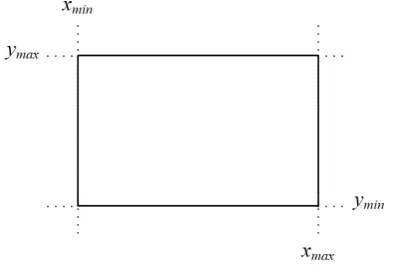
Assume that we want to clip a line inside a rectangle re-gion or window that is defined by the points(xmin, ymax)and
[image:4.595.66.263.411.547.2](xmax, ymin). This region is depicted in Figure 6. Given two
Figure 6.Line clipping region.
points(x1, y1)and(x2, y2)on the line that we want to clip, the
slopemof the line is constant and is defined by the ratio
m= y2−y1
x2−x1
. (1)
For an arbitrary point(x, y)on the line, the previous ratio can be written as
m= y−y1
x−x1
.
Solving fory
y−y1=m·(x−x1)⇔y=y1+m(x−x1).
By replacingmin this equation with (1)
y=y1+
y2−y1
x2−x1
·(x−x1). (2)
Solving forx, the equation becomes
x=x1+
x2−x1
y2−y1
·(y−y1). (3)
Equations (2) and (3) are two mathematical representations of the line equationy = mx+band will be used later by the algorithm in order to determine the part of the line that is inside the clipping window.
3.2
The basic steps
Suppose that the line which has to be clipped is defined by the points(x1, y1)and(x2, y2).
Step 1: The first step of the algorithm checks, if both points are outside the line-clipping window and at the same time in the same region (top, bottom, right, left). If one of the following occurs then the entire line is being rejected and the algorithm draws nothing (see Figure 7):
x1< xminANDx2< xmin(line is to the left of the clipping
window)
x1 > xmax AND x2 > xmax (line is to the right of the
clipping window)
y1 < yminANDy2 < ymin(line is under the clipping
win-dow)
y1 > ymax ANDy2 > ymax(line is over the clipping
win-dow)
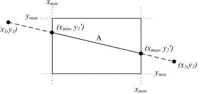
Figure 7. LinesA, B, C, Dare rejected according to the first step of the
algorithm.
Step 2: In the second step, the algorithm compares the coordi-nates of the two points along with the boundaries of the clip-ping window. It compares each of the x1 andx2
coordina-tes with thexminandxmaxboundaries respectively, as well as
each one of they1andy2coordinates with theyminandymax
boundaries. If any of these coordinates are out of bounds, then the specific boundary is used in the equation that determines the line in order to achieve clipping (see Figure 8).
For each of the coordinates of the two points and according to (2) and (3), the comparisons and changes made are:
• Ifxi< xminthen
xi=xmin
yi=y1+
y2−y1
x2−x1
[image:4.595.327.527.420.564.2]Figure 8.Selecting the points of the line that are inside the clipping area.
• Ifxi> xmaxthen
xi=xmax
yi=y1+
y2−y1
x2−x1
·(xmax−x1)
• Ifyi< yminthen
yi=ymin
xi =x1+
x2−x1
y2−y1
·(ymin−x1)
• Ifyi> ymaxthen
yi=ymax
xi=x1+
x2−x1
y2−y1
·(ymax−x1)
wherei= 1,2.
Step 3: The third and final step checks if the new points, after the changes, are inside the clipping region and if so, a line is being drawn between them.
3.3
The algorithm in pseudo-code
The representation of the algorithm in pseudo-code follows:
/ / x1 , y1 , x2 , y2 , xmin , ymax , xmax , ymin / /
i f n o t ( x1<xmin and x2<xmin ) and n o t ( x1>xmax and x2>xmax ) t h e n i f n o t ( y1<ymin and y2<ymin ) and n o t ( y1>ymax and y2>ymax ) t h e n
x [ 1 ] = x1 y [ 1 ] = y1 x [ 2 ] = x2 y [ 2 ] = y2 i =1 r e p e a t
i f x [ i ]<xmin t h e n x [ i ] = xmin
y [ i ] = ( ( y2−y1 ) / ( x2−x1 ) )∗( xmin−x1 ) + y1 e l s e i f x [ i ]>xmax t h e n
x [ i ] = xmax
y [ i ] = ( ( y2−y1 ) / ( x2−x1 ) )∗( xmax−x1 ) + y1 end i f
i f y [ i ]<ymin t h e n y [ i ] = ymin
x [ i ] = ( ( x2−x1 ) / ( y2−y1 ) )∗( ymin−y1 ) + x1 e l s e i f y [ i ]>ymax t h e n
y [ i ] = ymax
x [ i ] = ( ( x2−x1 ) / ( y2−y1 ) )∗( ymax−y1 ) + x1 end i f
i = i + 1 u n t i l i>2
i f n o t ( x[1]<xmin and x[2]<xmin ) t h e n i f n o t ( x[1]>xmax and x[2]>xmax ) t h e n
d r a w L i n e ( x [ 1 ] , y [ 1 ] , x [ 2 ] , y [ 2 ] ) end i f
end i f end i f end i f
4
Results and Evaluation
[image:5.595.51.249.230.436.2]The number 100,000 was selected as the number of lines to be clipped during the evaluation. Scratch is capable of drawing 100,000 lines in an average time of 10 seconds, depending on the system. The lines were created by each algorithm in every execution and clipped accordingly. The results are shown in Table 1.
Table 1. Execution times of each algorithm when creating 100,000 lines in
Scratch
Exec. CS LB CB NLN KWC Prop. (sec) (sec) (sec) (sec) (sec) (sec)
1 44.349 11.848 19.607 19.807 9.910 6.021 2 44.098 11.501 1.425 1.376 1.224 6.050 3 43.910 11.557 1.471 1.437 1.196 6.038 4 44.018 11.562 1.530 1.446 1.271 6.022
5 44.248 1.263 1.519 1.455 1.297 1.151
6 44.033 1.233 1.418 1.505 1.268 1.216
7 44.120 1.182 1.439 1.427 1.275 1.076
8 43.888 1.205 1.658 1.332 1.223 1.209
9 43.988 1.218 1.423 1.448 1.217 1.214
10 44.141 1.272 1.462 1.450 1.251 1.199 Avg: 1.365 1.256 1.479 1.445 1.244 1.165
Preparation
In order to determine the efficiency of the proposed algo-rithm we decided to compare it with the five others: Cohen-Sutherland, Liang-Barsky, Cyrus-Beck, Nicholl-Lee-Nicholl and Kodituwakku-Wijeweere-Chamikara.
Scratch’s programming environment is advantageous in comparison to other environments for the following reasons: a) Scratch has a built-in display area where the visual result of the algorithm can be viewed directly, b) it has embedded timer and time commands which make the measurement of the exe-cution time easy, c) the algorithm is accessible to everyone via the Internet, d) it allows users to temporarily interfere with the algorithm for experimentation.
The experiment
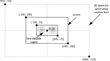
Figure 9.Defining the 2D space for creating random line as well as definition of the line clipping window.
The time that each algorithm needs to clip and draw this large number of lines is recorded in every execution. The whole process is repeated 10 times and at the end the average time is being calculated.
Hardware and software specifications
For realistic results, an average computer system was used for the experiment. The hardware as well as the software spe-cifications were: a) Intel Core2Duo @ 2.60GHz CPU, b) RAM 2GB, c) AMD Radeon HD 5450 GPU, d) Windows 10 Profes-sional operating system, e) Scratch 2.0.
The Implemented Lesson Plan
As far as the educational procedure is concerned, the pro-posed algorithm turned out to be a real asset in the classroom for the ICT teacher. It is simple, easy to comprehend and can undoubtedly be taught to students in secondary education.
Students prerequisite knowledge is the equation of a straight line and basic programming experience in using variables in Scratch. Students become familiar with the first in early secon-dary school years. As for the latter, they already have expe-rience in Scratch programming during informatics course. In other words, this knowledge is already mastered by senior se-condary school students.
One of the basic problems we encounter today is traditional attitudes and methods depending on an educational sense of rote learning. Such teaching attractive methods activating stu-dents by taking them in the centre should be preferred instead of usual teacher centred educational methods and techniques. So we have used student-centred learning followed by inquiry-based learning. We implemented the following lesson plan in the second class of a senior high school (students age 16-17) as part of the thematic sub-module ‘multimedia’ with 23 pu-pils in the classroom. The lesson took place in our Computer Lab having twelve PCs for students and one PC for the tea-cher. The time required to complete the lesson is 45 minutes. The required materials are a projector, an internet connection, a whiteboard and a marker.
Instruction (3 minutes)
Firstly, the teacher asks the students to create a new sprite of dimension 1×1 pixels. Students work in groups of two
persons. Then, their assignment is to create a script and, by using the Pen, to plot three noncollinear points within the stage and draw a triangle having these points as vertices.
Second activity (4 minutes)
The next activity for the students is to determine three new noncollinear points outside the borders of the stage, so as to draw a new triangle having these points as vertices. Students have enough time to experiment and they are expected to con-clude that no matter how much they tried, they could not ex-ceed the boundaries of the stage. The conclusion is the same for all teams: the triangle cannot have any vertex outside the window area.
Presentation (8 minutes)
The teacher initiates a discussion between all groups explai-ning Scratch programming restrictions and limitations. The discussion will gradually lead to recognising the need for line clipping. The teacher explains the new term and demonstra-tes how line clipping looks like. So, he runs the Scratch pro-gram executing the line-clipping algorithm to show students what they will soon build.
Development (7 minutes)
Next, the teacher reminds the class of the slope-intercept form of a line and how we can implement it on the plane. If necessary, he/she also reminds them of how to create variables in Scratch.
Generalising (8 minutes)
The teacher introduces the proposed line-clipping algorithm to the class as a solution to the problem of drawing the triangle, since the lines can be clipped and the rest of the triangle can be drawn correctly within the limits of the design area.
Application (12 minutes)
Students are now ready to work on their PC and solve the initially given problem by applying the new concept. The code for line clipping is given to them as a ready-to-use tool. Once they manage to solve the problem with three lines, we ask them to solve the same problem with four or five lines (square or pentagon).
Recapitulation (3 minutes)
Finally, students are asked to answer a short online question-naire, so that the teacher can get feedback from them in order to determine, whether the lesson was successful or not.
5
Performance and Discussion
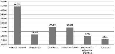
reviewing the results, we notice that the proposed algorithm is about seven times faster than the Cohen-Sutherland algo-rithm, almost two times faster than the Liang-Barsky, about three times faster than both the Cyrus-Beck and the Nicholl-Lee-Nicholl and, finally, one and a half times faster than the Kodituwakku-Wijeweere-Chamikara.
Figure 10. Graph with the average time of each algorithm in Scratch (from
lower to higher value).
As mentioned before, each algorithm has advantages and disadvantages. The Cohen-Sutherland algorithm is the oldest of all algorithms, it has an average performance comparing to the other four but it is difficult to implement due to the bitwise AND operations that it requires. Scratch does not have em-bedded commands (tiles) for bitwise logic so the programmer has to create special functions for this purpose. Unfortunately, these functions require a lot of calculations and make the algo-rithm remarkably slower.
The Liang-Barsky algorithm looks steady in its performance and is definitely faster than the Cohen-Sutherland algorithm. Liang-Barsky’s main drawback is that it is slightly more diffi-cult than the others to understand since it contains more advan-ced mathematical concepts.
The Cyrus-Beck algorithm also uses advanced mathematical concepts, which makes it too complicated to be taught in se-condary education, since students knowledge of mathematics is not advanced enough.
The Nicholl-Lee-Nicholl algorithm, though simple and easy to comprehend, has an extended code listing and is rather slow in execution.
Finally, the Kodituwakku-Wijeweere-Chamikara algorithm is the second fastest algorithm, but it uses a lot of conditions which make the algorithm more complicated and thus slightly slower than the proposed one.
6
Conclusions
There are many line-clipping algorithms in computer graphics. Each one has advantages and disadvantages. The afore-mentioned experimental results indicate that the propo-sed algorithm is simpler, faster and it certainly performs better than other known 2D line-clipping algorithms. It is capable of using only a very small number of variables and it is very easy to implement in any programming language or IDE. An inte-resting extension of this algorithm would be clipping in three dimensions; see [17].
Acknowledgements
An earlier version, written in Greek, of the proposed method in Scratch was published in the 9th Conference on Informa-tics in Education 2017 which took place in the University of Piraeus in Greece [14].
REFERENCES
[1] C. K. Clutterbuck and T. Ishwarwood. Computer graphics as an introduction to computing. International Journal of Mathematical Educational in Science and Technology, 5(3–4):463–470, 1974.
[2] M. Cyrus and J. Beck. Generalized two- and three-dimensional clipping.Comput. Graph., 3:23–28, 1978. [3] S. C. Dimri. A simple and efficient algorithm for line and
polygon clipping in 2-d computer graphics.International Journal of Computer Applications, 127(3):31–34, 2015. [4] V. Drakopoulos. Fractal-based image encoding and
com-pression techniques. Commun. – Scientific Letters of the University of ˇZilina, 15(3):48–55, 2013.
[5] J. D. Foley, A. van Dam, S. K. Feiner, and J. F. Hughes.
Computer Graphics Principles and Practice. Addison-Wesley, Reading, MA, 2nd edition, 1990.
[6] Atul P. Godse and Deepali A. Godse. Computer Graphics. Technical Publications Pune, 2001.
[7] D. Hearn and M. P. Baker.Computer Graphics C Version. Prentice Hall, 2nd edition, 1997.
[8] D. Hearn, M. Pauline Baker, and W. R. Carithers. Compu-ter Graphics with Open GL. Pearson Education Limited, Edinburgh Gate, Harlow, Essex CM20 2JE, 4th edition, 2014.
[9] M. S. Iraji, A. Mazandarami, and H. Motameni. An effi-cient line clipping algorithm based on Cohen-Sutherland line clipping algorithm. American Journal of Scientific Research, 14:65–71, 2011.
[10] S. Kaijian, J. A. Edwards, and D. C. Cooper. An efficient line clipping algorithm.Comput. Graph., 14(2):297–301, 1990.
[11] S. R. Kodituwakku, K. R. Wijeweera, and M. A. P. Cha-mikara. An efficient algorithm for line clipping in com-puter graphics programming. Ceylon Journal of Science (Physical Sciences), 1(17):1–7, 2013.
[12] Y-D. Liang and B. A. Barsky. A new concept and method for line clipping. tog, 3(1):1–22, 1984.
[14] D. Matthes and K. Kappas. A simple and fast algorithm for line clipping in scratch. In N. Alexandris, P. Vlamos, Ch. Douligeris, and V. Belesiotis, editors,9th Conference on Informatics in Education 2017, pages 14–26, 2017. [15] Tina M. Nicholl, D.T. Lee, and Robin A. Nicholl. An
effective new algorithm for 2-d line clipping: Its deve-lopment and analysis. Comput. Graph., 21(4):253–262, 1987.
[16] Nisha. Comparison of various line clipping algorithms: Review. International Journal of Advanced Research in Computer Science and Software Engineering, 7(1):68– 71, 2017.
[17] Nisha. A review: Comparison of line clipping algorithms in 3d space.International Journal of Advanced Research, 5(1):2377–2379, 2017.
[18] A. Pandey and S. Jain. Comparison of various line clip-ping algorithms for improvement. International Journal of Modern Engineering Research, 3(1):69–74, 2013. [19] B. K. Ray. A line segment clipping algorithm in 2d.
In-ternational Journal of Computer Graphics, 3(2):51–76, 2012.
[20] B. Sousa Santos, J.-M. Dischler, V. Adzhiev, E.F. An-derson, A. Ferko, O. Fryazinov, M. Ilˇc´k, I. Ilˇc´kov´a, P. Slavik, V. Sundstedt, L. Svobodova, M. Wimmer, and J. Zara. Distinctive approaches to computer graphics edu-cation.Computer Graphics Forum, 37(1):403–412, 2018. [21] V. Skala. An efficient algorithm for line clipping by
con-vex polygon.Comput. Graph., 17(4):417–421, 1993. [22] V. Skala. O(lgn) line clipping algorithm ine2. Comput.
Graph., 18(4):517–524, 1994.
[23] V. Skala. A new approach to line and line segment clipping in homogeneous coordinates. Visual Comput, 21:905–914, 2005.
[24] M. S. Sobkow, P. Pospisil, and Y. Yang. A fast two-dimensional line clipping algorithm via line encoding.
Comput. Graph., 11(4):459–467, 1987.