© 2016, IRJET | Impact Factor value: 4.45 | ISO 9001:2008 Certified Journal | Page 756
Image Forgery and it’s Detection Technique: A Review
Varsha Sharma, Swati Jha , Dr. Rajendra Kumar Bharti Dept. of Computer Science and Engineering, BTKIT, Dwarahat, INDIA
---***---Abstract-Image forgery detection is emerging as one of the hotresearch topic among researchers in the area of image forensics. Many techniques have been suggested to detect such type of forgery with the original image, but the problem is not being solved. Some issues still remained either unsolved. Block matching algorithm or block tiling algorithm is the most commonly used method to detect the duplication in the image. One of the major challenges is the time complexity of such algorithms. In the proposed method this issue has been addressed without compromising the quality of the method. Discrete Cosine Transform (DCT) is used to represent the features of overlapping blocks.
Keywords—Image Forgery, Copy move forgery detection techniques; DCT based algorithm; passive forgery detection
I. INTRODUCTION
Digital Image forensics is an emerging branch of image processing, which is aimed at obtaining quantitative evidence on the origin and truthfulness of a digital image[1][5] .One of the principal tasks of image forensics is image tampering detection. Tampering means to interfere with something in order to cause damage or make unauthorized alterations. Images are treated as proofs in various scenarios and thus image tampering is defined as intentional manipulation of images for malicious purposes [2]. Image tampering dates its origin to the earliest twentieth century when it was used for political propaganda. image tampering is not a rare phenomenon and as a result the last decade marked tremendous developments in the field of image forensics techniques.
Image forensics techniques can be classified under two different approaches, Active approaches and Passive/Blind approaches [3]. Active approaches were used traditionally by employing data hiding (watermarking) or digital signatures.
Passive approaches or blind forensic approaches use image statistics or content of the image to verify its genuineness [5].Now days, digital images are widely used all over the world. Exchanging soft copy of various documents is a normal practice in these days. So there is a possibility of forgery while exchanging such type of documents. Image Forgery is the process of making illegal changes of image information. Forgery may occur in applications which uses digital image because user can change it by using editing tools available in market.
Areas of application
• Authentication of images captured from CCD (charge coupled device) cameras
• Authentication of information available in an image
• Authenticity of evidences
• Fingerprint recognition
• Document authentication
© 2016, IRJET | Impact Factor value: 4.45 | ISO 9001:2008 Certified Journal | Page 757 Fi
g1.An example of copy-move forgery:(a) the forged image with four missiles & (b) the original image with three missiles.
II. CLASSIFICATION OF IMAGE FORGERY TECHNIQUES:
Fig.2. Classification of Image forgery Techniques
A. Active Approach
In active approach, the digital image requires some kind of pre-processing such as watermark embedded or signatures are generated at the time of creating the image. However, in practice this would limit their application. Digital watermarking [4] and signature are two main active protection techniques, as something embedded into images
when they are obtained. We can detect the Image is tampered, if special information cannot be extracted from that obtained image. Watermarking is such a method of active tampering detection, as a security structure is embedded into the image, but most present imaging devices do not contain any watermarking or signature module and that are similar to the application of active protection. This structure is used for integrity evaluation in the sense that if any discrepancy is found with the structure then the image is tampered and an inverse analysis over the structure is done to locate tampered Regions of the image.
In recent times, various schemes are proposed for providing security to the image, which is analogous to concept of watermarking like, message authentication code, image hash, image checksum and image shielding as a counter part to it.
B. Passive Approach
© 2016, IRJET | Impact Factor value: 4.45 | ISO 9001:2008 Certified Journal | Page 758 III. TYPES OF IMAGE FORGERY
A. Image Retouching:
Image Retouching is considered as less harmful kind of digital image forgery than other types present. In case of image retouching original image does not significantly changes, but there is enhancement or reduces certain feature of original image. This technique is popular among magazine photo editors they employ this technique to enhance certain features of an image so that it is more attractive. Actually, the fact is that such enhancement is ethically wrong.
B. Image splicing or photomontage:
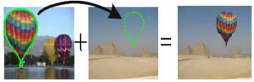
[image:3.612.323.573.234.320.2]This technique for making forgery images is more aggressive than image retouching. Image splicing is fundamentally simple process and can be done as crops and pastes regions from the same or separate sources. This method refers to a paste-up produced by sticking together images using digital tools available such as Photoshop. In Image Splicing technique there is composition of two or more images, which are combined to create a fake image. Examples include several infamous news reporting cases involving the use of faked images. Below shows how to create forge Image; by copying a spliced portion from the source image into a target image, it is a composite picture of scenery which is forge image.
Fig.3.Example of Image splicing
C. Copy-Move Attack:
The copy move forgery is popular as one of the difficult and most commonly used kind of image tampering technique. In
[image:3.612.37.288.563.644.2]this technique, one needs to cover a part of the image in order to add or remove information. In the Copy-Move image, manipulation technique a part of the same image is copied and pasted into another part of that image itself. In a copy-move attack, the intention is to hide something in the original image with some other part of the same image [8]. The example of Copy-Move type is as shown below.
Fig 4. Is an example of copy-move forgery where a group of soldiers are duplicated to cover George Bush. Hence, the goal in detection of copy-move forgeries is to detect image areas that are same or extremely similar.
IV. PROPOSED METHOD
A). ALGORITHM STRUCTURE
The proposed method uses the DCT coefficients to represent the overlapping block. The DCT coefficients are ordered in zigzag manner to keep the low frequency coefficients together and before the high frequency coefficients in the row vector. According to the framework shown in Fig. 5, the proposed algorithm works as follows.
(1) The input image is a gray scale image ‘I’ of the size mx n. If it is a color image, it can be converted to a gray scale image using the standard formula, I = 0.299R + 0.587G +0.114B. RGB represents the three color components of RGB color model.
© 2016, IRJET | Impact Factor value: 4.45 | ISO 9001:2008 Certified Journal | Page 759 (3) Apply DCT to every block and reshape the b x b quantized
coefficient matrix to a row vector by ordering DCT coefficients in zigzag order. To reduce the size of the vector and to retain only low frequency coefficients, the vector is truncated to only p x b2 elements to retain only low frequency coefficients. The parameter ‘p’ decides the number of coefficients retained.
(4) All vectors are sorted lexicographically and form a (mb+1) (n-b +1) x pb2 matrix ‘A’.
(5) For each row ai in ‘A’, test its neighboring rows aj which satisfy the condition that the first ‘q’ quantized DCT coefficients are same. As these DCT coefficients are sufficient to represent the major intensity distribution over the block. (6) If ai and aj come out to be similar, the distance between two should be more than the block size i.e. ‘b’.
(7) If distance between similar blocks is greater than’ b’, then calculate the shift vector‘s’ and increase the count for ‘s’. Where s= (s1, s2) = (i1-j1, i2-j2) where similar block coordinates are (i1, j1) and (i2, j2).
(8) The highest count of ‘s’ is taken to be threshold frequency. Also, it should be more than b x b to represent some significant duplication.
(9) For all the blocks having shift value greater than threshold value, mark the regions in the image with red color to represent copy moved regions.
Fig.5 Algorithm framework
a). CALCULATIONS OF DCTALGORITHM:
The DCT Equations:
The DCT equation represents the i, j entry of the DCT of an image.
…. .(1)
To get the matrix form of equation (1), we will use the following equations.
© 2016, IRJET | Impact Factor value: 4.45 | ISO 9001:2008 Certified Journal | Page 760 Firstly, we start with 8*8 block of image pixel values that is
selected from very uppermost left side corner of an image. For DCT, pixel values ranging from -128 to 127.Therefore from each pixel values of 8*8 blocks 128 gets subtracted. After subtraction ,this result is stored into some alphabet let say M. Now, we perform the DCT which is completed successfully by matrix multiplication.
D=T*M*T’
b). QUANTIZATION:
Now, above DCT matrix is ready for compression by quantization. In this step, by selecting a specific quantization matrix it is possible to vary the levels of image compression and quality of an image. The image quality level ranging from 1 to 100 where 1 gives lower image quality and higher compression while 100 gives better quality but lower compression. The quality level Q50 matrix gives both high compression and best decompression image quality.
For quantization, it is obtained by dividing each element in D matrix by corresponding pixel values in the Q50 matrix and round up to the nearest integer value.
c).CODING:
The quantized matrix C is now used for final step of compression. In this step all coefficients of C are converted into binary stream by using encoder. After quantization most of the coefficients results into zero.JPEG encode these quantized coefficients in the zig-zag manner as shown in figure.
Fig.6 process of coding
B).ANALYSIS OF METHOD:-
© 2016, IRJET | Impact Factor value: 4.45 | ISO 9001:2008 Certified Journal | Page 761 coefficients are exploited. The high frequency coefficients are
susceptible to noise, so the row vectors are truncated. Further first few coefficients represent the major intensity distribution of the block [11]. Therefore the low frequency coefficients must be either same or should be very close for the copy moved regions. Only the blocks satisfying this condition are used further to update the frequency count and hence the numbers of potential similar blocks are significantly reduced. Another modification is to get rid of the manual setting of some thresholds. First one is the threshold for number of neighboring row vectors (Nn) tested for similarity. Due to the use of stricter similarity criteria there is hardly any need for this parameter. Another is the threshold for minimum distance between matching blocks (Nd). Experiments have shown that it can be taken as the size of the block as it will avoid the neighboring overlapping blocks to be tagged as similar. Larger threshold has a risk of missing potential similar blocks. So it has been fixed to ‘b’. Lastly the threshold count for valid shifts (Nf) will also vary from image to image and hence difficult to set prior to applying on arbitrary image. A more intelligent approach is being suggested. The maximum frequency of shift vectors is taken as threshold frequency as this will be corresponding to the largest cluster of similar blocks. To detect multiple duplicated regions lower value may be considered. A minimum of b x b shift frequency should be there to represent at least single block redundancy. However, in some cases of post processing operations of rotation and scaling lowering the threshold may help. Experimental results have confirmed a marked improvement in the execution time compared with theexisting method.
V. EXPERIMENTAL RESULTS
ORIGINAL IMAGE FORGE IMAGE OUTPUT IMAGE
ORIGINAL IMAGE FORGE IMAGE OUTPUT IMAGE
VI. CONCLUSION
In this paper, we studied that, due to the advancement in the digital software’s manipulation of digital images has become easy. As powerful computers, advanced photo-editing software packages and high resolution capturing devices are invented. We studied the different types of image forgery as it is the vital need to make trust in all images and photographs we further studied the technique for detection of any kind of Image forgery, which are based on different approaches.
The proposed method has addressed the issue successfully and is considerably faster than the existing method. It has detected forgery with good success rate in the image dataset. Also, it has shown robustness against
Added Gaussian noise, JPEG compression and small amount of scaling and rotation.
REFERENCES:
© 2016, IRJET | Impact Factor value: 4.45 | ISO 9001:2008 Certified Journal | Page 762 [2] Gajanan K. Birajdar, Vijay H. Mankar, “Digital image
forgery detection using passive techniques: A survey,” Digital Investigation, vol. 10, no.3, 2013, pp. 226-245.
[3] S. Kumar, P. Das, and S. Mukherjee, “Copy-Move Forgery Detection in Digital Images: Progress and Challenges,” International Journal on computer Science and Engineering, vol. 3, no. 2, 2011, pp. 652-663.
[4] O. M., Al-Qershi and B. E. Khoo, “Passive detection of copy-move forgery in digital images: State-of-the-art,” Forensic Science International, vol. 231, no. 1, 2013, pp. 284– 295.
[5] J. Fridrich, D. Soukalm, J. Luka ´s ˇ, “Detection of copy-move forgery in digital images,” Digital Forensic Research Workshop, Cleveland, OH, 2003, pp. 19–23.
[6] A.C. Popescu, H. Farid, “Exposing Digital Forgeries By Detecting Duplicated Image Regions,” Tech. Rep. TR2004-515, Dartmouth College, 2004.
[7] Ashima Gupta, Nisheeth Saxena, S.K Vasistha, “Detecting copy move forgery using DCT”, International Journal of Scientific and Research Publications, Volume 3, Issue 5, May 2013 1 ISSN 2250-3153 .
[8] B. Mahdian and S. Saic, “Detection of copy-move forgery using a method based on blur moment invariants,” Forensic science international, vol. 171, no. 2, 2007, pp. 180–189. [9] K. S. Bacchuwar and K. Rama krishnan, “A Jump Patch-Block Match Algorithm for Multiple Forgery Detection,” International Multi-Conference on Automation, Computing, Communication, Control and Compressed Sensing,2013, pp. 723-728.
[10] R.C. Gonzalez, R.E. Woods, “Digital Image Processing”, 2nd edition, Addison- Wesley, 2003.