© 2016, IRJET | Impact Factor value: 4.45 | ISO 9001:2008 Certified Journal | Page 882
REDUCTION OF LINE LOSS BY USING UPFC IN ISOLATED SUBSTATIONS
AND MULTIPLE LOOP DISTRIBUTION SYSTEMS
M. Sushmi
1, M. Ramasekhar Reddy
21
M.Tech Student, Dept. of EEE, JNTU
–
Anantapuramu, India
,
[email protected]
2Asst. Prof. & Head Inc., Dept. of EEE, JNTUACE, Kalikiri, India, [email protected]
---***---
Abstract -The production and usage of electricity are changing by considering the impact of electricity systems on environment. Customers are looking for uninterrupted and reliable power supply. Network reconfiguration of radial systems to loop systems will minimize the voltage drop and power interruptions. The looping of systems will result in introduction of loop currents that causes additional losses in the system. Power system utilities are focused on incorporation of power electronic devices to compensate the loop currents in the system. Series converters are used to compensate the voltage drop and shunt converters are used to compensate the reactive power. This paper describes the line loss reduction in isolated substations and multiple loop distribution systems by using the unified power flow controller (UPFC). Mathematical models are presented for system under consideration. The effectiveness of the proposed control schemes using the UPFC have been tested in the MATLAB software.
Key words: UPFC, network reconfiguration, loop systems, power electronic controllers.
1. INTRODUCTION
One of the most important problem that affect our environment and climate conditions, are green house gas emissions existence due to partial burning of coal in power plants. The idea is to minimize the line losses along the feeders which have a direct impact on power plants peak loading. Utilities are focused on distribution systems to reduce the power loss along the feeders. The radial distribution networks have reconfigured to loop systems. As radial systems has the drawback of voltage drop at the far end of the substation due to power loss in feeders. The utilities have remodelled the radial systems in to loop systems, the voltage profile improvements along the feeder are described as in [1], [2]. The power loss in radial distribution system leads to power quality problems that have a significant impact on the network. However the power loss in transmission lines should not exceed 4% to 6%. Early authors have proposed the ring or loop systems in order to achieve the objective [3].
Based on the network structure the loop systems are modelled as isolated substation and multiple
loop substation system as in [4]. The looping system has an advantage of improving voltage profile and the disadvantage of additional loop currents. Due to these loop currents, it may cause additional power loss in the system. Along with minimization of power loss, recent research work on distribution system focused on incorporation of power electronic devices to improve the flexibility of operation. The idea of compensating the reactive power in distribution system and the control of power flow using static synchronous shunt compensator (STATCOM), static synchronous series compensator (SSSC), and active filters-based shunt and series power converters has been exclusively discussed in [5].
The power electronic devices are used to mitigate the power flow. Static synchronous shunt compensator (STATCOM) and static synchronous series compensator (SSSC) are connected back to back used to control the power flow between feeders which minimizes the loop currents. One of the important FACTS devices is UPFC which has been introduced by Gyugiy in 1991, described effectively in [6].
All the mathematical formulas required for minimizing loop currents are presented in [7], Minimization of loop currents achieved by using UPFC has experimentally proved by authors in [8]. UPFC is a combination of series and shunt converter, series converter acts as controllable voltage source to inject voltage whereas shunt converter act as DC link to inject reactive power [9], [10]. So, the main contribution of this paper is to minimize the losses in the distribution systems by modelling the systems as isolated and multiple loop systems.
2. MATHEMATICAL MODEL OF ISOLATED
SUBSTATION LOOP SYSTEM
2.1. Before installing the UPFC
Fig.1 shows the isolated substation system with no UPFC installed in the circuit. The loop system consists of two different substations with voltages V1 and V2. Two
different loads represented by current source (IL1 and
© 2016, IRJET | Impact Factor value: 4.45 | ISO 9001:2008 Certified Journal | Page 883
inductance (Li), where (i=1, 2, 3). The line impedance isrepresented by
Fig-1: Isolated substations loop distribution system without UPFC
The line currents I1, I2, I3 can be simply found by applying
superposition theorem. According loop distribution system, the line currents can be split into two currents. The current flow in individual line is first one and Iloop
are the loop current circulates in the loop lines.
(1)
Fig-2: Equivalent circuit for reduction of line loss
The individual line currents flow in loop system, [Im(i=1,2, 3)] can be formulated as follows
( )
(2)
( )
(3)
(4)
Based on the voltage difference, loop currents Iloop
circulates between the feeders as shown in fig.2. The equation that represents the loop currents are shown in equ. (5)
Iloop=
*∑ ( )+ (5)
The total power loss in the isolated substation loop system can be formulated as follows:
∑ i 2 (6)
2.2. After installing UPFC
After installing in the UPFC in an isolated substation loop system, it can eliminate the loop currents and voltage difference between two substations by injecting voltage in the line. From fig.3, UPFC is installed in line-1 to compensate the voltage difference by injecting difference voltage in to the circuit.
Fig-3: Isolated substations loop distribution system without UPFC
The line voltage compensation provided by UPFC series converter scheme can be formulated as in (7)
∑ ( ) (7)
UPFC series converter, Based on function on time can be formulated as follows
∑ ( ) (8) ()
UPFC series converter, the line inductance compensation scheme, it can injects virtual inductance and maintain
same resistance and inductance ratio.
( ) (9)
Therefore, injected virtual inductance
( ) (10)
3. MATHEMATICAL MODELLING OF MULTIPLE
LOOP DISTRIBUTION SYSTEM
3.1. Before installing the UPFC
© 2016, IRJET | Impact Factor value: 4.45 | ISO 9001:2008 Certified Journal | Page 884
Fig.4: Multiple loop distribution system without UPFC
The loop system consists of three different loads represented by current source (IL1, IL2,IL3). Here, SVR is
placed across line1 and the parameters are determined at secondary side. According loop distribution system, the line currents can be split into two currents. The current flow in individual line is first current and Iloop are
the loop current circulates in the loop lines.
(11)
(12)
(13)
Fig-5: Equivalent circuit for reduction of line loss
The individual line currents flow in loop system, [Imi (i=1,
2, 3)] can be formulated as follows
( ) (13)
( ) (14)
( ) (15)
The loop currents across each loop (ILOOP1, ILOOP2) can be
formulated as:
( ( ) ) ( )
(16)
( ( ) )
( )
(17)
The total power loss in the isolated substation loop system can be formulated as follows:
∑ i 2 (18)
3.2. After installing UPFC
Fig-6: Multiple loop distribution system with UPFC
After installing UPFC, series converter injects line voltage and compensates the loop currents present in the distribution system. The reference voltage can be formulated as follows:
( ) (19)
(20)
Based on the above mathematical equations, it is clear that after installing UPFC in loop systems it can reduce loop currents by injecting reference voltage( )and inductance( ) into the line, then it can maintain same resistance to inductance ratio.
4. SIMULATION RESULTS
© 2016, IRJET | Impact Factor value: 4.45 | ISO 9001:2008 Certified Journal | Page 885
4.1. Isolated system
[image:4.595.337.543.104.167.2]The necessary equations required to model the isolated loop system are presented in section II. The required system parameters are presented in Table-1.
Table-1: Isolated loop system parameters
Transmission capacity Substation voltages, ( ) Substation voltages phase
difference Load
Line Line Control period
6KVA 200 V, 60HZ 10º
10 Ω, 30 Ω 4.0 mH, 0.94 Ω 4.0 mH, 0.91 Ω 102 µs
Fig-7: Simulink waveforms for isolated system
Fig .7 shows the simulation results for isolated loop distribution system. It contains sending end voltage difference, source voltage from UPFC, line 1 and line 2 currents. The UPFC from line 1 switched after 0.1 seconds of run time. The series converter from UPFC injects the difference in source voltage as shown from the graph. Line 1 current is slightly increased to compensate the loop current occurred due to vitiation in the line impedances.
Fig-8: Loop current in isolated loop system
Fig.8 shows that the loop current in isolated loop system is reduced after switching the UPFC in to line 1. The decrease in loop current result in the decrease of line losses, it means that the line loss minimization is achieved in isolated loop system.
4.2. Multiple loop same substation system
[image:4.595.56.262.185.567.2]The necessary equations required to model the multiple loops same substation system is taken from section III. In multiple loop same substation system, three radial feeders are fed from same substation. Here loop currents are mainly occurs from the asymmetrical parameters present in the line. SVR is connected in series with line1 for voltage regulation purpose. By using UPFC, compensate loop currents.
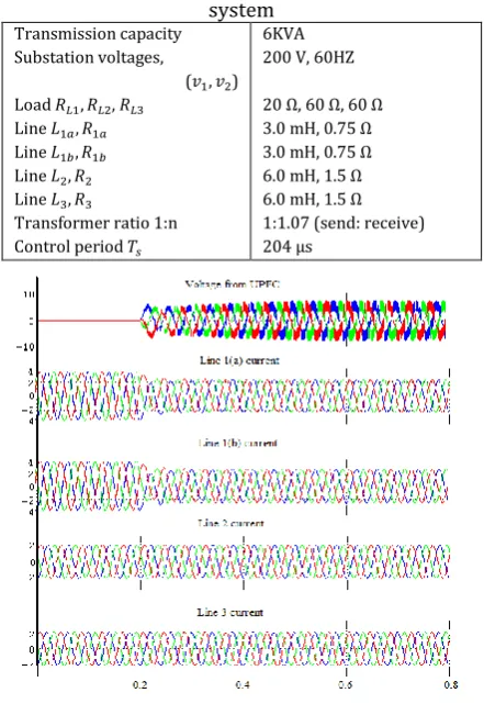
Table-2: Parameters of multiple loop same substation system
Transmission capacity Substation voltages,
( ) Load ,
Line Line Line Line
Transformer ratio 1:n Control period
6KVA 200 V, 60HZ
20 Ω, 60 Ω, 60 Ω 3.0 mH, 0.75 Ω 3.0 mH, 0.75 Ω 6.0 mH, 1.5 Ω 6.0 mH, 1.5 Ω 1:1.07 (send: receive) 204 µs
[image:4.595.327.548.419.740.2]© 2016, IRJET | Impact Factor value: 4.45 | ISO 9001:2008 Certified Journal | Page 886
Fig.9 shows the simulink waveforms of theoutput reference voltage of the UPFC serird converter, line 1.a, line 1.b currents and line 2 , line 3 currents. It is seen that UPFC is switched into line 1 after 0.2 milli seconds. So that output reference voltage will increase after the switching.
[image:5.595.58.259.263.415.2]Line 1.a and line1.b currents are decreased after switching the controller this is because of the controller inject the reactive power in to the line. So, the current drawn from the mains are reduced. There is no change in line 2 and line 3 currrent as there is no impact of UPFC on line 2 and line 3.
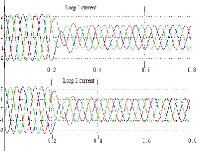
Fig-10: Loop current of multiple loop system
Fig .10 shows the loop 1 and loop 2 currents. Before installing the UPFC, the difference in reactance to inductance of lines causes the flow of circulating currrents. After switching the UPFC converter in to the line, loop currrents reduced from 2.2amps to 1.2 amps as shown above. Decrease in loop currents resuls in the decrease in the line losses, hence achieved the line loss minimization in the multiple loop same substation system.
Table-3: Comparision of THD values
Distrubution
systems With UPFC With out UPFC
Isolated loop 0.29% 11.6%
Multiple loop 0.32% 18.03%
From above table.3,clearly observe placing UPFC in isolated and multiple loop distribution systems total harmonic distortion(THD) value is almost reduced.
5. CONCLUSION
In this paper, proposed a methodology for line loss minimization in radial distribution system. Existing systems have been reconfigured to improve the system efficiency. It is pointed out that there are two types of
losses occurred they include line loss due to existence of load and secondly loop current existence due to reconfiguration. Line loss due to load current is inevitable. So, in this paper system is modelled to eliminate the loop currents. The radial system is examined by considering two types of loops say isolated and multiple loop systems. UPFC controller has been used to compensate the line loss. The system is tested by designing the system in mat lab. PI controller and fuzzy logic controllers have used to implement the system. The obtained results have been presented. It is concluded that using UPFC technology it is possible to minimize the objective function of line loss.
REFERENCES
[1] N. Okada, H. Kobayashi, K. Takigawa, M. Ichikawa, and K. Kurokawa “Loop power flow control and voltage characteristics of distribution system for distributed generation including PV system,” in Proc.
3rd WorldzzConf. Photovoltaics Energy Convers.,
2003, pp. 2284–2287.
[2] N. Okada, “Verification of control method for a loop distribution system using loop power flow controller,” in Proc. IEEE Power Syst. Conf.
Expo.,2006, pp. 2116–2123.
[3] W.-T. Huang and S.-T. Chen, “Line loss reduction by distribution system upgrading from radial to normally closed-loop arrangement,” in Proc. 9thInt.
Conf. Hybrid Intell. Syst., 2009, pp. 334–339.
[4] T.-H. Chen, W.-T. Huang, J.-C. Gu, G.-C. Pu, Y.-F. Hsu, and T.-Y. Guo,“Feasibility study of upgrading primary feeders from radial and open-loop to normally closed-loop arrangement,” IEEE Trans.
Power Syst., vol. 19, no. 3, pp. 1308–1316, Aug. 2004.
[5] R. Gupta, A. Ghosh, and A. Joshi, “Performance comparison of VSCbased shunt and series compensators used for load voltage control in distribution systems,” IEEE Trans. Power Del., vol. 26, no. 1, pp. 268–278, Jan. 2011.
[6] L. Gyugyi, “Unified power-flow control concept for flexible ac transmission systems,” IEE Proc. C
Generat., Transmiss. Distrib., vol. 139, pp. 323–331,
Jul. 1992.
[7] M. Sayed, N. Inayoshi, T. Takeshita, and F. Ueda, “Line loss minimization of loop distribution systems using UPFC,” IEEJ Trans. Ind. Appl., vol. 128- D, pp. 508–515, Apr. 2008.
© 2016, IRJET | Impact Factor value: 4.45 | ISO 9001:2008 Certified Journal | Page 887
distribution systems using UPFC,” IEEE Trans.PowerElectron., vol. 26, no. 6, pp. 1694–1703, Jun. 2011.
[9] H. Fujita, H. Akagi, and Y.Watanabe, “Dynamic control and performance of a unified power flow controller for stabilizing an ac transmission system,”
IEEE Trans. Power Electron., vol. 21, no. 4, pp. 1013–
1020, Jul. 2006.
[10]H. Abu-Rub, A. Iqbal, and J. Guzinski, High
Performance Control of AC Drives With
MATLAB/Simulink Models. New York, NY, USA:
Wiley-Interscience, 2012.
[11]Mahmoud A. Sayed, Takaharu Takeshita, “Line loss minimization in isolated substations and multiple loop distribution systems using the UPFC,” IEEE
Trans. Power Electron., vol. 29, no. 11, pp.5813-5822,