International Journal of Emerging Technology and Advanced Engineering
Website: www.ijetae.com (ISSN 2250-2459,ISO 9001:2008 Certified Journal, Volume 5, Issue 8, August 2015)
158
Design and Development of A Dual Channel Temperature
Acquisition System to Log Temperature Distribution in Base
Plates During Different Welding Operations.
Rahul Jain
1, Sheetal Bhagat
2, Tanushi Pandey
3, D.V. Gadre
4, Pradeep Khanna
5 1,2,3Student, Department of Manufacturing Process and Automation Engineering, NSIT, Delhi, India
4Associate Professor, Department of Electronics and Communication Engineering, NSIT, Delhi, India 5Assistant Professor, Department of Manufacturing Process and Automation Engineering, NSIT, Delhi, India Abstract— The research paper describes the design and
development of a dual channel temperature acquisition system to measure and log temperature distribution in base plates during different welding operations using k-type thermocouples. Instrumentation and signal conditioning circuit is developed to give the appropriate electrical signal (in the range of analog inputs) to the microcontroller. The instrument provides a flexible, novel and cost efficient alternative to the existing temperature measuring devices with comparable performance. The system can also be interfaced with MATLAB or a custom made GUI to log and plot temperature time graphs for all individual channels.
The system was calibrated and multiple experimentation was carried out within an accuracy of +-3°C. The observations were also validated using an infrared temperature sensor.
Keywords— Arduino, Cooling rates, Logging, Low-cost instrumentation, microcontroller, thermocouple, Welding temperature measurement.
I. INTRODUCTION
Temperature measurement in today‟s industrial environment encompasses a wide variety of needs and applications. To meet this wide array of needs the process control industry has developed a variety of temperature transducers and logging equipment to cater to this demand. However, these devices have complex circuitry and high cost. To cater to the demands of the industry, we attempted to design and develop a cost effective yet a comparable temperature measurement system using k-type thermocouples as temperature transducers and ATmega328P as the microcontroller.
The design comprises of a three-step process of temperature sensing, signal conditioning and logging and display.
II. DESIGN AND DEVELOPMENT
[image:1.612.330.569.269.354.2]This section describes the design and development of the temperature measuring system. Figure 1 given below depicts a schematic representation of the system.
Figure 1: Block Diagram of the temperature-measuring instrument
The voltage differential input generated by the thermocouple due to Seebeck effect is subjected to the required signal conditioning in the signal-conditioning unit (SCU) including conversion of the analog values to their digital equivalent. This output is then provided to the microcontroller display unit. The IC used in the microcontroller unit is the ATMega328P. The microcontroller communicates with the SCU through SPI (Serial Peripheral Interface) protocol and thereafter the temperature is displayed on the 16x2 LCD display.
III. DETAILED DESCRIPTION OF COMPONENTS
Following is a description of the important components used in the instrument.
A. Temperature Transducer: Type K Thermocouple
Use of thermocouples has certain advantages over the other thermal sensors: cost effectiveness, simple mechanism and faster response, wider range, no heat losses and no excitation requirements. Other advantages include flexibility of probes, easy availability and versatility. They produce only millivolts of output, so, they require precision amplification for signal conditioning [3].
International Journal of Emerging Technology and Advanced Engineering
Website: www.ijetae.com (ISSN 2250-2459,ISO 9001:2008 Certified Journal, Volume 5, Issue 8, August 2015)
159
It constitutes of chromel {90% nickel and 10% chromium} and alumel {95% nickel, 2% manganese, 2% aluminium and 1% silicon}), and is the most common general purpose thermocouple with a sensitivity of approximately 41 µV/°C (chromel positive relative to alumel when the junction temperature is higher than the reference temperature)[3]. It provides a temperature range of -200°C to +1350°C.
B. Signal conditioning unit with cold junction compensation
Signal conditioning means manipulating an analog signal in such a way that it meets the requirements of the next stage for further processing. It involves amplification, level shifting, filtering, impedance matching, modulation, demodulation, isolation, and other functions [4]
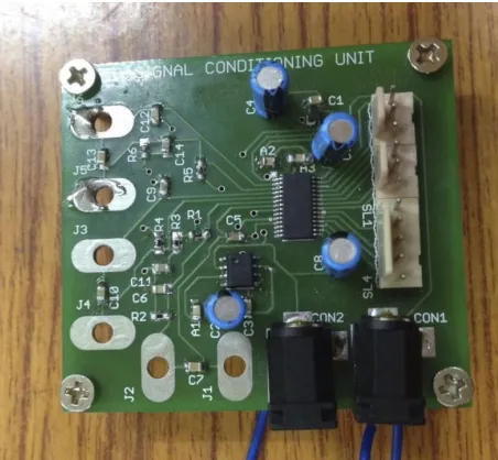
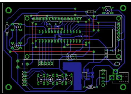
[image:2.612.334.554.133.340.2]The signal-conditioning unit is a PCB housing components for conditioning data from 2 channels. For this purpose, three Texas Instrument ICs are used, namely LMP90100 (AFE), LM4140 (Voltage Reference) and LM35D (Local temperature sensor for cold junction compensation). Figures 2,3 and 4 depict the schematic, board file and the fabricated signal-conditioning unit PCB.
[image:2.612.325.551.364.573.2]Figure 2. Schematic for Signal Conditiong board. (EAGLE CAD)
Figure 3. Board File for Signal Conditioning Unit (EAGLE CAD)
[image:2.612.53.287.405.546.2]International Journal of Emerging Technology and Advanced Engineering
Website: www.ijetae.com (ISSN 2250-2459,ISO 9001:2008 Certified Journal, Volume 5, Issue 8, August 2015)
160
C. Microcontroller unit and display
[image:3.612.331.558.127.295.2]The microcontroller IC in the unit board is ATMega328P, an 8-bit AVR RISC-based high performance microcontroller. The microcontroller communicates with the SCU through SPI (Serial Peripheral Interface) protocol for the readings to be displayed on a 16x2 LCD screen. Figures 5,6 and 7 depict the schematic, board file and the microcontroller board with display.
[image:3.612.51.283.242.433.2]Figure 5. Schematic of Microcontroller Unit
[image:3.612.332.559.318.507.2]Figure 6. Board File of Microcontroller unit and display
Figure 7. Fabricated microcontroller and display unit
Figure 8. Instrument displaying room temperature
IV. SELECTION OF COMPONENTS
The selection of components is a crucial step in the designing and fabrication process. Criteria like cost effectiveness, availability, reliability are the primary factors taken into account to enable the selection of a component.
A. LMP90100 (analog front end) [5]
[image:3.612.55.280.456.617.2]International Journal of Emerging Technology and Advanced Engineering
Website: www.ijetae.com (ISSN 2250-2459,ISO 9001:2008 Certified Journal, Volume 5, Issue 8, August 2015)
161
[image:4.612.368.512.180.273.2]The devices features a precision, 24-bit Sigma Delta Analog -to- Digital Converter (ADC) with a low- noise programmable gain amplifier and a fully differential high impedance analog input multiplexer. The background calibration feature essentially eliminates gain and offset errors across temperature and time, providing measurement accuracy without sacrificing speed and power consumption. Collectively, these features make the LMP90100 sensor applications such as temperature, pressure, strain gauge, and industrial process control.
Figure 9. LMP 90100 (Pin Diagram) [5]
B. LM4140 (voltage reference) [6]
[image:4.612.97.235.257.406.2]LM4140 is used to provide a voltage reference to the LMP90100. The LM4140 series of precision references are designed to combine high accuracy, low drift and noise with low power dissipation in a small package.
Figure 10. LM4140 Pin Diagram [6]
C. LM35D (temperature transducer for CJC) [7]
The LM35 series are precision integrated-circuit temperature devices with an output voltage linearly- proportional to the Centigrade temperature. The LM35 device does not require any external calibration or trimming to provide typical accuracies of ±¼°C at room temperature and ±¾°C over a full −55°C to 150°C temperature range.
[image:4.612.382.517.399.530.2]The low-output impedance, linear output, and precise inherent calibration of the LM35 device makes interfacing to readout or control circuitry especially easy
.
Figure 11. LM 35D Pin Diagram [7]
D. AtMega328P (microcontroller) [8]
AtMega328P is a 8 bit microcontroller by Atmel Corporation. It has 23 programmable I/O lines. The microcontroller communicates with the LMP90100 through SPI Protocol and displays the temperature on the LCD with a refresh rate of 1 second. The display gives a basic idea of the temperature at the hot junction. Detailed data is logged, which can be used to plot temperature time graphs.
Figure 12. AtMega328P Microcontroller pin diagram [8]
V. CALIBERATION
The equipment was calibrated with the help of three different temperature standards, namely, boiling water, ice point and boiling sulphur temperature measurement. The temperature displayed by the microcontroller display unit was compared with the temperature, as read by the infrared temperature sensor.
A. Temperature of boiling water
[image:4.612.75.257.484.612.2]International Journal of Emerging Technology and Advanced Engineering
Website: www.ijetae.com (ISSN 2250-2459,ISO 9001:2008 Certified Journal, Volume 5, Issue 8, August 2015)
162
B. Temperature of ice
The thermocouple was kept in contact with a block of water ice. The temperature displayed by the LCD in this case was 1°C.
C. Temperature of Sulphur
The thermocouple was put in burning sulphur and the temperature displayed was within the accuracy of +-3°C.
VI. CONCLUSIONS
A simple, cost effective and reliable temperature measurement instrument was designed, fabricated and calibrated successfully. The K-type thermocouple is used as a temperature sensor. A signal conditioning unit with cold junction compensation and a microcontroller unit with display has been developed. The working of the instrument is found satisfactory and in conformity with expected results.
REFERENCES
[1] Mitchell S. Cottrell, „Temperature Measurement‟, Mechanical Instrumentation Course ME 4840, Missouri University of Science and Technology
[2] “Design of Signal Conditioning Circuit for MEMS Based Sensor and it‟s Spice Modeling Kousik Dey”, Debanjan Ghosh Roy, Sagar Mukherjee, Kalyan Biswas
[3] “Temperature Sensors”, Walt Kester, James Bryant, Walt Jung [4] Jichun Zhang and Andrew Mason, “Characterization of a
Configurable Sensor Signal Conditioning Circuit for Multi-Sensor Microsystems”, IEEE sensors journal, vol. 4, pp 198-201,2004 [5] “LMP90100 and LMP9009x Sensor AFE System: Multichannel,
Low-Power, 24-Bit Sensor AFE With True Continuous Background Calibration”, Texas Instruments Datasheet
[6] “LM 4140 High Precision Low Noise Low Dropout Voltage Reference”, Texas Instruments Datasheet
[7] “LM35 Precision Centigrade Temperature Sensors”, Texas Instruments Datasheet

![Figure 11. LM 35D Pin Diagram [7]](https://thumb-us.123doks.com/thumbv2/123dok_us/8697501.878670/4.612.75.257.484.612/figure-lm-d-pin-diagram.webp)
