International Journal of Emerging Technology and Advanced Engineering
Website: www.ijetae.com (ISSN 2250-2459,ISO 9001:2008 Certified Journal, Volume 5, Issue 8, August 2015)
72
Computational Modeling Design and Fea Analysis on Wet
Multi Plate Clutch for Pulsar 150dts-I Motor Cycle
C. Kirankumar
1, Dr. C. Bhaskar Reddy
2, S. Jaya Kishore
31P.G Student,CAD/CAM , Sri Kalahasteeswara Institute of Technology, Srikalahasti, India 2HOD & Associate Professor, Sri Kalahasteeswara Institute of Technology, Srikalahasti, India 3Mechanical Engineering, Assistant Professor, Siddartha Institute of Science and Technology, Puttur, India
Abstract— In this present paper, we design Wet clutch by Computational Modelling and z-D drawing’s are designed for multiplate clutch from computational calculations.3D model model is creted in the CATIA modeling software for pulsar 150cc bike.we have dne FEM analysis by varying friction materials with some non metals and composite materials we are going to find out which material is best suited for the lining of friction surfaces.Structural Analysis is done by using ANSYS-WORKBENCH software.
Keywords— Ansys, CATIA, Copper, Cork, SF00, SF-BU, Wet-Clutch plate, Vonmises stress, Vonmises strain, Total Deformation.
I. INTRODUCTION
It is an instrument for transmitting pivot, which can be locked in and withdrew. Grasps are valuable in gadgets that have two turning shafts. In these gadgets, one pole is commonly determined by an engine or pulley, and the other shaft. drives another gadget. Give us a chance to take an occurrence where one pole is driven by an engine and alternate drives a drill toss. The grip associate the two poles so they can either be bolted together and twist at the same rate (drew in), or be decoupled and turn at diverse paces
A. Friction Clutches:
The contact friction clutch is an imperative part of any car machine. It is a connection in the middle of motor and transmission framework which directs power, in type of torque, from motor to the apparatus gathering At the point when vehicle is begun from halt grasp is locked in to exchange torque to the transmission; and when vehicle is in movement grip is initially separated of the drive to consider rigging determination and afterward again connected with easily to control the vehicle.
Fig.1.Engaged position of Wet-Clutch Plate
II. MATERIAL SELECTION FOR MULTI-PLATE CLUTCH
The materials utilized for the covering of grating surface of a grip called rubbing material f grinding coating materials, Qualities of the grating covering are as taking as follows:
1. It could have a high and uniform coefficient of grating under working conditions
2. It could not be influenced by dampness and oil
3. It have to be able to withstand high temperature brought about because of slipping
4. It could to have high imperviousness to wear impacts, for example, scoring, irking, and removal.
5. It could to have less push and strains.
6. It should to with stand load with less aggregate displacement.
International Journal of Emerging Technology and Advanced Engineering
Website: www.ijetae.com (ISSN 2250-2459,ISO 9001:2008 Certified Journal, Volume 5, Issue 8, August 2015)
[image:2.612.322.565.120.265.2]73 TABLE I
Material Properties
S.No Properties Young's Modulus (Mpa)
Poisson’s Ratio
Density (kg/m3)
1 Cork 32 0.25 180
2 Copper Powder Metal
135e3 0.35 8300
3 Sf001 7000 0.49 1350
4 Sf-Bu 7260 0.49 1250
III. MODELING OF WET CLUTCH
CATIA is software which is used for creation and modifications of the objects. In CATIA and design and modeling feature is available. Design means the process of creating a new object or modifying the existing one. Drafting means the representation or idea of the object. Modeling means converting 2D to 3D.
This is most progressive geometric demonstrating in three measurements. This regularly utilizes strong geometry shapes called picture to build the article.Another element of the CATIA framework is shading design capacity. By method for shading, it is conceivable to show more data on the representation screen hued pictures help to illuminate parts is a gathering or highlight measurements or host of different purposes.
By utilizing the basic capacities of the product as to the single information source standard, it gives a rich arrangement of apparatuses in the assembling environment as tooling plan and recreated CNC machining and yield.
Tooling choices spread forte instruments for
[image:2.612.43.298.140.296.2]embellishment, pass on throwing and dynamic tooling outline.
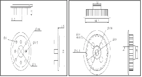
Fig.2.2-D representation of Base-Part and Double plate.
[image:2.612.324.569.292.418.2][image:2.612.325.564.443.556.2]
Fig.3.2-D representation of Friction-Plate and Assembly of Clutch.
[image:2.612.50.288.569.698.2]Fig.4.3-D representation of Friction-Plate of Wet Clutch Plate.
Fig.5.3-D representation of Exploded View of Wet Multi-plate Clutch.
IV. COMPUTATIONAL MODELLING
1.Power produced in Bike = 9000 rpm
2.Twisting Moment = 12.45 N-m @ 6500rpm
3.Co-efficent of friction in between the friction plates, µ = 0.3
4.Operating temperature in between plates°C = 150 – 250
5.Maximum pressureapplied N/mm2 = 0.4
6. r1and r2 outer and inner radius of friction faces
International Journal of Emerging Technology and Advanced Engineering
Website: www.ijetae.com (ISSN 2250-2459,ISO 9001:2008 Certified Journal, Volume 5, Issue 8, August 2015)
74
7. Average Uniform Pressure=0.0045867Mpa.
8. Generation of Heat Qg=2187.5 Joules
9.Area=11878.361mm2.
10.Heat flux per plate=7.3663*10-3W/mm2.
V. FINITE ELEMENT ANALYSIS
Finite Element Analysis was initially produced for utilization in the aviation and atomic commercial enterprises where the security of the structures is discriminating. Today, the development in use of the strategy is straightforwardly owing to the quick advances in PC innovation lately. Accordingly, business Finite Element bundles exist that are fit for tackling the most advanced issues, not simply in Structural Analysis. In any case, for an extensive variety of utilizations, for example, relentless state and transient temperature appropriations, liquid stream reproductions furthermore recreation ofassembling procedures, for example, Injection Molding and Metal framing. The finite element method is a powerful tool to obtain the numerical solution of wide range of engineering problems. The method is general enough to handle any complex shape or geometry, for any material under different boundary and loading conditions.
A. Advantages of FEM
The properties of each element are evaluated separately, so an obvious advantage is that we can incorporate different material properties for each element. Thus almost any degree of non-homogeneity can be included. There is no restriction on to the shape of medium; hence arbitrary and irregular shapes cause no difficulty like all numerical approximations FEM is based on the concept of description. Nevertheless as either the variations or residual approach, the technology recognizes the multidimensional continuous but also requires no separate interpolation process to extend the approximate solution to every point with the continuum.
B. Limitations of FEM
FEM reached high level of development as solution technology; however the method yields realistic results only if coefficient or material parameters that describe basic phenomena are available.
The most tedious aspects of use of FEM are basic process of sub-dividing the continuum of generating error free input data for computer.
C. Applications of FEM
Refering to temperature or heat flux distribution in the case of heat transfer problem.
Referring to Eigen value problems in solid mechanics or structural problem, natural frequencies, buckling loads and mode shapes are found, stability of laminar flows is found if it is a fluid mechanics problem and resonance characteristics are obtained if it is an electrical circuit problem, while for the propagation or transient problem, the response of the body under time varying force is found in the area of solid mechanics.
D. Structural Analysis
This analysis is used to perform to find Structural parameters such as Stresses, Strains,Deformation, Bending Moment and Shear stress. Structural analysis is probably the most common application of the finite element method as it implies bridges and buildings, naval, aeronautical, and mechanical structures such as ship hulls, aircraft bodies, and machine housings, as well as mechanical components such as pistons, machine parts, and tools.
Fig.6.Clutch plate is imported into ANSYS-WORKBENCH.
International Journal of Emerging Technology and Advanced Engineering
Website: www.ijetae.com (ISSN 2250-2459,ISO 9001:2008 Certified Journal, Volume 5, Issue 8, August 2015)
75 Fig.8.Boundary Condition’s applied to Clutch plate
Fig.9.Loads applied on Wet-Multi plate clutch.
Fig.10.Vonmises stress acting on Cork Clutch plate.
Fig.11.TotalDeformation acting on Cork Clutch plate.
Fig.12.Vonmises stress acting on Copper Clutch plate.
International Journal of Emerging Technology and Advanced Engineering
Website: www.ijetae.com (ISSN 2250-2459,ISO 9001:2008 Certified Journal, Volume 5, Issue 8, August 2015)
76 Fig.14.Totaldeformation acting on Copper Clutch plate.
Fig.15.Vonmises stress acting on SF001 Clutch plate.
Fig.16.Vonmisesstrain acting on SF001 Clutch plate.
Fig.17.Totaldeformation acting on SF001 Clutch plate.
Fig.18.Vonmises stress acting on SF-BU Clutch plate.
International Journal of Emerging Technology and Advanced Engineering
Website: www.ijetae.com (ISSN 2250-2459,ISO 9001:2008 Certified Journal, Volume 5, Issue 8, August 2015)
[image:6.612.54.285.134.280.2]77 Fig.20.Totaldeformation acting on SF-BU Clutch plate.
VI. RESULTS &DISCUSSIONS
TABLE III
Results Obtained From Structural Analysis
S.N o
Parame ters
Cast
Iron Carbon Steel
SF001 SF-BU
1 Von-Mises Stress
(Mpa)
83.588
6.9955 0.00064 0.0359
2 Vonmis es strain
82.955
6.993 0.00041 0.0231
3 Total Deform ation(m m)
82.314
6.990 0.00039 0.02246
E. Graphs
Fig21. Von-Mises Stress for Cast Iron Vs Carbon Steel Vs SF001 Vs SF-BU.
Fig22. Von-Mises Strain for Cast Iron Vs Carbon Steel Vs SF001 Vs SF-BU.
Fig23. Total Deformation for Cast Iron Vs Carbon Steel Vs SF001 Vs SF-BU.
VII. CONCLUSION
Computational configuration demonstrating and
[image:6.612.321.564.313.464.2]International Journal of Emerging Technology and Advanced Engineering
Website: www.ijetae.com (ISSN 2250-2459,ISO 9001:2008 Certified Journal, Volume 5, Issue 8, August 2015)
78 REFERENCES
[1] Karl Friedrich Benz has created the first business gas fueled vehicles, the acclaimed Tri-Cycle, he likewise was the first individual to concoct and utilize the grasp framework to the auto,1885
[2] Exedy and Daikin, Exedy Corp., it was accounted for that when Karl Benz has created the first business gas fueled vehicles, the acclaimed Tri-Cycle, he likewise was the first individual to concoct and utilize the grasp framework to the auto,1918.
[3] Gorin and Shilyaev concentrated on the explanatory arrangements between two pivoting annular plates having little holes. Since the diagnostic arrangements were gotten from the Navier-Stokes mathematical statements utilizing a basic methodology, 1976.
[4] Matveev and Pustovalov Designed a numerical reproduction for stream Between
annular circles by utilizing an unequivocal preservationist plan for the Navier- Stokes mathematical statements,1982.
[5] Zlatomir zivanovic, Miodrag Milic ―Thermal Loadof Multi-disc wet friction Assemblies at Braking Regime‖ Strojniski vestnik-Journal of Mechanical Engineering,2011.
[6] Oday I.Abdullah, Josef Schlattmann , ― Finite Element Analysis for Grooved Dry Friction Clutch‖ AMEA,Vol.2,No.1, ISSN 2167-6380.