International Journal of Emerging Technology and Advanced Engineering
Website: www.ijetae.com (ISSN 2250-2459,ISO 9001:2008 Certified Journal, Volume 4, Issue 8, August 2014)
94
Control of a Doubly-Fed Induction Generator for Wind Energy
Conversion Systems by RST Controller
Abdellah Boualouch
1, Abdellatif Frigui
2, Tamou Nasser
3, Ahmed Essadki
4, Ali Boukhriss
5 1-5Research Laboratory of Electronics Engineering LRGE, ENSET, University of Mohammed V, Souissi, Rabat, Morocco Abstract—This work deals with the vector control of the
active and reactive powers of a double-fed induction generator (DFIG) for wind energy conversion systems (WECS) by the polynomial RST controller. The control of the statoric power transfer between the machine and the grid is achieved by acting on the rotor parameters and control is provided by the polynomial RST controller. The performance and robustness of the controller are compared with PI controller and evaluated by simulation results in MATLAB/simulink.
Keywords—Vector control, DFIG, wind energy, RST.
I. INTRODUCTION
The demand for electrical energy has become important, this has resulted in the decreasing of the world stock of hydrocarbon. Faced with this problem and the challenges of global warming of the earth caused by gas emissions associated with excessive energy source fossil fuels consumption, it is necessary to use sources of new energy to be harmless to humans and the environment.
Among these energies there is wind power, which is to produce electrical energy from the kinetic energy of the wind, this type of energy has been the subject of much research in electrical engineering, in order to improve the electromechanical conversion and quality of energy supplied.
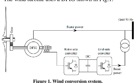
Currently the doubly fed-induction machine is the most used for high wind turbine power [1], it allows to operate in a wide range of wind speed, and get the maximum power for each wind speed [1],[4]. The stator of the machine is directly connected to the grid while the rotor is connected through a static converter to control the power passed to the grid. Due to the reduced rotor power the size of the rotor converter is reduced [1], add to this the ability to adjust the voltage at the connection points of this machine that is the reason for which we find the DFIG in high wind turbine power [4].
The use of this type of machine can adopt several types of control such as vector control, which is to make the DFIG similar to a DC generator with separate excitation.
It is in this context we have established indirect vector control to command the active and reactive power using a polynomial RST controller based on the theory pole placement. The goal of this work is to present the performance of this type of controller against the classic controller.
II. TURBINE MODEL
[image:1.612.329.561.324.465.2]The wind turbine uses a DFIG shown in Fig.1.
Figure 1. Wind conversion system.
The Mechanical turbine power Pmt and the torque Tt available on the shaft of the turbine is given by [2-3]:
3 1
² ,
2
mt p
P
R V C
(1)
3
t
t
1
R²V Cp λ, 2
T
(2)
Where λ is the tip speed ratio of the rotor blade tip speed to wind speed defined as: λ=(Ωt.R/v)and ρ represents the
density of the area, R is the radius of the wind turbine, Ωt is turbine speed, v the wind speed, β is the angle of pitch and Cp is the power coefficient of the wind turbine given by the following relation [6]:
116 21, 0.51 ( 0.4 5)e i 0.0068
p C
i
(3)
3 1
1 1 0.035 0.08 1
International Journal of Emerging Technology and Advanced Engineering
Website: www.ijetae.com (ISSN 2250-2459,ISO 9001:2008 Certified Journal, Volume 4, Issue 8, August 2014)
95
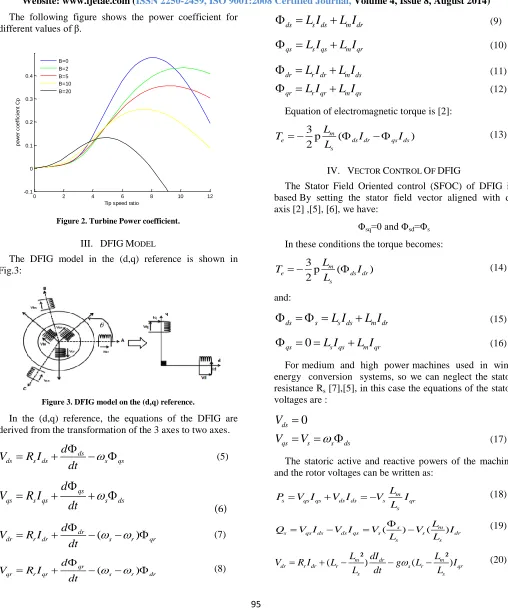
The following figure shows the power coefficient for different values of β.
0 2 4 6 8 10 12
-0.1 0 0.1 0.2 0.3 0.4
Tip speed ratio
p
o
w
e
r
c
o
e
ff
ic
ie
n
t
C
p
[image:2.612.50.558.124.738.2]B=0 B=2 B=5 B=10 B=20
Figure 2. Turbine Power coefficient.
III. DFIGMODEL
[image:2.612.64.266.176.332.2]The DFIG model in the (d,q) reference is shown in Fig.3:
Figure 3. DFIG model on the (d,q) reference.
In the (d,q) reference, the equations of the DFIG are derived from the transformation of the 3 axes to two axes.
ds
ds s ds s qs
d
V
R I
dt
(5)qs
qs s qs s ds
d
V
R I
dt
(6)
(
)
dr
dr r dr s r qr
d
V
R I
dt
(7)( )
qr
qr r qr s r dr
d V R I
dt
(8)
ds
L I
s dsL I
m dr
(9)qs
L I
s qsL I
m qr
(10)dr
L I
r drL I
m ds
(11)qr
L I
r qrL I
m qs
(12)Equation of electromagnetic torque is [2]:
3
p ( )
2
m
e ds dr qs ds
s L
T I I
L
(13)
IV. VECTOR CONTROL OF DFIG
The Stator Field Oriented control (SFOC) of DFIG is based By setting the stator field vector aligned with d-axis [2] ,[5], [6], we have:
Φsq=0 and Φsd=Φs
In these conditions the torque becomes:
3
p ( )
2
m
e ds dr
s L
T I
L
(14)
and:
ds s
L I
s dsL I
m dr
(15)0
qs
L I
s qsL I
m qr
(16)For medium and high power machines used in wind energy conversion systems, so we can neglect the stator resistance Rs [7],[5], in this case the equations of the stator voltages are :
0
ds
V
qs s s ds
V
V
(17)The statoric active and reactive powers of the machine and the rotor voltages can be written as:
m
s qs qs ds ds s qr
s L
P V I V I V I
L
(18)
( s) ( m) s qs ds ds qs s s dr
s s
L
Q V I V I V V I
L L
(19)
² ²
( m ) dr ( m )
dr r dr r s r qr
s s
L dI L
V R I L g L I
L dt L
[image:2.612.67.275.410.520.2]International Journal of Emerging Technology and Advanced Engineering
Website: www.ijetae.com (ISSN 2250-2459,ISO 9001:2008 Certified Journal, Volume 4, Issue 8, August 2014)
96
² ²
( m ) qr ( m ) ( m s)
qr r qr r s r dr
s s s
dI
L L L V
V R I L g L I g
L dt L L
(21)
In steady state, the second derivative terms in (20) and (21) are nil, the term L ²
( m )
r s
L L
constitutes cross-coupling
[image:3.612.54.280.224.420.2]terms can be neglected because of their small influence, Fig.4 shows the internal system of DFIG.
Figure 4. DFIG internal system.
Vdr and Vqr are the components to impose on the machine to get the desired rotor currents.
V. RSTCONTROLLER SYNTHESIS
RST controller is a polynomial controller based on the robust pole placement theory, he has the advantage of solving the tradeoff between rapidity and performance, compared with proportional integral PI controller.
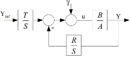
[image:3.612.60.274.603.697.2]The RST controller is composed of three polynomials R, S, and T. The determination of strategy of the three polynomial allows performance tuning of the servo with the synthesis parameters Tc (control horizon) and Tf (filtering horizon) [6] the block-diagram of a system with its RST controller is presented on fig.5 [4]:
Figure 5. Block diagram of the RST controller.
A and B are respectively the denominator and the numerator of the transfer function of the system, Yref is the reference and γ is the disturbance.
In our case:
²
( m )
s r s r
s L A L R pL L
L
And BL Vm s (22)
The transfer-function of the regulated system is:
ref
BT BS
Y Y
AS BR AS BR
(23)
To determine S(p) and R(p) we specified an arbitrary stability polynomial D(p), calculated according to the Bezout equation: D = AS + BR with:
deg( ) deg( ) deg(S)
D
A
For the proposed model, we have:
1 0
0
3 2
3 2 1 0
2
2 1 0
1 0
A a p a
B
b
D
d p
d p
d p d
S
s p
s p s
R
r p r
(24)
With the strategy of robust pole placement, the polynomial D is written as:
2
1
1
(
)(
)
c f
D
CF
s
s
T
T
(25)With:
C: Command polynomial F: Filter polynomial
Tc :Control horizon Tf: Filtering Horizon and:
1
c c P
T
: pole of polynomial C.
1
f f P
T
: double pole of the polynomial F.
International Journal of Emerging Technology and Advanced Engineering
Website: www.ijetae.com (ISSN 2250-2459,ISO 9001:2008 Certified Journal, Volume 4, Issue 8, August 2014)
97
5 5
²
( )
s r c A
m s r
s L R
p p
L
L L
L
(26)
To make the control less sensitive to noise and therefore make the most robust control setting Tc> 3Tf
²
( )
1
3 5
m s r
s f
s r L L L
L T
L R
(27)
From 25, 26 and 27, we deduce the coefficients of polynomial D which are linked to the coefficients of S and R by the Sylvester matrix [4]. Thus, we can determine the parameters of the RST controller as follows:
3 2
1
3 1 2
1 1
2 1 1
1
1 0 1 0 1
1 0 1
1
0 0 0
0 0
0 0
0
d
s
a
d
a s
a
s
d
a s
s
d
a s
b r
d
a s
r
d
b r
b
T
r
d
r
b
(28)
VI. SIMULATIONS AND RESULTS
To analyze the RST controller performance, simulations are performed by MATLAB/Simulink, the parameters of the DFIG studied are given in the Annex.
A. Reference tracking
The machine speed is attached to 1450rpm in ideal conditions, the active power reference Pref is 0.7MW and 1.5MW. The reactive power reference Qref is 0.5MVAR, 1MVAR and 0.25MVAR.Fig.6 shows the response of active and reactive power by the PI and RST controller.
0 0.5 1 1.5 2 2.5 3 3.5 4 4.5 5 0
0.5 1 1.5 2
Temps(s)
p
u
is
s
a
n
c
e
a
c
ti
v
e
(
M
W
)
Pref Ps(PI) Ps(RST)
0 0.5 1 1.5 2 2.5 3 3.5 4 4.5 5 -1.5
-1 -0.5 0 0.5
Temps(s)
p
u
is
s
a
n
c
e
r
é
a
c
ti
v
e
(
M
V
A
R
)
[image:4.612.51.241.310.447.2]Qref Qs(PI) Qs(RST)
Figure 6. Response to the active and reactive power using PI and RST controller (Reference tracking).
From the figure, we can conclude that the stator active and reactive power Ps and Qs follow the reference grandeur Pref and Qref. We note a quicker response for the RST controller and an exceeded for PI controller. The negative sign of the reactive power shows that the generator functions in capacitive mode, for inductive mode the power becomes automatically positive. In the end, the decoupling between the two axis is perfectly respected.
B. Robustness test
International Journal of Emerging Technology and Advanced Engineering
Website: www.ijetae.com (ISSN 2250-2459,ISO 9001:2008 Certified Journal, Volume 4, Issue 8, August 2014)
98
0 0.5 1 1.5 2 2.5 3 3.5 4 4.5 5 0 0.5 1 1.5 2 Time(s) a c ti v e p o w e r( M W ) Pref Ps(PI) Ps(RST)
[image:5.612.67.263.146.302.2]0 0.5 1 1.5 2 2.5 3 3.5 4 4.5 5 -1.5 -1 -0.5 0 0.5 Time(s) re a c ti v e p o w e r( M V A R ) Qref Qs(PI) Qs(RST)
Figure 7. Active and reactive power with Rr variation (2Rr).
0 0.5 1 1.5 2 2.5 3 3.5 4 4.5 5 0 0.5 1 1.5 2 Time(s) a c ti v e p o w e r( M W ) Pref Ps(PI) Ps(RST)
[image:5.612.340.537.147.303.2]0 0.5 1 1.5 2 2.5 3 3.5 4 4.5 5 -1.5 -1 -0.5 0 0.5 Time(s) re a c ti v e p o w e r( M V A R ) Qref Qs(PI) Qs(RST)
Figure 8. Active and reactive power with Ls variation (10%).
0 0.5 1 1.5 2 2.5 3 3.5 4 4.5 5 0 0.5 1 1.5 2 Time(s) a c ti v e p o w e r( M W ) Pref Ps(PI) Ps(RST)
0 0.5 1 1.5 2 2.5 3 3.5 4 4.5 5 -1.5 -1 -0.5 0 0.5 Time(s) re a c ti v e p o w e r( M V A R ) Qref Qs(PI) Qs(RST)
Figure 9. Active and reactive power with Lr variation (10%).
0 0.5 1 1.5 2 2.5 3 3.5 4 4.5 5 0 0.5 1 1.5 2 Time(s) a c ti v e p o w e r( M W ) Pref Ps(PI) Ps(RST)
[image:5.612.66.263.341.497.2]0 0.5 1 1.5 2 2.5 3 3.5 4 4.5 5 -1.5 -1 -0.5 0 0.5 Time(s) re a c ti v e p o w e r( M V A R ) Qref Qs(PI) Qs(RST)
Figure 10. Active and reactive power with Lm variation (5%).
From simulation results, we found that the RST controller is more robust, the response time is almost the same despite changes in the parameters of the DFIG.
VII. CONCLUSION
The work presented in this paper devoted to power control of DFIG used in wind turbine by the RST controller, after modeling the DFIG in the d and q axis, we have established a vector control of DFIG based in stator flux oriented, then the RST controller are synthesized and compared to a conventional PI controller.
We have presented the performance of the controller RST compared to a conventional PI controller, the robustness of the controller is evaluated and what allows us to have a decoupling between active and reactive power and thus independent control.
[image:5.612.66.263.537.692.2]International Journal of Emerging Technology and Advanced Engineering
Website: www.ijetae.com (ISSN 2250-2459,ISO 9001:2008 Certified Journal, Volume 4, Issue 8, August 2014)
99
VIII. APPENDIX
TABLEI DFIGPARAMETERS
Symbol Quantity Value
P Rated power 1.5MW
Vs Statoric voltage 690V – 50Hz
Vr Rotoric voltage 389V-14Hz
Rs Statoric resistance 0.012Ω
Rr Rotoric resistance 0.021 Ω
Ls Statoric inductance 0.0137 H
Lr Rotoric inductance 0.0136H
Lm Mutual inductance 0.0135H
G Slip 0.03
P Pole pairs 2
F The friction Coefficient 0.024N.m.s-1 J The moment of inertia 1000 kg.m2
TABLEII TURBINE PARAMETERS
Symbol Quantity Value
R Radius of the wind 35.25 m G Gain multiplier 0.48 ρ Air density 1.225kg/m3
REFERENCES
[1] A. Meroufel, Y.Djeriri, A. Massoum,and A.Hammoumi,―Commande vectorielle par les réseaux de neurones artificiels de l’énergie d’une MADA intégrée à un système éolien‖,Revue des Energies Renouvelables, vol.13, 2010, pp. 669–682.
[2] L. Xu, W. Cheng, ―Torque and reactive power control of a doubly-fed induction machine by position sensorless scheme‖, IEEE Transactions on Industry Applications, vol. 31, n°3, pp. 636-642, May/June 1995.
[3] A. Boukhriss, T. Nasser, A. Essadki, ―A Linear Active Disturbance Rejection Control applied for DFIG based Wind Energy Conversion System‖,International Journal of Computer Science Issues, Vol. 10, Issue 2, No 2, March 2013.
[4] F. Poitiers, M. Machmoum, R. Le Doeuff, M.E. Zaim, ―Control of a doubly-fed induction generator for wind energy conversion systems‖,International Journal of Renewable Energy Engineering, Vol. 3, N° 3, December 2001, pp. 373–378.
[5] A. Tapia, G. Tapia, J.X. Ostolaza and J.R. Saenz, ―Modeling and Control of a Wind Turbine Driven Doubly Fed Induction Generator‖, IEEE Transactions on Energy Conversion, vol. 18, n°2, pp. 194–204, June 2003.
[6] A.Belabbes, B.Hamane, M. Bouhamida, and A.Draou, ―Power Control of a Wind Energy Conversion System based on a Doubly Fed Induction Generator using RST and Sliding Mode Controllers‖,International Conference on Renewable Energies and Power Quality, Santiago de Compostela-Spain, March, 2012 [7] L. Zhang, C. Watthansarn and W. Shehered, ―A matrix converter