International Journal of Emerging Technology and Advanced Engineering
Website: www.ijetae.com (ISSN 2250-2459,ISO 9001:2008 Certified Journal, Volume 5, Issue 7, July 2015)
74
Performance Improvement of Microstrip Antenna Using EBG
Structure
Sanjiwani S. Patil
1, Prof. V. V. Joshi
21
M.E. Second Year, 2Assistant Professor, Department of Electronics & Telecommunication
Abstract—This paper represents the design of Electromagnetic Band gap (EBG) structure having fractal shape and its effect on antenna performance. The EBG structure is designed on substrate with dielectric constant 4.4 and thickness 1.6 mm. The proposed design is simulated using the high frequency structure simulator (HFSS). In our method, to overcome several limitations of patch antennas such as constrict bandwidth, low gain, excitation of surface waves, the EBG concept is applied. The aim of this paper is to design, simulate and fabricate the new EBG structure operating at 2.4GHz frequency and to study the performance of the rectangular microstrip antenna in terms of the bandwidth and VSWR with and without EBG structure which are characterized in terms of return loss and radiation pattern [1].
Keywords—Microstrip, Electromagnetic Band Gap (EBG), Bandwidth, Surface wave attenuation.
I. INTRODUCTION
In recent years, mobile communication has been grown tremendously, and new wireless technologies have rapidly emerged. Some of them are using multiple patch elements [2], changing the physical size of the antenna [3], modifying the radiator shape to allow current paths to travel at longer distances, and adding additional parts such as multi layers [4] or gaps (which again makes the antenna larger and of a higher profile). However, these antennas are large in sizes and can't be fitted into small and slim devices.
Microstrip patch antennas have been a best choice in mobile and radio wireless communication. This is because they have advantages such as low profile, low cost, conformal, and robust. However, they have disadvantages of low efficiency, narrow bandwidth and surface wave losses.
Recently, there has been considerable research effort in the electromagnetic band gap (EBG) structure for antenna application to suppress the surface wave [5] and improve the radiation performance of the antenna.
In this paper, the rectangular microstrip patch antenna has a new fractal electromagnetic band-gap (EBG) structure.
The patch antenna is fed by a driven terminal and is integrated within a fractal electromagnetic band-gap structure, on same substrate to raise the antenna gain and bandwidth. The fractal electromagnetic band-gap structure applied is a periodic structure with similar periods.
The outcome suggested that the surface waves which spread along the surface of the substrate can be inhibited by the multiple photonic band-gap structure because of its consequences of forbidden band, that it can diversify almost of electromagnetic waves energy in the substrate importantly, and that it has lower return loss (S11) compared to the conventional patch antennas and enhanced gain.
II. ELECTROMAGNETIC BAND GAP STRUCTURE
Surface wave are excited on microstrip antenna when the substrate єr > 1. Besides end fire radiation, surface wave
give rise to coupling between various elements of an array. Surface wave are launched into the substrate.
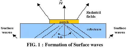
FIG. 1:Formation of Surface waves
These waves are incident on the ground plane at some angle shown in FIG 1, get reflected, then meet the dielectric-air interface, which also reflect them. Following the zig-zag path, they finally reach the boundaries of the microstrip structure where they are reflected back and diffracted by the edges giving rise to end-fire radiation.
[image:1.612.337.548.456.535.2]International Journal of Emerging Technology and Advanced Engineering
Website: www.ijetae.com (ISSN 2250-2459,ISO 9001:2008 Certified Journal, Volume 5, Issue 7, July 2015)
[image:2.612.64.279.149.368.2]75
FIG.2 : EBG Fundamental Structure
EBG structures are periodical cells composed of metallic or dielectric elements. Unique feature of EBG structures is to create the forbidden band of frequencies in which surface waves cannot propagate. Surface wave propagation is a serious problem in microstrip antennas. Surface waves reduce antenna efficiency and gain, limit bandwidth, increase end fire radiation, increase cross-polarization levels, and limit the applicable frequency range of microstrip antennas [5]. When the antenna operates in the frequency band of this prohibition, it will features, such as increasing the antenna return loss and bandwidth, the back, gain etc.
An antenna that is placed on a high-permittivity dielectric substrate may couple power into substrate modes. As substrate modes do not contribute to the primary radiation pattern, these modes are a loss mechanism. EBG structure can offer a real solution to this problem.
III. ANALYSIS &DESIGN
In this process, a rectangular microstrip patch antenna and its fractal EBG structure are designed by applying a Finite Element method (HFSS-Ansoft).
In Subsection A, the patch antenna is designed to function at an arbitrary chosen frequency. Then, in Subsection B, the EBG structure is designed to suppress the surface waves so as to enhance the gain of the patch antenna at its functioning frequency.
[image:2.612.349.543.247.406.2]A. Microstrip Antenna Design
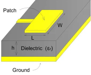
FIG.3 : Microstrip Patch Antenna
The Microstrip antenna is designed to operate at frequency 2.4GHz. For this design, the FR4 dielectric material (εr = 4.4) with dielectric loss tangent (tanδ) of
0.019 and height of substrate (h) 1.6mm are used. The dimensions are calculated using these parameters. It has L= 28.8 mm and W=37.7 mm. The microstrip antenna is exited by a microstrip line. [6]
The feed line is placed 7 mm from the centre of the patch. The feed location is selected to offer better impedance matching. The sizing of the substrate is 80 mm × 75 mm.
B. Microstrip Patch Antenna Surrounded by Fractal EBG
Structure
International Journal of Emerging Technology and Advanced Engineering
Website: www.ijetae.com (ISSN 2250-2459,ISO 9001:2008 Certified Journal, Volume 5, Issue 7, July 2015)
76
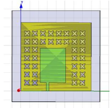
FIG. 4. Patch incorporated with the Fractal EBG Structure
The patch antenna is placed in the same plane as the EBG structure. It is placed at the centre of the EBG lattice. The patch antenna is fed with a microstrip feed at distance, dx=7 mm, from the edge as in the conventional patch antenna.
IV. SIMULATION &RESULTS
[image:3.612.70.268.135.310.2]Conventional microstrip antenna with PEC ground plane and FR4 substrate has been simulated. See FIG.5 To investigate the performance of the antenna, the High Frequency Structure Simulator (HFSS11) software is used for simulation study.
FIG.5. : The Simulation of Microstrip Antenna
With the stop band at 2.57GHz, return loss and Bandwidth of conventional rectangular micro strip patch antenna as shown in FIG 6 are -11.392dB & 2.57GHz-2.59GHz respectively.
1.00 1.50 2.00 2.50 3.00
Freq [GHz] -12.00
-10.00 -8.00 -6.00 -4.00 -2.00 0.00
d
B(S(L
u
mp
Po
rt
1
,L
u
mp
Po
rt
1
))
Ansoft Corporation XY Plot 1 HFSSDesign1
m1
m2 Curve Info dB(S(LumpPort1,LumpPort1)) Setup1 : Sw eep1
Name X Y
m1 1.8141 -6.7619 m2 2.5779 -11.3929
FIG. 6: The Simulated Return loss for Microstrip antenna
[image:3.612.351.533.396.573.2]To enhance the characteristics of conventional micro strip antenna, it is surrounding by dual layer of EBG structure and simulated as shown in FIG.7 .
FIG.7. The Simulation of Microstrip Antenna with EBG Structure
[image:3.612.54.282.468.661.2]International Journal of Emerging Technology and Advanced Engineering
Website: www.ijetae.com (ISSN 2250-2459,ISO 9001:2008 Certified Journal, Volume 5, Issue 7, July 2015)
[image:4.612.50.300.116.284.2]77
FIG 8: The Simulated Return loss for Microstrip antenna with EBG structure
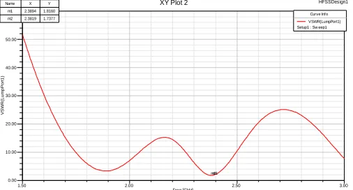
FIG. 9 shows the VSWR for proposed work. It is of value 1.81 which is less than 2. Thus the performance get improved.
1.50 2.00 2.50 3.00
Freq [GHz] 0.00
10.00 20.00 30.00 40.00 50.00 60.00
VSW
R
(L
u
mp
Po
rt
1
)
Ansoft Corporation XY Plot 2 HFSSDesign1
m1 m2
Curve Info VSWR(LumpPort1) Setup1 : Sw eep1 Name X Y
[image:4.612.50.303.350.486.2]m1 2.3894 1.8160 m2 2.3819 1.7377
FIG . 9: VSWR for microstrip antenna with EBG
V. FABRICATION AND MEASUREMENT
Thefabrication process involves 5 steps.
1. Generate mask on transparency
2. Photo exposure process 3. Etching in developer solution 4. Etching in Ferric Chloride
5. Soldering the probe for SMA connector
A SMA adapter was connected at one end of the microstrip line for measurement. Network analyzer will be used to measure the S11 of the antenna. The simulated and measured results of the prototype will be compared.
VI. HARDWARE &SOFTWARE USED
High Frequency Structure Simulator(HFSS 11):
It is used to simulate the proposed antenna. The reason for choosing HFSS is that it uses FEM methods, which deals with very complex structures and it predicts accurate results. It is a high-performance full-wave electromagnetic field simulator for 3D volumetric passive device modeling. It integrates simulation, visualization, solid modeling, and automation in an environment that facilitates learning and where solutions to 3D electromagnetic (EM) problems are quickly and precisely attained.
Vector Network Analyzer:
It is used for measurement of reflection coefficient. In the Vector Network Analyzer (VNA), the data is normally presented in the form of S-parameters and they are defined by measuring the voltage travelling waves between the ports.
VII. APPLICATIONS
The Proposed antenna can be used in following applications.
Antenna Applications:
Suppressing the surface waves in various antenna designs.
Design low profile wire antennas with good radiation efficiency.
Designing antennas with a high gain.
Bluetooth and Ultra wideband (UWB)
Wireless Communications
Microwave Circuit Designs:
Rejects the higher harmonics in the circuits
VIII. CONCLUSION
The fractal EBG structure has been proposed. A comparative study of simple rectangular microstrip antenna without and with EBG had been demonstrated. The bandwidth, gain of the antenna get improved. This antenna can be used in many applications.
International Journal of Emerging Technology and Advanced Engineering
Website: www.ijetae.com (ISSN 2250-2459,ISO 9001:2008 Certified Journal, Volume 5, Issue 7, July 2015)
78 REFERENCES
[1] Zheng Guo, Huiping Tian, Xudong Wang, Qun Luo, and Yuefeng Ji, "Bandwidth Enhancement of Monopole UWB Antenna With New Slots and EBG Structures" IEEE ANTENNAS AND WIRELESS PROPAGATION LETTERS, VOL 12 2013
[2] Hattan F. Abutarboush, R. Nilavalan, Senior S. W. Cheung, Karim M. Nasr, Thomas Peter, Djuradj Budimir, and Hamed Al-Raweshidy “A Reconfigurable Wideband and Multiband Antenna Using Dual-Patch Elements for Compact Wireless Devices” IEEE TRANSACTIONS ON ANTENNAS AND PROPAGATION, VOL. 60, NO. 1, JANUARY 2012
[3] Sanjeev Kumar Mishra, Rajiv Kumar Gupta, Avinash Vaidya, and Jayanta Mukherjee, “A Compact Dual-Band Fork-Shaped Monopole Antenna for Bluetooth and UWB Applications” IEEE ANTENNAS AND WIRELESS PROPAGATION LETTERS, VOL. 10, 2011 [4] Adam Narbudowicz, Xiu Long Bao, and Max J. Ammann,
"Dual-band Omnidirectional Circularly Polarized Antenna" IEEE ANTENNAS AND WIRELESS PROPAGATION LETTERS, 2011
[5] F. Yang, Y. Rahmat-Samii, “Microstrip Antennas integrated with electromagnetic band-gap structure: a low mutual coupling design for array application,” IEEE Trans. Antennas and Propagation, Vol. 51, Oct. 2003.
[6] C. A. Balanis, Antenna Theory, 2nd ed. New York: Wiley, 1997. [7] Fan Yang, Yahya Rahmat-Samii, Electromagnetic Band Gap
Structures in Antenna Engineering, Cambridge University Press 2009
[8] Hong-min Lee and Joong-kwan Kim, "Front-to-Back Ratio Improvement of a Microstrip Patch Antenna using an Isolated Soft Surface Structure", Proceedings of the 39th European Microwave Conference