Full Length Research Article
COMPARATIVE STUDY BY DIGITAL MECHANICAL SIMULATION OF THE BEHAVIOR OF
TILES IN MICRO - CONCRETE, SMALL AND WIDE SIZE
1
Bozabe R. Karka,
1Ahouannou Clément,
1Toukourou C. Akanho and
2Hounkonnou Mahouton Norbert
1Polytechnic School of Abomey-Calavi, University of Abomey-Calavi, Laboratory of Energetic and Mechanic Applied (LEMA), Cotonou / Benin, Box 01-2009
2International Chair of Mathematical Physics and Applications (ICMPA - UNESCO), University of Abomey-Calavi (BENIN)
ARTICLE INFO ABSTRACT
The present work has for object the comparison by digital simulation of the mechanical behavior of tiles in micro-concrete, the small and wide size to operate a choice on the dimensions and the existing geometrical forms. A modeling of tiles by the software of calculation of structures Robot Millennium 17.0 allowed on one hand to determine the variations of the fields of constraints and the fields of movements of these tiles, to compare the variations of the fields of constraints and movements of the various types of tiles, on the other hand. At the conclusion of this modeling, an objective analysis allowed to notice from the point of view mechanical resistance that Flat tiles, small size are advised with regard to the wide sizes whereas the Flemish tiles, the wide size are indicated well with regard to the small sizes.
© Copyright, IJDR, 2012, Academic Journals. All rights reserved.
INTRODUCTION
There are three types of tiles whom we can make with some micro-concrete: the Flemish tiles, the Romanic tiles and the Flat tiles (GRAM and GUT, 1991; ODUL, 1996). These tiles can be various dimensions grouped together in two big categories: tiles, wide size and tiles, small size. Certainly the advantages of a tile in micro-concrete are many (BRYS, 1990; YAMBA and al., 1997) but the mechanical resistance of tiles in the loads of maintenance is by far the most worrisome problem. With regard to the various efforts to which they will be submitted, we ask ourselves very often the question to know what type and dimensions of tile is it necessary so that she can better resist chargeable to maintenance for example?. That is why it turns out necessary to make a study either by using an adequate device, or by a simulation to guarantee a better choice. This study concerns the simulation. By using the method of fold resistance three points (BAGAN, 2002), we have to model in the software of calculation of structures Robot Millennium 17. 0, Flat and Flemish tiles of small and wide sizes. Then, after analysis by the method of the finished elements (GALLAGHER and al., 1976; GOURI and al., 1984) previously modeled tiles, we have finally, after interpretation and discussion of the results of the analysis makes recommendations to help the users to operate a better choice of tiles to cover their works.
MATERIAL AND METHODS
Methods
Configuration of flexion three points
For the present analysis, we hold the configuration of flexion three points type1 (Fig. 1), the most binding of three types of configuration of flexion three points which exist (BAGAN, 2001). It is about the configuration among which boards-supports and boards-loads are flat.
F: Load applied to the center;
B: width of the test tube;
H: height of the test tube
*Corresponding author: Bozabe R. Karka
Polytechnic School of Abomey-Calavi, University of Abomey-Calavi, Laboratory of Energetic and Mechanic Applied (LEMA), Cotonou / Benin, Box 01-2009
ISSN:
2230-9926
International Journal of Development ResearchVol. 3, Issue, 06, pp.005-016, June,2013
International Journal of
DEVELOPMENT RESEARCH
Article History:
Received 22nd
March, 2012 Received in revised form 11th April, 2013 Accepted 23rd
May, 2013 Published online 11th June, 2013
Key words:
Le: length of the test tube and L: distance between supports,
[image:2.612.168.440.85.267.2]L = 7/10 x Le
Figure 1: general configuration of the flexion three (3) typical points 1.
Digital Modeling of tiles
Geometrical characteristics of tiles and conditions in the limits
With the software of calculation of structures Robot Millennium 17.0, we model four tiles among which the geometrical characteristics and the conditions in the limits are recorded in the following picture:
Characteristics of the material micro-concrete
The material used for the manufacturing of tiles is some micro-concrete the characteristics of resistance and elasticity of which are (BAILON and al., 2000):
Compression Resistance RC = 20 Mpa
Module of elasticity of Young E = 30 000 Mpa Module of cutting G = 12 900 Mpa POISSON’s ratio = 0,2
Specific Weight Υ=24,530 KN/m3 Thermal Expansion 0,000010 (1/°C) Coefficient of amortization 0,04
Meshing of tiles in triangular finished elements
Because the thickness H of the tile following the axis Z is relatively small in front of the dimensions of the tile following the plan XY, the tiles which we use are qualified as "thin" plate. We know from now on that a thin plate appears all the more "flexible hose" as it is big dimensions with regard to its thickness. When she is "bent" under appropriate requests, her average plan becomes a surface averages curve. According to the requests which we apply to this plate, we can have following both modes of behavior (SUP AERO and IMBERT, 1979; CRAVEUR, 2001):
The behavior of membrane or state plan of constraints;
The behavior in flexion or are generated the movements outside the plan XY that is perpendicular in the average plan of the plate.
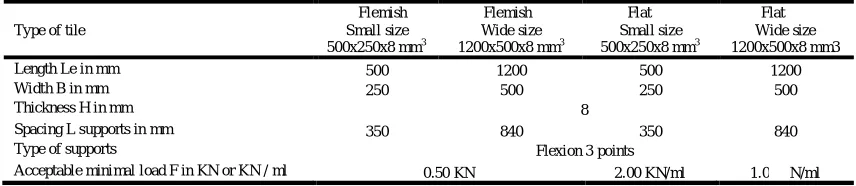
Table 1: geometrical characteristics of tiles and limit conditions
Type of tile
Flemish Small size 500x250x8 mm3
Flemish Wide size 1200x500x8 mm3
Flat Small size 500x250x8 mm3
Flat Wide size 1200x500x8 mm3
Length Le in mm 500 1200 500 1200
Width B in mm 250 500 250 500
Thickness H in mm 8
Spacing L supports in mm 350 840 350 840
Type of supports Flexion 3 points
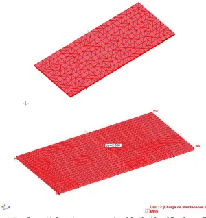
[image:2.612.91.519.351.444.2]Generally, the real requests on the structures stick are such as these two modes of behavior "coexist". Where from the necessity of grouping together in the same element the properties of "membrane" and those of "flexion" giving an element sticks said "complete".
According to the code of calculation of the software Robot millennium 17.0, the structures of types plate and hull like tiles are discreteness in finished elements surfaciques triangles (3 or 6 knots) and quadrangles (4 or 8 knots): it is the meshing. The model of calculation by finished elements uses these finished elements surfaciques with an estimate of the field of movement by the functions of shape of the first order u (x, y) and v (x, y) (relation 1-a and 1-b) for the behavior of membrane and for the characteristic behavior of the flexion, the field of cross-functional approximate movement w (x, y) thin patches is under the polynomial shape (1-e relation). Indeed, for a state plan of the constraints, the constraints and the deformations are the same in any perpendicular plan (XY) in the direction Z, we content ourselves then with a flat representation (plan XY) and the prismatic and volume elements will appear under the shape of triangles or quadrangles collectively called also elements of "membrane".
The reserved method of meshing is the one of COONS for Flat tiles as for Flemish tiles (ROBOT MILLENNIUM 17.0). The meshing by finished elements will be generated for a quadrangular paving stone. The following options of meshing were selected:
Generation of the meshing: user, division 1 = 24, division 2 = 10; Type of division: squared,
Finished Elements: triangles (3 knots), For the refinement of the meshing by finished elements, the following options were selected:
Type of refinement: double; Refinement: for all the elements.
X
Y Z
llb lll
llb lll
llb lll
llb lll
llb lll
llb lll
Fz=-0.160
Fz=-0.160
Fz=-0.060
Fz=-0.060
kN
Study of the behavior of tiles after load
Element sticks said "membrane"
Definition of the triangular finished element
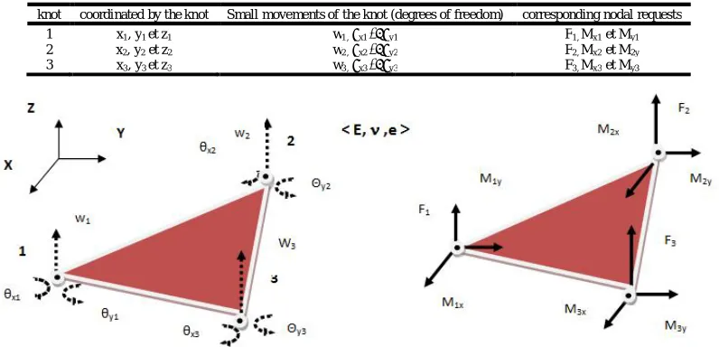
[image:4.612.154.454.56.374.2]The structural element used for this study is the triangular finished element represented on the Fig.3 below. This last one is indeed a triangle in three (3) knots placed in the various summits. Every tile is considered as an assembly of elements of triangular structures connected between them by functions of shape linear (interpolation) defined in the sub-paragraph b) Expression of the function of movement, below (1-a and 1-b). In the local mark (XYZ) or (XY) is the plan of the element, we place knots in three noted summits (1, 2, 3). The movements are noted in the Table 2 below, as well as the corresponding requests:
Table 2: the nodal efforts corresponding to the degrees of freedom
Knot Coordinated by the knot movements of the knot and deformed engendered corresponding nodal Requests
1 x1, y1 U1 ET V1 X1 et Y1
2 x2, y2 U2 ET V2 X2 et Y2
3 x3, y3 U3 ET V3 X3 et Y3
e: thickness of the following element Z Figure 3: triangular Element in flat constraints
[image:4.612.109.502.525.712.2]Expression of the function movement
We have to define for every element a field of approached movement which respects at least the continuity of the material when we pass of an element deformed in the other one. It is necessary for it that there is continuity of the movements along a border common to two elements. The simplest corresponding approximate field is linear (COATES and al., 1987; GAY and GAMBELIN, 1999). He spells:
U (x, y) = a0 + a1 x + a2y (1-a)
V (x, y) = b0 + b1 x + b2y (1-b)
Indeed we verify in that case that sides remain rectilinear after deformation. We determine the coefficients aj and bj (j = 0, 1, 2) by
writing that U and V coincide with the movements Ui and Vi in every knot i, what brings to six relations:
Ui = a0 + a1xi + a2yi i = 1,2,3
Vi = b0 + b1xi + b2yi i = 1,2,3
The coefficients aj and bj appear then as linear functions of the movements Ui and Vi. We substitute them in the relation (have 1-a
and 1-b) above, and the field of movement U (x, y) and V (x, y) takes the following matrix shape, where appears the matrix of interpolation [N (x, y)]:
= [ ( , )] .
⎩ ⎪ ⎨ ⎪
⎧ 11
2 2 3 3⎭ ⎪ ⎬ ⎪ ⎫ (1-c) With:
[N(x,y)] = x
Where we noted S: area of the element.
αi = xj yk – xk yj ; βi = yj – yk ; γi = - (xj – xk)
Determination of the matrix of steepness
From the writing of the potential energy of deformation of a domain of elementary volume
dV = dx.dy.e in flat constraints, we obtain the following expression:
EPot = ∫ .
ʋ
0
ʋ
0
0 0
. . (1 -d)
With
εx = ; εy = and γxy = +
It is thus possible to calculate these deformations from the field approached the relation (1-c). We are brought to divert [N (x, y)] with regard to x or y. The terms of [N (x, y)] being functions of the first degree x and y, their by-products seem constant, and we obtain: = 0 0 0 0 0
0 .
⎩ ⎪ ⎨ ⎪
⎧ 11
2 2 3 3⎭ ⎪ ⎬ ⎪ ⎫
EPot = ⎩ ⎪ ⎨ ⎪ ⎧ ⎭ ⎪ ⎬ ⎪ ⎫
. [K]él .
⎩ ⎪ ⎨ ⎪ ⎧ ⎭ ⎪ ⎬ ⎪ ⎫
With [K]él, dimension (6x6), the matrix of rigidity of the element equals in: [K]él =
( ʋ) x …
⎣ ⎢ ⎢ ⎢ ⎢ ⎢ ⎢ ⎢ ⎢ ⎢ ⎢ ⎢
⎡ + 1−ʋ
2
1 +ʋ
2 +
1−ʋ
2
+ 1−ʋ
2 ʋ +
1−ʋ
2
+ 1−ʋ
2
ʋ + 1−ʋ
2 +
1−ʋ
2 ʋ +
1−ʋ
2
+ 1−ʋ
2 ʋ +
1−ʋ
2 +
1−ʋ
2
1 +ʋ
2 +
1−ʋ
2 ʋ ɣ +
1−ʋ
2
+ 1−ʋ
2 ʋ +
1−ʋ
2 ɣ +
1−ʋ
2
+ 1−ʋ
2 ɣ
1 +ʋ
2
+ 1−ʋ
[image:6.612.61.180.52.118.2]2 ⎦ ⎥ ⎥ ⎥ ⎥ ⎥ ⎥ ⎥ ⎥ ⎥ ⎥ ⎥ ⎤
Figure 4: matrix of rigidity of the triangular element "membrane".
The behavior of this triangular element thus spells in the considered mark (XY):
{F} él = [K] él . {U} él
- [K]él representing the matrix of steepness of the element; - {U}él representing the vector of the movements of the element; - {F}él representing the vector of the strengths of the element.
This expression stemming from the principle of the virtual works (FOUDJET, 2009 - 2010) translates, on a local scale, the balance of the strengths generalized by an infinitesimal element. Grace to her, we can write the differential linear equations and finally determine all the unknown movements and the strengths of an element.
Plated element says "flexion"
Definition of the triangular finished element
[image:6.612.60.552.152.293.2]In the local mark (XYZ) or (XY) is the plan of the element, we place knots in three noted summits (1, 2, 3). The movements are noted in the Table 3 below, as well as the corresponding requests:
Table 3: the nodal efforts corresponding to the degrees of freedom
Figure 5: element of triangular flexion
[image:6.612.107.505.530.722.2]Expression of the function movement
According to the hypothesis of the theory of the thin patches, the average leaf (equivalent of the neutral fiber of beams) does not undergo deformation in its plan; we consider only the transverse movement w points of the average leaf. For that purpose, for the thin patches, we write the cross-functional movement W (x, y) under the following polynomial shape (TROMPETTE, 1992; GAY and GAMBELIN, 1999):
W(x,y) = a0 + a1x + a2y + a3x² + a4xy + a5y² + a6x
3
+ a7x²y + a8xy² + a9y
3
………..+ a10x
3
y + a11xy
3
(1-e)
Determination of the matrix of steepness
The procedure allowing to determine the matrix of steepness in the local mark is similar to that of the element stick says "membrane". We begin by writing a field of characteristic movement of the flexion for the thin patches under the polynomial shape (relation 1-e).
By supposing: θx≈ and θy≈ - (Equivalent of the hypothesis of Bernoulli for patches)
We obtain a matrix of interpolation [N (x, y)] such as:
= [ ( , )] .
⎩ ⎪ ⎪ ⎨ ⎪ ⎪
⎧ 1
……
3
⎭ ⎪ ⎪ ⎬ ⎪ ⎪ ⎫
= [ ( , )].{ }
With {d} = vector nodal movements of the element flexion.
Who allows to reach the specific deformations in patches, then in potential energy of deformation of all the element the flexion under the shape (relation 1-d):
EPot =
{ } . [K]
él
. { }
Where from we pull the matrix of steepness [K]él, dimension (9 x 9), of the element triangular flexion.
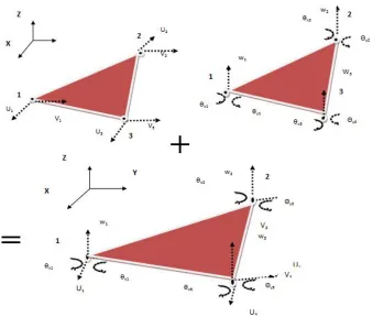
[image:7.612.136.475.438.726.2]Triangular stuck element says "suit"
Df = dégré of freedom.
6 Df for the element membrane + 9 Df for the element stick in flexion = 15 Df for the element stick complete.
The potential energy of deformation of an element sticks complete said “membrane + flexion” is the sum of the potential energy of the element membrane and of the element sticks in flexion (relation 1-d):
EPot =
{ } . [K]
él
. { }
The matrix of steepness [K]él, dimension (15X15), of the element sticks complete will appear as the assembly of the "partial" matrices of steepness of the element membrane and of the element stick in flexion.
MATERIAL
Means
The computer hardware used for this work consists of:
A printer Laser HP on 1020
A microcomputer HP with the characteristics and the following software:
Micro-processor Intel ® Corel (TM) 2 Duet CPU T5670 @1,80 Ghz Random access memory (RAM) of 1,93 Go
Hard disk of 149 Go
Microsoft Operating system Professional Windows XP 2002 Pack2 service The Microsoft software service (office) 2007
The software of calculation of structures Robot Millennium 17.0.
IT implementation
The main parts of the code of calculation of the software Robot millennium for the IT implementation are:
1st Part: Modeling of the structure on the software Robot millennium 17.0
- Geometrical Description of the model in CAD;
- Discreteness of the structure in finished elements (meshing and entrance of the data);
- Check of the geometrical modeling and the discreteness in elements finished by the phase of pre-treatment.
2nd Part: Calculation
- Constitution at first of the global matrix of the structure [K]str by assembly of the elementary matrices [K]él expressed in the global mark;
- The complete system of equations expressing the behavior of the structure spells: {F} = [K]str . {U} - Secondly, we rest suitably the structure (ensemble movements are not any more possible).
- Calculation of the free mentally retarded degrees of freedom {U*} and the actions of connection {Fl}.
3rd Part: Analysis of the results
- Check of the model finished elements recovering from the phase of post-treatment;
- Exploitation of the results: movements, deformations, constraints and validation of the results.
[image:8.612.91.520.589.669.2]RESULTS OF THE ANALYSIS
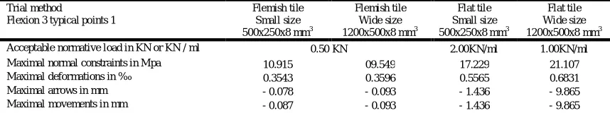
Table 4: recapitulation of the results of the maximal normal constraints and the movements maximal of flat tiles and Flemish tiles, Small and Wide size.
Trial method
Flexion 3 typical points 1
Flemish tile Small size 500x250x8 mm3
Flemish tile Wide size 1200x500x8 mm3
Flat tile Small size 500x250x8 mm3
Flat tile Wide size 1200x500x8 mm3 Acceptable normative load in KN or KN / ml 0.50 KN 2.00KN/ml 1.00KN/ml
Maximal normal constraints in Mpa 10.915 09.549 17.229 21.107
Maximal deformations in ‰ 0.3543 0.3596 0.5565 0.6831
Maximal arrows in mm - 0.078 - 0.093 - 1.436 - 9.865
Maximal movements in mm - 0.087 - 0.093 - 1.436 - 9.865
DISCUSSION AND INTERPRETATION
After examination of the results of the simulation, we notice that:
decrease gradually in the middle towards the supports where they nullify. The movements of the Flemish tiles follow the same logic with concentric circular layers around the knots where are applied loads. However, the maximal movements of the Flemish tiles are located on knots situated on the edges of the tile. Besides, the constraints developed in Flat tiles are more raised (36.6 % a 48.4 %) than those developed in the Flemish tiles. Consequently, with the same dimensions and the same conditions of requests, it turns out that the Flemish tiles are more resistant than Flat tiles.
For a Flat tile, the increase of the dimensions of the tile entrained an important increase of the constraints (18.4 %) and a strong increase of the movements (arrows) (85.4 %) in tiles which can pull the break of these tiles. On the other hand for the Flemish tiles, the increase of the dimensions of the tile is translated by a very low decrease of the constraints (0.3 %) and a low increase of the movements (6.5 %). What indicates that these tiles are more resistant. So, from the point of view resistance, Flat tiles, small size are advised with regard to the wide sizes whereas the Flemish tiles, the wide size are good indicated with regard to the small sizes.
Conclusion
According to the obtained results, we can hold on one hand that with the same dimensions of tiles and the same conditions in the limits, the Flemish tiles resist better than Flat tiles. On the other hand, for the choice of your tiles which will be sought by the flexion three ( 3 ) points, Flat tiles, small size are advised with regard to the wide sizes whereas the Flemish tiles, the wide size are good indicated with regard to the small sizes. So, to improve the quality of the choice of your tiles, we can make the same study for the flexion four (4) points. By this work we estimate to contribute to help the users to make a sensible choice of tiles to cover their works.
BIBLIOGRAPHICAL REFERENCES
BAGAN G. C., 2002. Contribution to the improvement of tiles in micro-concrete - characterization of materials and structures. Doctoral thesis of the University of Abomey Calavi. Sciences of materials.
BAILON J.P. & DORLOT J.M., 2000. Materials – Third edition. Polytechnic International Press. Montreal 2553007701. BRYS G., 1990. Tiles in vibrated mortar and fibro-mortier. Manuel of production. Technical report. BIT, Genève. COATES R. C., COUTIE M. G., KONG F. K., 1987. Structural Analysis. LOW PRICE EDITION.
GOURI D., TOUZOT G., 1987. A presentation of the method of the finished elements. MALOINE S. A. EDITEUR PARIS. GALLAGHER R. H., 1976. Introduction in the finished elements, EDITIONS PLURALIS.
FOUDJET E., 2009-2010. Courts of calculation of the structures by the method of finished elements, POST-GRADUATE DIPLOMA-SPI EPAC of the UAC in Benin.
GAY D. AND GAMBELIN J., 1999. Sizing of the structures – An introduction. Hermes Science Publications, Paris. 654 p. GRAM H.-E. and GUT P., 1991. SKAT-BIT : Quality control guidelines - fiber now micro computing concrete tiles , element 23. CRAVEUR J. C., 2001, Teaching the institute of the materials of Le Mans (ISMANS). Modeling of the structures: calculation by
elements finished with corrected problems, 2nd edition DUNOD, Paris. ISBN : 2 10 005547 X.
ODUL P., 1996. Roofs in tiles of mortar-Production and implementation–teaching aid. Preliminary version. BIT (Genève). 60 p. ROBOT MILLENNIUM. User guide version 17.0. Ed. 12-2003 / JR / VM.
SUP AERO, IMBERT J. F., 1979. Analysis of the structures by finished elements. CEPADUES EDITIONS.
TROMPETTE P., 1992. Mechanics of the structures by finished elements - static and dynamic. MASSON. ISBN 2-225-82732-X. YAMBA and al., 1997. Tiles in vibrated mortar normative document. LOCOMAT. Ministry of the infrastructures of the housing
environnement and the town planning Burkina Faso.
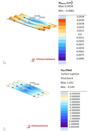
Figure 7: variations of the fields of movements and the fields of constraints of an Flat tile, small size..
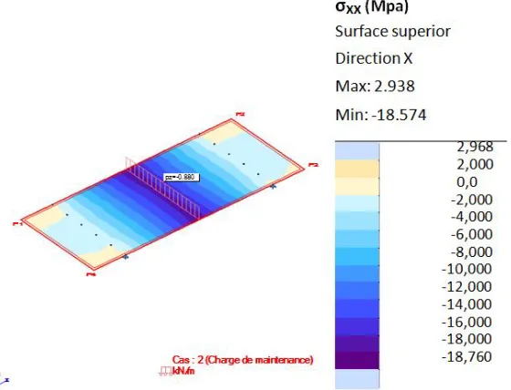
Figure 10: variations of the fields of movements and constraints of an Flat tile, wide size.