Performance Analysis of Multiple Access Techniques for
Broadband Power Line Communication System
Crallet Victor
The University of Dodoma
Bertha Shao
The University of Dodoma
Nixon Mtonyole
The University of Dodoma
ABSTRACT
Broadband over power lines is the way of providing internet services to customers using high frequency signals integrated in the power wiring. For uplink internet services data signals are modulated and coupled into the overhead power lines. For the downlink data signals are decoupled at the consumer’s premises. BPL can be a solution for people living rural area where there is electricity, since the cost of laying network cables and building the necessary infrastructure to every house is too high. BPL can serve to cut down the costs by eliminating the need for laying new infrastructure.
A successful deployment of BPL requires a MAC layer that can cope with powerline channel impairments. The purpose of MAC layer is to provide a multiple access scheme, resource sharing and traffic control functions. Multiple access schemes divide up to the total signaling resource into channels and then assign these channels to different users. To achieve that the transmission medium is divided along the time, frequency and/or code axes. There are various multiple access schemes, but in this paper FDMA and TDMA are the two multiple access schemes which are taken into consideration. Their performances under different channel conditions have been found. The channel conditions considered are low, medium and high disturbances. It was found that TDMA performs better than FDMA under all these channel conditions.
General Terms
Broadband Powerline Communications
Keywords
MAC, Performance analysis, PLC TDMA, PLC FDMA, Modeling, Simulation, Disturbances
1.
INTRODUCTION
Broadband over power lines is the way of providing internet services to customers using high frequency signals integrated in the power wiring. The internet signals are modulated and coupled into the overhead power lines. The signals are decoupled at the consumer’s premises [1]. Despite of the fact that broadband over power lines technology has been increased in the last few years, there is still the large area of the world that doesn’t have access to high speed internet, especially the developing countries like Tanzania.
Broadband over power lines is a technology that provides high-speed internet through the use of an electric power line to homes or offices. It can transmit data between 500kbps and up to a theoretical speed of 3Mbps over power lines to homes and offices which are almost equivalent to most Digital Subscriber Line (DSL) and cable modem transmission rates. To develop BPL technology, every home and office must be connected to the power grid and contains electrical wiring [2].
BPL can be a solution for people living in any rural area where there is electricity, since the cost of laying cables and building the necessary infrastructure to every house is too
high. BPL can serve to cut down the costs by eliminating the need for laying new infrastructure. By modifying the existing power grids with additional equipments, the BPL developers could join hands with power companies and internet providers to bring broadband services to everyone with access to electricity and hence increased understanding of the existing world.
2.
MULTIPLE ACCESS TECHNIQUES
A multiple access scheme establishes a method of dividing the transmission resources into accessible sections, which are used by multiple subscribers using various telecommunications services. A multiple access scheme is applied to a transmission medium (e.g. wireline or wireless channel) within a particular frequency spectrum, which can be used for information transfer equation [3].
Multiple access techniques divide up to the total signaling resource into channels and then assign these channels to different users. The most common ways to divide up the transmission medium are along the time, frequency and/or code axes [4].
For multiuser communication links, resources of the channel have to be shared among a large number of users. In principle the multiple access is arranged multiple access protocol. Beside channel properties the choice of suitable access method is determined by requirements on data transmission in delay time, data amount and duty cycle [5].
Multiple access protocols can be divided into fixed access and random protocols as shown in the figure 2.2. Fixed access (conflict-free) protocols ensure that whenever a transmission is made on error-free channels, it will not be interfered by another transmission, and thus is successful. Conflict-free transmission can be achieved by allocating the channel to the users either statically or dynamically. Channel resources can be divided in terms of time, frequency or combination of time and frequency [6].
Figure 1: Classification of Multiple Access Schemes [6]
3.
PLC NETWORK STRUCTURE
The PLC network model considered consists of a base station (BS), which is located at a transformer station and connected to the backbone communication networks. The number of subscriber stations (SSs) is interconnected with each other and with the BS via the power line transmission medium. Figure 2 depicts the PLC Network considered in this investigation [8].
Figure 2: PLC Network [8]
The PLC access network is in the range of a low-voltage power supply network, as shown in fig. 2. It consists of;
BS, which is located at a transformer station and connected to a backbone telecommunication network, and
Number of subscriber stations (SSs), say N that are interconnected with each other and with the BS via the power lines.
Depending on the location, the transformer station distributes power to the covered low-voltage power supply network and receives power from a medium-voltage or high-voltage power supply network. When an SS is located near the BS, the communication can be organized directly between the SS and the BS; otherwise, one or more repeaters (RPs) may be embedded inside the network to compensate for signal attenuation. The RP is used for increasing signal strength when it falls below some predefined value.
The BS is an access point for the communication between a subscriber of the PLC network and a user of an external
network. Also it provides the communication between the subscribers inside the PLC network. The signal transmission directions in a PLC network include downlink from the BS to the SSs and uplink from an SS to the BS.
4.
MODELLING OF PLC MAC LAYER
In order to compare the performance of various multiple access schemes in accordance with QoS level, the model was developed. The model was then applied for performance evaluation of two multiple access techniques by using several uplink architectures. The multiple access techniques considered were TDMA and FDMA. In TDMA and FDMA the total channel capacity is divided into a fixed number of equal-capacity sub channels. In the model real-world parameter assumptions in the context of packet networks were taken into account. The real world parameters were useful during the performance analysis because they allowed the development of intuition about the effectiveness of the scheme.
The performance analysis of a communications network and the evaluation of QoS parameters, such as the relevant QoS parameter defined for this investigation, can be carried out by the following three methods [9];
Measurements,
Analytical modeling, and
Simulation modeling.
Simulation modeling is chosen as the primary analysis method in this investigation for the following reasons [9]:
Complexity of the MAC protocols,
Variety of applied disturbance and traffic models,
Fair performance comparison of different protocol solutions, and
The possibility of a detailed investigation of the protocol implementation.
5.
SIMULATION MODEL
The simulation model, selected for the investigation of MAC protocols in this study is as shown in fig.3 [10]; the model represents an FDMA/TDMA scheme. The model represents bi-directional transmission channels that connect network users/subscribers with the base station, which lead to the FDD mode, with symmetric division of data rates between uplink and downlink transmission directions. The transmission channels can be accessed by all network stations in the uplink transmission direction (shared medium) while the downlink is controlled by the base station. But for this study only the uplink is considered. This model is chosen because it provides the possibility for modeling [10];
Various disturbance types, which can be implemented to affect both single and multiple transmission channels and
Representation of different types of noise
[image:2.595.56.280.369.517.2]Figure 3: PLC Simulation Model [10]
In the model network stations represents subscribers and network stations and base stations implement all features of the investigated multiple access scheme. Though the generic simulation model is designed to represent the OFDMA/TDMA scheme, it can easily be adapted to represent a TDMA system as well as any combination of TDMA and FDMA methods [10].
5.1
Disturbance Modeling
The disturbances in PLC networks can be represented by an on–off model [11]:
OFF – the channel is disturbed and no transmission is possible, and
ON – the channel is available.
These two states are normally modelled by two random variables that represent inter-arrival times durations of the disturbances. In addition both random variables are always assumed to be negative exponentially distributed. However since the simulator for this study is Discrete-Event-Simulator (a channel can be in two states ON orOFF, time parameters are not considered), then all state are modelled by a single random variable.
The random variable represents the duration of a disturbance impulse with mean duration set to 100μs and it is assumed that the noise impulses with a duration shorter than 300μs do not cause transmission errors (e.g. owing to symbol duration, FEC etc). In this investigation, the disturbances are modelled independently for each transmission channel and following three disturbance scenarios are used in further investigations;
low disturbance network - 20μs mean duration of the impulses/disturbances,
medium disturbed network - 60μs mean duration of the impulses/disturbances,
heavily disturbed network - 100μs mean duration of the impulses/disturbances.
5.2
Subscriber Modeling
Network stations implemented in the simulation model (Fig.3) can be connected with a number of traffic models, to represent different telecommunications services or various service classes. Primary telecommunications services, Internet-based data transmission and telephony, representing a packet
switched and a circuit switched service respectively, can be implemented in the simulation model, as shown in Fig. 4. For data user models the packets (e.g. IP packets) from the data traffic source are delivered to the packet queue of the network station. Later, the packet is segmented into segments, which are stored in the transmission queue. Both packet and transmission queues can store a number of packet (or segments of a packet). So, a maximum of n user packets can be stored in the network station. After successful transmission of the packet, the next packet (if any) is moved from the packet to the transmission queue. Later, the reservation procedure is carried out for the new packet. The data source generates user packets according to an applied traffic model. After each packet generation, the data source calculates a time for the generation of a new packet. If the packet queue is occupied, the data source is stopped and it can deliver the new packet after the packet queue is empty again. This investigation implements a user model for telephony service only therefore user model for data will not be discussed further [11].
Figure 4: User models for data and telephony service [11]
For the implementation of the telephony service calls are generated in accordance with a traffic model for the telephony specified in fig. 4. The service provides circuit switched service (CS), without data reservation procedure such as that for the data service. It assumed that once the station generates data it is establishing the connection, therefore the no signalling procedure is carried out. The telephony service for this study applies in-band signalling due to the fact that packet generation is combined with connection requests.
5.3
Implementation and Parameters of the
Simulation Model
[image:3.595.323.543.290.487.2]Recent PLC access networks provide data rates of about 2Mbps. If the data rate of a transmission channel is set to 64 kbps, there will be approximately 30 channels in the system. Accordingly, the number of packet switched channels in the model is 15, which results in 960 kbps net data rate in the network (Tab. 3.1). The duration of a time slot provided by the TDMA scheme is set to 4 ms in the simulation and model. Within 4ms, a 64-kbps transmission channel can transmit a data unit of 32 bytes. Accordingly, the size of a data segment is also set to 32 bytes. It was also assumed that the entire segment is used for carrying payload.
Table 1 Simulation Model Parameters
Parameter Value
Number of channels 40-50
Channel data rate 64Kbps
Time Slot duration 4ms
Segment/Payload size 32 bytes The duration of a simulation run is chosen to correspond to the time needed for at least 10,000 events (generated packets) in the network.
In this study fixed-length messages are considered, therefore packets are transmitted by using FCFS. Fixed length messages and FCFS remove the need to implement buffers providing the environment that can be supported by the telephony service. The telephony service was employed to model the subscriber or users by Simulator applied in this study.
6.
PERFORMANCE EVALUATION
MAC layer is a common component in every telecommunications system with a shared transmission medium. There are various realizations of the MAC layer and its protocols that are developed for particular communications networks, depending on their specific transmission features, operational environment, and their purpose. PLC access networks are characterized by a special transmission medium (low-voltage power supply network) that provide limited data rates. Limited data rates are caused by the presence of noise in powerline channels causing disturbances for data transmission. To ensure the competitiveness with other access technologies, PLC has to offer a wide range of telecommunications services and satisfactory QoS.
A performance evaluation of various solutions for the multiple access techniques for MAC layer has to be carried out in network models with varying traffic conditions. To vary the network load, the number of network stations can be increased from 50 to 500. This results in a minimum average network load of 125 kbps and a maximum of 1.25 Mbps, in accordance with the internet traffic models. Another approach to the increase of the network load is a variation of offered traffic for individual network stations; for example, the offered network load of individual network stations can be varied from 2.5 to 25 kbps for a constant number of stations, which results in the same common offered network load, as in the first case. If the number of stations remains constant, the interarrival times of the user packets has to be reduced to increase the network load. That means, for a network load of 1.25 Mbps and 50 network stations, the inter-arrival time has to be set to 480 ms in the simple traffic model with rare requests and to 96 ms in the model with frequent requests. For this study network load variation was achieved by varying offered traffic for network stations, and then carried traffic and packet loss ratio were calculated for each offered traffic. The calculated values were used in determining and comparing the performance of TDMA and FDMA system.
6.1
Effect of Channel Disturbances on
FDMA System
To determine the influence of channel disturbances in FDMA multiple access techniques, two scenarios for each were considered. One being FDMA fixed number of channels under different channel disturbances. The other is FDMA variable number of channels under fixed channel disturbance. For variable number of channels, fixed channel disturbance the channel was considered to be heavily disturbed. While for variable disturbance, fixed number of channel the channel was considered under low, medium and heavy disturbance respectively. In all evaluations the PLC MAC layer model as it is already discussed was applied.
6.2
Fixed number of Channels
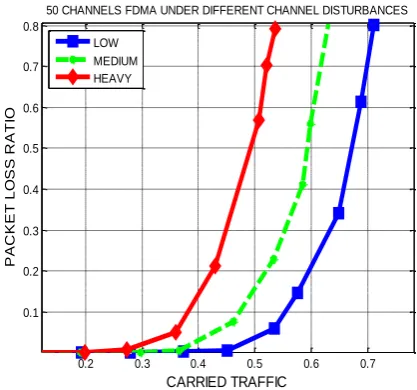
The PLC MAC layer with FDMA as a multiple access techniques was considered. The number of channels was set to 50, and then the channel disturbance was varied. The variations considered were low, medium and high channel disturbance. These disturbances are changed by varying the mean duration of the impulses or disturbances from 20μs to 100μs in an interval of 40μs. As it is stated in Sec. 3.3 60μs was the mean duration of the impulses or disturbances for this study. This implies that, bellow and above this value the channel presents low and high channel disturbances respectively. Thereafter the simulation was run while offered traffic and packet loss ratio are calculated. Fig. 5 shows the performance of the FDMA system with 50 channels at different channel disturbances. It is observed that for all channel disturbances the good performance is obtained when the channel presents low disturbances. For instance given the traffic load of 0.5 the packet loss ratio is 0.033, 0.15 and 0.51 for low, medium and high channel disturbances respectively. The good performance is obtained when the channel presents low disturbances because more packets are able to go through the channel.
Figure 5: 50 Channels FDMA under different conditions
6.3
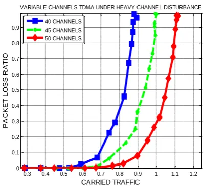
Variable number of Channels
The PLC MAC layer with FDMA as a multiple access techniques was considered. The heavy channel disturbance was selected, and then the number of channels was varied. The channels were varied from 40 channels to 50 channels in an interval of 5 channels. This was done to check if the increase of number channels as the effect on the packet loss ratio. Thereafter the simulation was run while offered traffic
0.2 0.3 0.4 0.5 0.6 0.7
0.1 0.2 0.3 0.4 0.5 0.6 0.7 0.8
50 CHANNELS FDMA UNDER DIFFERENT CHANNEL DISTURBANCES
CARRIED TRAFFIC
P
A
C
K
E
T
L
O
S
S
R
A
T
IO
and packet loss ratio are calculated. Fig. 6 shows the performance of the FDMA system with a heavy disturbed channel at different channel number of channels. It is observed that the good performance is obtained when the number of channels is 50. For instance given the traffic load of 0.4 the packet loss ratio is 0.1, 0.35 and 0.55 for a 50, 45 and 40 channels FDMA system respectively. The good performance is obtained when the number of channels is 50 because, there is a high probability of find a disturbance free channel in the system. Hence more packets are able to go through the channel.
Figure 6: Variable Channels under Heavy Channel Disturbance
6.4
Effect of Channel Disturbances on
TDMA System
To determine the influence of channel disturbances in TDMA multiple access techniques, two scenarios for each were considered. One being TDMA fixed number of channels under different channel disturbances. The other is TDMA variable number of channels under fixed channel disturbance. For variable number of channels, fixed channel disturbance performance the channel was considered to be heavily disturbed. In all evaluations the PLC MAC layer model as it is discussed earlier was applied.
6.5
Fixed number of Channels
The PLC MAC layer with TDMA as a multiple access techniques was considered. The number of channels was set to 50, and then the channel disturbance was varied. The variations considered were low, medium and high channel disturbance. These disturbances are changed by varying the mean duration of the impulses or disturbances from 20μs to 100μs in an interval of 40μs. As it is stated in Sec. 3.3 60μs was the mean duration of the impulses or disturbances for this study. This implies that, bellow and above this value the channel presents low and high channel disturbances respectively.
Thereafter the simulation was run while offered traffic and packet loss ratio are calculated. Fig. 7 shows the performance of the TDMA system with 50 channels at different channel disturbances. It is observed that for all channel disturbances the good performance is obtained when the channel presents low disturbances. For instance given the traffic load of 1 the packet loss ratio is 0.001, 0.05 and 0.25 for low, medium and high channel disturbances respectively. The good performance is obtained when the channel presents low disturbances because; there is a highest probability of finding
[image:5.595.65.274.195.379.2]the channel in good conditions. Hence more packets are able to go through the channel.
Figure 7: 50 channels TDMA under different channel disturbances
6.6
Variable number of Channels
The PLC MAC layer with TDMA as a multiple access techniques was considered. The heavy channel disturbance was selected, and then the number of channels was varied. The channels were varied from 40 channels to 50 channels in an interval of 5 channels. This was done to check if the increase of number channels as the effect on the packet loss ratio. Thereafter the simulation was run while offered traffic and packet loss ratio are calculated. Fig. 8 shows the performance of the TDMA system with a heavy disturbed channel at different channel number of channels.
It is observed that the good performance is obtained when the number of channels is 50. For instance given the traffic load of 0.8 the packet loss ratio is 0.033, 0.125 and 0.375 for a 50, 45 and 40 channels FDMA system respectively. The good performance is obtained when the number of channels is 50 because, there is a high probability of find a disturbance free channel in the system. Hence more packets are able to go through the channel.
Figure 8: Variable channels TDMA under heavy channel disturbances
0.1 0.15 0.2 0.25 0.3 0.35 0.4 0.45 0.5 0.55 0.6 0.1 0.2 0.3 0.4 0.5 0.6 0.7 0.8 0.9
VARIABLE CHANNELS FDMA UNDER HEAVY CHANNEL DISTURBANCE
CARRIED TRAFFIC P A C K E T L O S S R A T IO 40 CHANNELS 45 CHANNELS 50 CHANNELS
0.5 0.6 0.7 0.8 0.9 1 1.1 1.2 1.3 1.4 0 0.1 0.2 0.3 0.4 0.5 0.6 0.7 0.8
50 CHANNELS TDMA UNDER DIFFERENT CHANNEL DISTURBANCES
CARRIED TRAFFIC P A C K E T L O S S R A T IO LOW MEDIUM HEAVY
0.3 0.4 0.5 0.6 0.7 0.8 0.9 1 1.1 1.2 0 0.1 0.2 0.3 0.4 0.5 0.6 0.7 0.8 0.9
VARIABLE CHANNELS TDMA UNDER HEAVY CHANNEL DISTURBANCE
[image:5.595.325.526.531.715.2]7.
FDMA AND TDMA PERFORMANCE
COMPARISON
By comparing simulations of the FDMA and TDMA system it is observed that the performance of TDMA system under fixed number of channels, variable channel disturbances and fixed channel disturbance, variable number of channels surpasses that of FDMA. This is because for any configuration of channels TDMA has more number of channels. For example when the number of channels is 50 and channel disturbance is heavy TDMA system sustained a traffic load of 1 while the FDMA system sustained a traffic load of 0.452 with the same packet loss ratio. The packet loss ratio under this observation was 0.275. Given similar considerations it can be concluded that the TDMA system performs better, because reducing packet loss ratio means more capacity (A system can carry more users).
In TDMA the channels are divided along the time axis into non-overlapping channels, and each user is assigned a different cyclically-repeating timeslot. Therefore under the same number of channels, the actual number of channels in TDMA system is more compared to the FDMA system. This implies that there is a high probability of obtaining a disturbance free channel in the TDMA system than in the FDMA system. Hence more packets are able to go through the channel. But since TDMA channels occupy the entire system bandwidth which is typically wideband, some form of ISI mitigation is required. However, the cyclically repeating timeslots imply that transmission is not continuous for any user. Therefore, digital transmission techniques which allow for buffering are required. The fact that transmission is not continuous simplifies overhead functions such as channel estimation, since these functions can be done during the timeslots occupied by other users. Moreover in TDMA it is simple to assign multiple channels to a single user by simply assigning him multiple timeslots.
A major difficulty of TDMA, at least for uplink channels, is the requirement for synchronization among the different users. To maintain orthogonal timeslots in the received signals, the different uplink transmitters must synchronize such that after transmission through their respective channels, the received signals are orthogonal in time. This synchronization is typically coordinated by the base station or access point, and can entail significant overhead. Multipath can also destroy time-division orthogonality in both uplinks and downlinks if the multipath delays are a significant fraction of a timeslot. TDMA channels therefore often have guard bands between them to compensate for synchronization errors and multipath.
Further more in TDMA with cyclically repeating timeslots the channel characteristics change on each cycle. Thus, receiver functions that require channel estimates, like equalization, must re-estimate the channel on each cycle. When transmission is continuous, the channel can be tracked, which is more efficient. TDMA is used in the GSM, PDC, IS-54, and IS-136 digital cellular phone standards.
8.
CONCLUSION
In this study, the performance of two multiple access techniques were investigated. The PLC MAC layer simulation model developed by Hransica et. al., 2004 has been used to simulate a realistic PLC MAC layer.
To determine the influence of channel disturbances in FDMA/TDMA multiple access techniques, two scenarios for each were considered; one being FDMA/TDMA fixed number of channels under different channel disturbances and the other
is FDMA/TDMA variable number of channels under fixed channel disturbance. For variable number of channels, fixed channel disturbance the channel was considered to be heavily disturbed. While for variable disturbance, fixed number of channel the channel was considered under low, medium and heavy disturbance respectively. It was found that, the performance of TDMA system under fixed number of channels, variable channel disturbances and fixed channel disturbance, variable number of channels surpasses that of FDMA. For example when the number of channels is 50 and channel disturbance is heavy TDMA system carried a traffic load of 1 while the FDMA system carried a traffic load of 0.452 with the same packet loss ratio. The packet loss ratio under this observation was 0.275.
8.1
Recommendations
The results of this work have shown that the performance of TDMA system under different configuration surpasses that of FDMA. To maintain the same performance more channels should be employed in FDMA system. But in FDMA channels can be increased by increasing more carrier frequencies, this implies more bandwidth is required to carry the same traffic at the same packet loss ratio compared to TDMA system. Also besides the good performance provided by a TDMA system, the need for ISI mitigation, buffer requirements, synchronization and channel re-estimation on per slot basis complicates the TDMA communication system.
8.2
Suggestions for further research
For future work it is recommended researches for performance evaluation of other multiple access schemes such as the combination of OFDMA and TDMA (OFDMA/TDMA) must be done. Also the performance of CDMA considering direct sequence and frequency hopping must also be analyzed.
9.
REFERENCES
[1] Lucian Ngeze (2008), “Broadband over Powerline (BPL) Technology”, a seminar report, Department of Electronics and Communication Engineering, University of Kerala, Kerala, India.
[2] Hrasnica H., Haidine A. and Lehnert R., “Broadband Powerline Communications Networks-Network Design”, John Wiley & Sons, Ltd, 2004.
[3] Hrasnica H and Lehnert R, “Powerline Communications for Access Networks- Performance study of the MAC layer” III International Conference on
Telecommunications BIHTEL 2000
“Telecommunications Networks” – October 23-25, 2000 – Sarajevo, Bosnia and Herzegovina.
[4] Goldsmith A, Wireless Communications, Cambrige University Press, 32 Avenue of Americas, New York, NY 10013-2473, USA, 2005.
[5] Langfeld P, Zimmermann M and Dostert K, “Powerline Communication System Design Strategies for Local Loop Access”, International Symposium on Powerline Communications and its application (ISPLC2000), Limerick, Ireland; 5-7 April, 2000.
[7] Shensheng T. (2011), "Performance Analysis of Two Case Studies for a Powerline Communication Network", International Journal of Communication Networks and Information Security (IJCNIS Vol. 3, No. 2, August 2011).
[8] Bianchi, G., Tinnirello, I. and Conigliaro, G. (2003), Design and performance evaluation of a hybrid reservation-polling MAC protocol for power-line communications. Int. J. Commun. Syst., 16: 427–445. doi: 10.1002/dac.597.
[9] Hrasnica H., Lehnet R., “ Powerline Communications in Telecommunication Access Area (Powerline Communications im TK-Zugangsbereich)”, VDE World Microtechnologies Congress- MiCRO.tech 2000-ETG-Fachtagung und-Forum: Verteilungsnetze im liberalisierten Markt-September 25-27, 2000- Expo 2000, Hannover, Germany.
[10]Hrasnica H., “MAC Layer in Broadband PLC Networks- State of the Art, Solutions and Modelling”, November 5-8, 2000- Boston MA, USA.
[11] Hrasnica H. and Haidine A. “Modeling MAC layer for Powerline Communications Nertworks”, internet,
performance and control of networks systems, part of SPIE’s symposium on Information Technologies, Boston MA, USA; 5-8 November, 2000.
[12]Rappaport Theodore S. (2002),Wireless Communications, Principles and Practice, Prentice hall communications engineering and emerging technologies series, Prentice Inc., ISBN 0-13-042232-0.
[13]Bumiller G, “System Architecture for Power_Line Communication and Consequences for Modulation and Multiple Access”, GmbH, Groβhabersdorf, technical paper for ISPLC, 2001.
[14]Harada, H. and Prasad, R. (2002), Simulation and Software Radio for Mobile Communications, Artech House.
[15]Srikanth S., Kumaran V. and Manikandan C. (2010) “Orthogonal Frequency Division Multiple Access: Is it the Multiple Access of the Future?” AU-KBC Research Center, Presented at NCC, IIT Madras.
![Figure 1: Classification of Multiple Access Schemes [6]](https://thumb-us.123doks.com/thumbv2/123dok_us/8029124.768219/2.595.56.280.369.517/figure-classification-multiple-access-schemes.webp)
![Figure 4: User models for data and telephony service [11]](https://thumb-us.123doks.com/thumbv2/123dok_us/8029124.768219/3.595.89.271.68.267/figure-user-models-data-and-telephony-service.webp)