6
I
January 2018
Comparative Study of Conventionally Heat Treated
and Cryogenically Treated AISIM2-HSS Tool
Material by Evaluating Wear Performance
Dr. Lakhwinder Pal Singh1, Dr. Jagtar Singh2
1
Director, Tawi Engineering College, Shahpur Kandi, Pathankot, affiliated to P.T.U., Punjab.
2
Professor, Department of Mechanical Engineering, SLIET, Longowal, Sangrur, Punjab, India
Abstract: High Speed Steels (HSS) are commonly used tool materials in medium and small scale industries owing to their versatility and economic production of tools. Since its inception, HSS has undergone many modifications giving rise to several types of HSS tool materials for enhanced tool life. Cryogenic treatment of tool steels is a proven technology to increase wear resistance and extend intervals between component replacements for blades, bits, machining mills etc, hence the improved surface quality of the machined parts. It is a sub-zero thermal treatment generally given to ferrous tool materials. In this treatment the tool materials are subjected to below -186oC (-302oF) for different soaking period in well-insulated chambers by using liquid nitrogen (LN2). In this study sliding abrasion wear behavior tests were conducted as per ASTM G99-05 guidelines.
Frictional force as well as coefficient of friction at the interface between pin and disc was investigated during wear test. The shallow and deep cryogenically treated samples had shown less weight loss and better wear resistance as compared to conventionally heat treated at both the loads. Also, it was observed that the coefficient of friction at the interface between disc and pin was lesser in the case of deep cryogenically treated specimen.
Key Words: Cryogenic, Wear, Coefficient of friction, HSS, Sub-zero
I. LITERATURE REVIEW
Review of literature is a beneficial step in order to become familiar with the already established procedures and techniques for the particular research topic. It is also helpful in avoiding of duplication of work and wastage of time.
soaking period with contribution of 23.78%. The third major factor was cooling rate with contribution of 9.54%. The least significant factor acknowledged was tempering temperature with contribution of 2.74% whereas tempering period was found out to be trivial. Patil N. et al. (2014) conducted review to compare cryogenic treated tool (HSS) and untreated tool (HSS) and also to show new development in predicting tool life and tool wear. The tool life is increased by 19% for M2 grade HSS single point cutting tools. From SEM analysis, it is evident that refinement of carbides is more in case of cryogenically treated HSS tools in comparison to that of untreated tools. Vorozhtsov S. A. et al. (2015) presented the results obtained from investigations into the microstructure and physical-mechanical and electrical properties of cast aluminum-based alloys reinforced with nano-diamonds. It was found from the study that, addition of the diamond nano-particles had changed the structural parameters and also improved the mechanical properties of materials.
II. PROBLEM FORMULATION
Tool wear in machining is defined as the amount of volume loss of tool material on the contact surface due to the interactions between the tool and work piece. Specifically, tool wear is described by wear rate (volume loss per unit area per unit time) and is strongly determined by temperature, stresses, and relative sliding velocity generated at the contact interface. Metal cutting tools are subjected to extremely arduous conditions, high surface loads, and high surface temperatures arise because the chip slides at high speed along the tool rake face while exerting very high normal pressures (and friction force) on this face. The forces may be fluctuating due to the presence of hard particles in the component microstructure, or more extremely, when interrupted cutting is being carried out. Wear occurs even to the hardest of materials, including diamond, wear studies having focused on surface damage in terms of material removal mechanisms, including transfer film, plastic deformation, brittle fracture and tribo chemistry.
III. METHODOLOGY A. Cryogenic Treatment
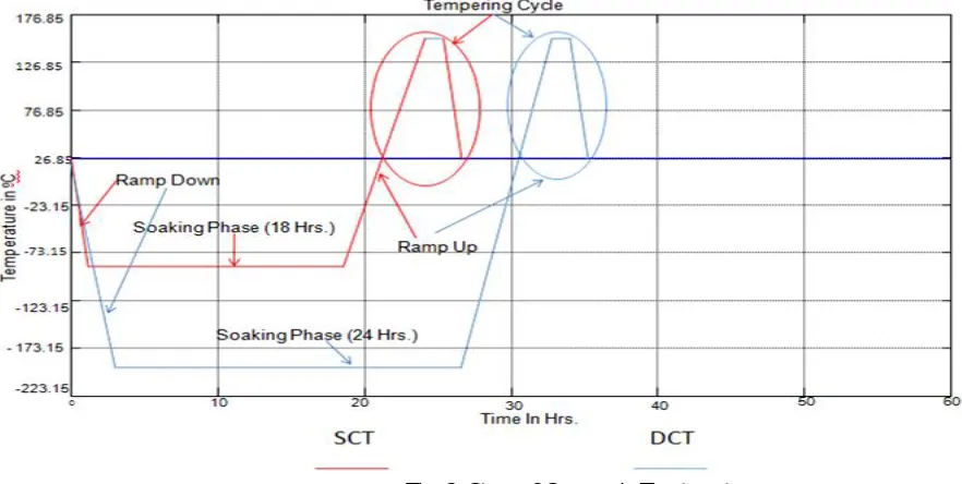
[image:3.612.82.523.425.647.2]Three different groups of specimens of AISIM2 tool steel were formed, one group was conventionally heat treated (CHT) with no extra treatment, second shallow cryogenically treated (SCT) and third deep cryogenically treated (DCT). Each group contains specimens for wear behavior testing. It is important to note that shallow and deep cryogenic treatment was executed after conventional heat treatment.
Fig. 2: Steps of Cryogenic Treatment
tempering at temperature of 150oC was done for group 2 & 3 specimens after cryogenic treatment. Cryogenic treatment on tools was conducted at Institute for Auto-Parts and Hand Tools Technology, Ludhiana, Punjab (India).
A recommended thermal cycle for this tool material was used, consisting of cooling to a temperature of -84◦C and -196◦C for SCT and DCT respectively, followed by heating to a temperature of +150oC for post tempering, Fig.4.2 illustrates this thermal cycle. B. Wear Testing
[image:4.612.211.403.460.630.2]Wear resistance tests were carried out on conventional heat treated specimens and cryogenic treated specimens. Shallow cryogenic treated specimens as well as deep cryogenically treated specimens were considered for wear studies. The wear test was conducted according to ASTM G99-05(2005) by using the wear testing machine with the Pin-on-Disc method. The Pin-on-Disc wear testing machine is shown in Figure 1. Small cylindrical pins of φ08 mm x 30 mm length were produced from AISIM2-HSS tool material.
Figure 1: Pin-on-Disc wear test machine
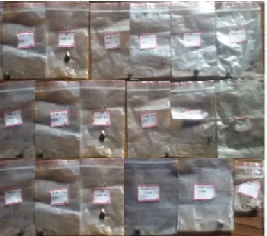
Total 18 pins were prepared for this purpose and shown hereby as per Figure 2. Ends of the pins were polished and cleaned with emery of 1000 grit size before loading them for wear study. Three different groups of pins were obtained, conventionally heat treated pins (CHT) with no extra treatment, shallow cryogenic treated pins (SCT) and deep cryogenically treated pins (DCT). Each group contained 6 pins. It is pertinent to mention here that shallow and deep cryogenic treatment was conducted after conventional heat treatment.
Figure 2: Specimens used for the wear behavior test
IV. EXPERIMENTATION A. Wear Behavior Testing
[image:5.612.98.516.155.433.2]The test for conventionally heat treated, shallow and deep cryogenically treated samples were performed at different sliding speed i.e. at 1.04, 1.57 and 2.08 m/sec at two load 30, 60 N while track radii was kept constant i.e. 50 mm.
Table 1: Coding of the samples
Sample no. Type of treatment Load (N) Sliding speed (m/s) Coding no. 1. Conventionally heat treated
(CHT)
30 1.02 CHT-13
2. 30 1.57 CHT-23
3. 30 2.08 CHT-33
4. Shallow cryo treated (SCT)
30 1.02 SCT-13
5. 30 1.57 SCT-23
6. 30 2.08 SCT-33
7. Deep cryo treated (DCT)
30 1.02 DCT-13
8. 30 1.57 DCT-23
9. 30 2.08 DCT-33
10. Conventionally heat treated (CHT)
60 1.02 CHT-16
11. 60 1.57 CHT-26
12. 60 2.08 CHT-36
13. Shallow cryo treated (SCT)
60 1.02 SCT-16
14. 60 1.57 SCT-26
15. 60 2.08 SCT-36
16. Deep cryo treated (DCT)
60 1.02 DCT-16
17. 60 1.57 DCT-26
18. 60 2.08 DCT-36
The different rotational speeds (400, 600, 800 rpm) of disc for all the cases was adjusted to maintain linear sliding velocity at respective value 1.04, 1.57 and 2.08 m/sec. A variation of ± 5-disc rpm is noticed in the disc speed. Three different group of pins in which six conventionally heat treated, six in each shallow and deep cryogenically treated. Each pin of different treatment operates at different rpm. Accordingly, pins were coded for proper identification as mentioned in Table 1.
1) Cumulative weight loss :Weight loss of each sample was measured after 5,5,5, 10,10,10,15 minutes to conclude the wear loss. The pin was required to remove from the holder to cool down at room temperature. It is efficiently brushed after each run to remove wear debris, weighed and then fixed in holder to keep the orientation of the sliding surface remains unchanged. The weight of the samples was measured before and after the test to calculate the wear loss from cumulative weight loss
2) Coefficient of friction and frictional force: The coefficient of friction (COF) is determined from the frictional force which can be directly measured from the wear testing machine and normal load which has been plotted against the sliding time, it gives the frictional behavior of all the three different types of samples. It is calculated by the following equation:
COF = ( )
( )
Where frictional force can be directly measured from wear testing machine (N) and applied load is the load applied during wear test. V. RESULTS AND DISCUSSIONS
A. Wear Testing
B. Cumulative Weight Loss (Clw), Coefficient Of Friction And Frictional Force
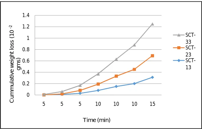
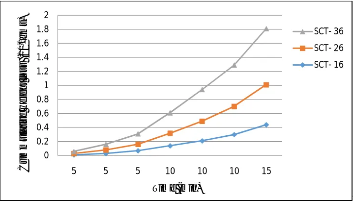
[image:6.612.129.484.211.422.2]It is observed from the Figures 3 to 8 that shallow and deep cryogenically treated samples have shown less weight loss and better wear resistance as compared to conventionally heat treated samples at a load 30N. Figure 3 to 5 showed that shallow cryogenically treated sample at sliding speed 2.08 m/sec has only marginal increase in cumulative weight loss as compared with deep cryogenically treated. The corresponding CWL for deep cryogenically treated is almost two times less as compared to conventionally heat treated sample on the same speed. It is further observed from the Figure 6 to 8 that shallow and deep cryogenically treated samples have shown less weight loss and better wear resistance as compared to conventionally heat treated at a load 60N. Results indicated that shallow cryogenically treated sample at sliding speed 2.08 m/sec has only marginal increase in cumulative weight loss when compared with deep cryogenically treated. The corresponding CWL for deep cryogenically treated sample is almost two times less as compared to conventionally heat treated sample on the same speed.
Figure 3: Wear behavior of CHT samples (sliding velocity 1.04m/sec, 1.57 m/sec, 2.08 m/sec and load 30N)
Figure 4: Wear behavior of SCT samples (sliding velocity 1.04m/sec, 1.57m/sec, 2.08 m/sec and load 30N)
0 0.2 0.4 0.6 0.8 1 1.2 1.4 1.6 1.8 2
5 5 5 10 10 10 15
C u m m u la lt ive w e ig h t lo s s (1 0 -2 g m s ) Time (min) CHT-33 CHT- 23 CHT- 13 0 0.2 0.4 0.6 0.8 1 1.2 1.4
5 5 5 10 10 10 15
[image:6.612.129.483.460.686.2]Figure 5: Wear behavior of DCT samples (sliding velocity 1.04m/sec, 1.57m/sec, 2.08 m/sec and load 30N)
Figure 6: Wear behavior of CHT samples (sliding velocity 1.04 m/sec, 1.57 m/sec, 2.08m/sec and load 60N)
Figure 7: Wear behavior of SCT samples (sliding velocity 1.04 m/sec, 1.57 m/sec, 2.08 m/sec and load 60N)
0 0.2 0.4 0.6 0.8 1
5 5 5 10 10 10 15
C u m m u la ti ve w e ig h t lo s s (1 0 -2g m s ) Time (min) DCT-33 0 0.5 1 1.5 2 2.5 3
5 5 5 10 10 10 15
C u m m la ti ve w e ig h t lo s s (1 0 -2g m s ) Time (min) CHT- 36 CHT- 26 CHT- 16 0 0.2 0.4 0.6 0.8 1 1.2 1.4 1.6 1.8 2
5 5 5 10 10 10 15
[image:7.612.127.486.498.703.2]Figure 8: Wear behavior of DCT samples (sliding velocity 1.04 m/sec, 1.57 m/sec, 2.08 m/sec and load 60N)
Table 8: Cumulative weight loss, coefficient of friction and frictional force at interface between Pin and Disc
Load Sliding velocity
m/sec
CHT SCT DCT
Wt. loss (10-2)
gm Frictio-nal force Coeff. of friction (µ)
Wt. loss (10-2)
gm Fricti- onal force Coeff. of friction (µ) Wt. loss (10-2)
gm Fricti- onal force Coeff. of friction (µ) 30N
1.04 0.40 13.2 0.44 0.31 14.0 0.47 0.21 12.0 0.40 1.57 0.58 12.0 0.40 0.38 8.6 0.29 0.28 4.8 0.16 2.08 0.79 10.2 0.34 0.56 6.9 0.23 0.38 3.6 0.12 60N
1.04 0.60 8.6 0.14 0.44 5.8 0.097 0.32 2.4 0.04 1.57 0.81 10.6 0.28 0.57 7.4 0.12 0.41 4.2 0.07 2.08 1.20 9.8 0.16 0.80 9.1 0.15 0.63 7.8 0.13
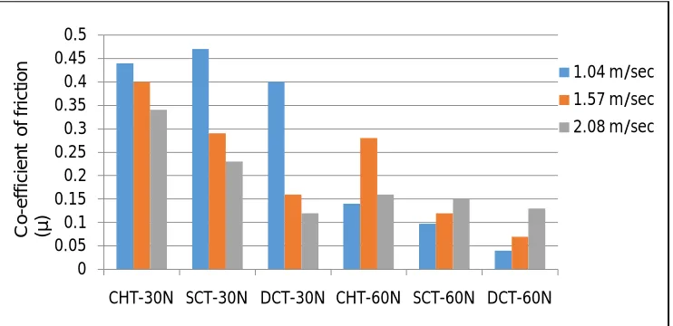
Coefficient of friction (COF) often symbolized by the Greek letter µ is a dimensionless scalar value which describes the ratio of the force of friction between two bodies and the force pressing them together. Coefficient of friction can be measured on a tribometer. A tribometer is also used to measure other tribological quantities such as wear volume and frictional force. The values of cumulative weight loss, coefficient of friction and frictional force (Figure 9 and 11) at Interface between Pin and Disc was recorded and mentioned in Table 10.
Figure 9: Effect of speed and load on co-efficient of friction
0 0.5 1 1.5
5 5 5 10 10 10 15
C u m m u la ti ve w e ig h t lo s s (1 0 -2g m s ) Time (min) DCT- 36 DCT- 26 DCT- 16 0 0.05 0.1 0.15 0.2 0.25 0.3 0.35 0.4 0.45 0.5
CHT-30N SCT-30N DCT-30N CHT-60N SCT-60N DCT-60N
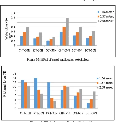
[image:8.612.123.494.536.716.2]Figure 10: Effect of speed and load on weight loss
Figure 11: Effect of speed and load on frictional force
The Figure 9 assist to infer that coefficient of friction (µ) at the interface between pin and disc was found to be lesser in the case of deep cryogenically treated pins than conventionally heat treated pins. For instance, at a velocity of 1.04 m/sec and a load of 60N, µ
value is 3.5 times in the case of CHT pin than DCT pin. At a load of 60N and speed of 1.57 m/sec the ratio of μ between CHT and DCT pin is 4 and it reduces to 1.23 with the further increase in velocity to 2.08 m/sec. The ratio of µ between CHT and SCT at the same load and all the three speeds 1.04, 1.57 and 2.08 m/sec and same load of 60N is 1.44, 2.33, 1.06 and between SCT and DCT it is 2.4, 1.7, 1.15 respectively. The corresponding force of friction has also been found less in case of DCT samples as compared to CHT. It is clearly evident that tribological conditions prevailing at the interface between pin and disc plays significant role on the coefficient of friction and consequently on the frictional force acting at the interface. It is also very sensitive to sliding velocity. Also it was observed that the coefficient of friction at the interface between disc and pin was 30 – 55 % lesser in the case of deep cryogenic treated specimen. It was observed from Figure 10 that the deep cryogenic treatment improves the wear resistance of the sample for about 50%. This improvement is a consequence of retained austenite elimination, better uniform carbide distribution. It also reveals that with increasing the sliding speed, the wear rate increases gradually.
VI. CONCLUSION
The shallow and deep cryogenically treated samples have shown less weight loss and better wear resistance (50-55%) as compared to conventionally heat treated. The cumulative weight loss for deep cryogenically treated M2-HSS sample is almost two times less as compared to conventionally treated sample on different wear conditions. Also it was observed that the coefficient of friction at the interface between disc and pin was 30 – 55 % lesser in the case of deep cryogenic treated specimen. It was observed that the deep cryogenic treatment improves the wear resistance of the sample for about 50%. Fine precipitates of carbides formed during deep cryogenic treatment increased the wear resistance by dispersion hardening effect.
0 0.2 0.4 0.6 0.8 1 1.2 1.4
CHT-30N SCT-30N DCT-30N CHT-60N SCT-60N DCT-60N
1.04 m/sec 1.57 m/sec 2.08 m/sec
W
e
ig
h
t l
o
s
s
(1
0
-2)g
m
0 2 4 6 8 10 12 14 16
CHT-30N SCT-30N DCT-30N CHT-60N SCT-60N DCT-60N
1.04 m/sec 1.57 m/sec 2.08 m/sec
Fr
ic
ti
o
n
al
fo
rc
e
(N
REFERENCES
[1] ASTM G99-05, 2005. Standard test method for wear testing with a Pin-on-Disk apparatus, ASTM book of standards, West Conshohocken, PA, United States. 03.02.
[2] Feyzullahoglu E., Zeren A., Zeren M., 2008. Tribological behavior of tin‐based materials and brass in oil lubricated conditions, Materials and Design, 29(3) :
714–720.
[3] Gill S.S., 2012. Optimization of cryogenic treatment to minimize the flank wear of AISI M2 high speed steel tools by Taguchi technique, Journal of Engineering Research and Studies, 3(2), 28-33.
[4] Khrais S. and Lin Y.J., 2007. Wear mechanisms and tool performance of TiAlNPVD coated inserts during machining of AISI 4140 steel. Wear, 262: 64–69. [5] Korkut I, Kasap M, Ciftci I, Seker U., 2004. Determination of optimum cutting parameters during machining of AISI 304 austenitic stainless steel, Materials &
Design, 25(4): 303-305.
[6] Kumar S., Mondal D.P., 2000. Effect of microstructure and chemical composition ofhardfacing alloys to abrasive wear behavior. Journal of Material Processing Technology, 9 : 649-655.
[7] Patil N., Kakkeri S., Sangamesh, 2014. Effect of cryogenic treated and untreated tool on its tool life-Review, International Journal of Science and Research (IJSR), 3(8) : 141-145.
[8] Vorozhtsov S.A., Khrustalyov А.P., Eskin D.G., КulkovS.N.,Baena N.A. 2015. Thephysical-mechanical and electrical properties of cast aluminum- based alloys reinforced with diamond nanoparticles, Russian Physics Journal, 57(11) : 1485-1490.
[9] Zhirafar S., Rezaeian, A. Pugh M., 2007. Effect of cryogenic treatment on the mechanical properties of 4340 steel. Journal of Materials Processing Technology,
AUTHOR’S BIOGRAPHY
Dr. Lakhwinder Pal Singh has 23 years of teaching, research and industrial experience and presently working as Director atTawi Engineering College, Pathankot, Punjab, India. He did his B.E Mechanical in 1993 from Amravati University (M.S.), M.E. in Industrial Engineering from Guru Nanak Dev Engineering College, Ludhiana, Punjab under Punjab Technical University, Jalandhar and Ph.D Mechanical Engineering from SLIET (Deemed University under MHRD, Govt. of India), Longowal, Sagrur, Punjab, India. He has published more than 16 research papers in international/ national journals and proceedings of international and national conferences. His research interests are manufacturing, industrial engineering and materials technology. E-mail: [email protected]