Data Integration
vom Fachbereich Informatik
der Technischen Universit¨
at Kaiserslautern
zur Verleihung des akademischen Grades
Doktor der Ingenieurwissenschaften (Dr.-Ing.)
genehmigte Dissertation von
Dipl.-Inf. Thomas J¨
org
Dekan des Fachbereichs:
Prof. Dr. Arnd Poetzsch-Heffter
Berichterstatter:
Prof. Dr.-Ing. Stefan Deßloch
Prof. Dr.-Ing. Bernhard Mitschang
Datum der wissenschaftlichen Aussprache:
18.01.2013
Data integration aims at providing uniform access to heterogeneous data, man-aged by distributed source systems. Data sources can range from legacy sys-tems, databases, and enterprise applications to web-scale data management systems. The materialized approach to data integration, extracts data from the sources, transforms and consolidates the data, and loads it into an integra-tion system, where it is persistently stored and can be queried and analyzed.
To support materialized data integration, so called Extract-Transform-Load (ETL) systems have been built and are widely used to populate data warehouses today. While ETL is considered state-of-the-art in enterprise data warehousing, a new paradigm known as MapReduce has recently gained popularity for web-scale data transformations, such as web indexing or page rank computation.
The input data of both, ETL and MapReduce programs keeps changing over time, while business transactions are processed or the web is crawled, for instance. Hence, the results of ETL and MapReduce programs get stale and need to be recomputed from time to time. Recurrent computations over changing input data can be performed in two ways. The result may either be recomputed from scratch or recomputed in an incremental fashion. The idea behind the latter approach is to update the existing result in response to incremental changes in the input data. This is typically more efficient than the full recomputation approach, because reprocessing unchanged portions of the input data can often be avoided.
Incremental recomputation techniques have been studied by the database research community mainly in the context of the maintenance of materialized views and have been adopted by all major commercial database systems today. However, neither today’s ETL tools nor MapReduce support incremental re-computation techniques. The situation of ETL and MapReduce programmers nowadays is thus much comparable to the situation of database programmers in the early 1990s. This thesis makes an effort to transfer incremental recom-putation techniques into the ETL and MapReduce environments. This poses interesting research challenges, because these environments differ fundamen-tally from the relational world with regard to query and programming models, change data capture, transactional guarantees and consistency models. How-ever, as this thesis will show, incremental recomputations are feasible in ETL and MapReduce and may lead to considerable efficiency improvements.
Datenintegration erm¨oglicht einen einheitlichen Zugriff auf heteregene Daten, die in verteilten Quellen vorliegen. Das Spektrum von Datenquellen reicht dabeit von Legacy-Systemen, Datenbanken und Gesch¨aftsanwendungen bis hin zu Systemen zur Verwaltung sehr großer Datenmengen, wie sie im Web vorkom-men. Bei der sogenannten materialisierten Datenintegration werden Daten aus den Quellen extrahiert, transformiert und konsolidiert, und in das Integra-tionssystem geladen, wo sie f¨ur Anfragen und Analysen zur Verf¨ugung stehen. F¨ur die materialisierte Integration von Daten wurden sogenannte Extract-Transform-Load (ETL) Systeme entwickelt, die heute prim¨ar zum Laden von Data-Warehouse-Systemen eingesetzt werden. F¨ur die Transformation von Daten, die um ein Vielfaches gr¨oßer als klassische Gesch¨aftsdaten sind, beispiel-sweise die Berechnung eines Web-Suchindexes, wird in j¨ungerer Zeit ein neues Paradigma names MapReduce eingesetzt.
Die Eingabedaten von ETL und MapReduce Programmen ver¨andern sich kontinuierlich, daher muss ihr Ergebnis von Zeit zu Zeit neu berechnet wer-den. Wiederholte Berechnungen auf Grundlage sich ver¨andernder Eingabe-daten k¨onnen auf zweierlei Arten durchgef¨uhrt werden. Die Berechung kann entweder erneut vollst¨andig durchgef¨uhrt werden oder auf inkrementelle Weise erfolgen. Die Idee dabei ist es, ein zuvor berechnetes Ergebnis anhand der inkre-mentellen ¨Anderungen der Eingabedaten anzupassen. Dieser Ansatz ist in der Regel effizienter, da sich eine erneute Verabeitung unver¨anderter Eingabedaten h¨aufig vermeiden l¨asst.
Techniken zur inkrementellen Neuberechnungen wurden von der Datenbankge-meinde zur Wartung materialisierter Sichten untersucht und werden heute in kommerziellen Datenbanksystemen eingesetzt. Im Gegensatz dazu unterst¨utzen weder ETL noch MapReduce inkrementelle Neuberechnungen. Die Situation von ETL und MapReduce Programmierern ist daher vergleichbar mit der Situ-tation von Datenbankprogrammierern in den 1990er Jahren. Ziel dieser Arbeit ist es Techniken zur inkrementellen Neuberechnung in die Welt von ETL und MapReduce zu transferieren. Diese unterscheiden sich von klassischen Daten-banksystemen im Hinblick auf die verwendeten Anfragesprachen und Program-miermodelle, die Erfassung von Daten¨anderungen, sowie die transaktionalen Garantieen und Konsistenzmodelle. Wie diese Arbeit zeigen wird, ist eine
¨
Ubertragung von Sichtwartungskonzepten auf ETL und MapReduce dennoch m¨oglich und kann zu einer erheblich gesteigerten Berechnungseffiziens f¨uhren.
I would like to express my sincere gratitude to my advisor Prof. Dr.-Ing. Stefan Deßloch for his continuous support and guidance. Furthermore, I would like to thank Prof. Dr.-Ing. Bernhard Mitschang for taking the role of the second exam-iner, Prof. Dr. Arnd Poetzsch-Heffter for acting as chair of the PhD committee, and Prof. Dr. Reinhard Gotzhein for being on the PhD committee.
In the beginning of my PhD studies, I had the opportunity to gain invaluable insights into data integration in practice as an intern at IBM and I would like to express my gratitude to Dr. Albert Maier and Oliver Suhre for hosting me.
I am grateful to Michael Koch, Roya Parvizi, Marc Sch¨afer, and in particu-lar Johannes Schildgen who substantially contributed to my research through their Bachelor and Master theses. Furthermore, I want to thank my former fellow student Sebastian Baumg¨artner for explaining the ins and outs of SAP’s warehousing solutions to me.
My PhD studies would not have been nearly as much fun without my former “roommate” Dr. Nikolas Nehmer. I would like to thank him and my other col-leagues Dr. Sebastian B¨achle, Andreas B¨uhmann, Dr. Philipp Dopichaj, Dr. J¨ ur-gen G¨ores, Volker H¨ofner, Yong Hu, Joachim Klein, Dr. Yi Ou, Weiping Qu, Daniel Schall, Dr. Karsten Schmidt, Dr. Boris Stumm, and Dr. Andreas Weiner, who made this time enjoyable.
Thomas J¨org
1 Introduction 1
2 Materialized data integration – state of the art 5
2.1 Integration challenges . . . 5
2.1.1 Distribution . . . 6
2.1.2 Autonomy . . . 6
2.1.3 Heterogeneity . . . 7
2.1.4 Data quality . . . 9
2.2 Materialized data integration . . . 13
2.2.1 Materialized vs. virtual data integration . . . 14
2.2.2 Data integration phases . . . 15
2.2.3 Properties of data integration systems . . . 19
2.3 Integration systems . . . 22
2.3.1 Database replication . . . 22
2.3.2 Advanced database replication . . . 24
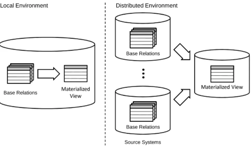
2.3.3 Materialized views . . . 25
2.3.4 Distributed materialized views . . . 33
2.3.5 Extract-Transform-Load . . . 36
2.4 Goals of this work . . . 47
2.5 Use cases . . . 48
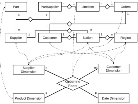
2.5.1 Use case: Data warehousing . . . 48
2.5.2 Use case: Data migration . . . 54
2.6 Related work . . . 55
3 An approach to incremental ETL processing 59 3.1 An ETL operator model . . . 61
3.2 Algebraic differencing of ETL jobs . . . 65
3.3 Research challenges in incremental ETL processing . . . 70
4 Optimization of incremental ETL jobs 73 4.1 Incremental recomputation issues in ETL . . . 73
4.2 ETL-adapted delta rules . . . 77
4.3 Projection pushing . . . 86
4.4 Magic ETL optimization . . . 88
4.4.2 Magic sets for non-recursive queries . . . 91
4.4.3 Magic Sets for incremental ETL jobs . . . 93
4.5 Chapter summary . . . 96
5 Incremental view maintenance using partial deltas 99 5.1 Change data capture . . . 100
5.2 Change data application . . . 105
5.3 The impact of partial deltas on view maintenance . . . 107
5.4 A generalized approach to algebraic view maintenance . . . 111
5.4.1 A formal model for partial deltas . . . 112
5.4.2 Dimension views . . . 113
5.4.3 Generalized delta rules for algebraic differencing . . . . 115
5.4.4 Projection . . . 118
5.4.5 Selection . . . 119
5.4.6 Join . . . 121
5.4.7 Set operators and aggregation . . . 125
5.4.8 Putting it all together . . . 126
5.5 Chapter summary . . . 126
6 Preventing incremental maintenance anomalies 129 6.1 Maintenance anomalies . . . 129
6.2 Preventing maintenance anomalies . . . 133
6.2.1 Properties of operational data sources . . . 134
6.2.2 Preventing delta inconsistencies . . . 136
6.2.3 Anomaly-Proof Incremental Recomputations . . . 138
6.3 Chapter summary . . . 142
7 Incremental recomputations in MapReduce 143 7.1 MapReduce and related technologies . . . 144
7.1.1 MapReduce . . . 145
7.1.2 Google file system . . . 147
7.1.3 Bigtable / HBase . . . 147
7.2 Related work . . . 148
7.3 Challenges of MapReduce view maintenance . . . 151
7.4 A case study . . . 152
7.4.1 MapReduce use cases . . . 153
7.4.2 HBase change capture . . . 155
7.4.3 The summary delta algorithm . . . 156
7.4.4 Incremental recomputation of word histograms and re-verse web-link graphs . . . 158
7.5 Evaluation . . . 167 7.5.1 View consistency . . . 167 7.5.2 Fault tolerance . . . 168 7.5.3 Performance . . . 168 7.6 Chapter Summary . . . 171 8 Conclusion 173 Bibliography 178
Recurrent computations over changing input data can be performed through one of two approaches. We may either fully recompute from scratch or, alterna-tively, recompute incrementally. The idea behind incremental recomputations is to consider incremental changes in the input data and derive incremental changes to the output data. That way, reprocessing unchanged portions of input data may be avoided and the efficiency may be improved considerably. The concept of incremental recomputations has been studied in the database research community mainly in the context of incremental maintenance of ma-terialized views. In this thesis, we argue that the same fundamental concept can be advantageously applied in other areas of data management, in partic-ular materialized data integration using Extract-Transform-Load (ETL) tools and MapReduce computations. In either area recurrent computations are very common; however, recomputations are typically done from scratch. We will show that incremental approaches are feasible in these areas as well and may lead to considerable efficiency improvements.
We briefly describe the concepts of materialized views, materialized data integration, and MapReduce to point out similarities and draw an analogy between them.
A database view is defined over one or more base tables by a given view definition and can thus be thought of as a derived table. Unlike standard database views, materialized views are pre-computed and stored physi-cally in the database much like a regular table. Materialized views can thus be queried very efficiently.
Data integration is an important concept in enterprise information agement. It addresses the need to jointly query and analyze data man-aged by heterogeneous source systems. Data integration techniques fall into one of two categories: virtual and materialized. The focus of this thesis is on materialized data integration, which consolidates data from heterogeneous sources in a central repository, usually referred to as data warehouse. For this purpose, data of interest is extracted from the het-erogeneous source systems, transformed to resolve data heterogeneity and improve data quality, and finally loaded into the data warehouse. Ma-terialized data integration is usually supported by middleware systems
referred to as Extract-Transform-Load (ETL) tools. The ETL process is typically repeated periodically.
MapReduce is a programming model and an associated framework for distributed data processing on large clusters of commodity hardware. In recent years, MapReduce became very popular in web-scale data manage-ment including web indexing or page rank computation. The MapReduce programming model is simple but powerful in the sense that MapReduce programs are easily parallelizable and thus highly scalable. MapReduce is layered on top of a distributed file system from which input data is read and to which output data is written.
From an abstract point of view, materialized views, materialized data integra-tion, and MapReduce computations show interesting similarities. To compute a materialized view, data is read from the base tables, transformed according to a user-defined view definition, and written back to the database system. To populate a data warehouse, data is read form heterogeneous source systems, transformed according to a set of ETL jobs, and written to the warehouse. To evaluate a MapReduce computation, data is read from the underlying dis-tributed file system, transformed according to user-defined map and reduce functions, and written back to the distributed file system.
Irrespective of apparent similarities, there is an important difference. When the underlying base tables of a materialized view are updated, the view is usually not recomputed from scratch but rather in an incremental fashion. In-cremental view maintenance has been intensively studied in database research and is supported by all major relational database products today. However, neither state-of-the-art ETL tools nor the MapReduce framework support in-cremental recomputations. In fact, ETL and MapReduce jobs are typically fully re-evaluated on a regular basis to obtain up-to-date results. We argue that the efficiency of recurrent computations in both ETL and MapReduce can vastly be improved by incremental approaches.
This thesis describes our work in transferring incremental view maintenance techniques into the world of materialized data integration and MapReduce. Doing so was by no means straightforward but posed a number of interesting research questions. This was due to the fact that ETL and MapReduce differ in many fundamental aspects from relational database systems that are typically used to manage materialized views.
Perhaps the most important difference exists between the query and trans-formation languages and underlying data models of these environments. In ETL, an industry-standard language such as SQL does not exist but ETL tools use proprietary operator models. ETL operators do not compare well to re-lational algebra operators but rather to operating system-provided command line utilities such as grep, sed, sort, etc. That is, ETL operators are rather
transformation semantics. Some ETL operator are highly specialized; all major ETL tools offer dedicated data cleansing operators, for instance.
MapReduce does not use a query and transformation language. The frame-work rather provides abstract methods, which need to be overwritten by MapRe-duce programmers using a general-purpose programming language. Further-more, MapReduce does not make use of the relational data model but uses a generic key-value model instead.
All previous work on incremental view maintenance is based on database query languages such as SQL or relational algebra and thus cannot be applied to either ETL nor MapReduce. Apart from the query and transformation languages ETL, MapReduce, and relational database systems differ in further aspects such as transaction handling, change data capture, data access paths, and fault tolerance. In the course of this thesis, we reconsider relational view maintenance techniques, adapt them as needed if possible or come up with new ideas.
art
In this chapter we will briefly review the state of the art in materialized data integration, which is the principal problem area of this thesis. In the Database Encyclopedia, the (more general) term “data integration” is used interchange-ably with the term “information integration” and is defined as follows [Hal09].
Information integration systems offer uniform access to a set of autonomous and heterogeneous data sources. Sources can range from database systems and legacy systems to forms on the Web, web services and flat files. The data in the sources need not be completely structured as in relational databases. The number of sources in an information integration application can range from a handful to thousands.
In the remainder of this section, we will discuss the challenges of data in-tegration in Section 2.1. This thesis is focused on a specific form of data integration, known as materialized data integration, which will be addressed in Section 2.2. Section 2.3 will introduce several alternative architectures for materialized data integration and point out strengths and weaknesses. We will conclude the chapter with a statement of goals to be achieved by this thesis in Section 2.4, discuss possible use cases for our approach in Section 2.5, and review related work in Section 2.6.
2.1 Integration challenges
In short, data integration aims at providing uniform access to non-uniform data sources. In this section we describe fundamental challenges of data in-tegration. The proposed classification scheme and the terminology are based on [G¨or09, LN06, SL90]. These authors distinguish three major challenges of data integration caused by the distribution, autonomy, and heterogeneity of data sources, which are discussed in Section 2.1.1, 2.1.2, and 2.1.3, respectively. We perceive data quality issues as fourth independent integration challenge and elaborate on this in Section 2.1.4.
2.1.1 Distribution
Intuitively, data is said to be distributed, if it is stored in different “locations”. Such locations can either bephysically distributed orlogically distributed or both.
Physical distribution means that data resides on physically separated and possibly geographically distributed machines. We call data technically dis-tributed, if it is physically distributed in a heterogeneous environment, i.e. man-aged by software systems of different kinds. Hence, technical distribution is a special case of physical distribution. Most often physical distribution is visible to the user, i.e. the user needs to be aware of the location of data to access it. However, physical distribution may also be transparent to the user. Distributed database systems and distributed file systems, for instance, use physical distri-bution to improve access times and provide fail-safety and, at the same time, offer uniform data access.
Logical distribution means that different storage locations, such as database tables, exist for semantically related data records. This situation often occurs when information systems with overlapping functionalities exist. For example, customer relationship management systems and billing systems, both store customer-related data. Note that logically distributed data is not necessarily physically distributed. The customer relationship management system and billing system may, for instance, store data in the same back-end database.
Both, physical and logical distribution may result in data redundancy, i.e. se-mantically similar data is being stored in different (physical or logical) loca-tions. Redundancy may be controlled, i.e. the storage system may keep re-dundant data in sync. This feature is typically provided by non-technical dis-tributed storage systems only. Uncontrolled redundancy is more common in data integration, because data to be integrated is typically managed by inde-pendent systems.
2.1.2 Autonomy
Source systems to be integrated are typically autonomous. That is, the systems are under separate and independent control. Those who control the systems are often willing to open up their systems for integration only if they retain control. Frequently, system owners are rather reluctant to changes with regard to both, the system itself and the system’s workload to limit the impact of the integration system on operational processing.
In literature, different forms of autonomy are distinguished. Design auton-omy refers to the freedom of a system to choose the data being managed (the universe of discourse) and the data representation with regard to data model, data formats, schema, naming, and constraints. Design autonomy is the
pri-mary cause of various forms of heterogeneity, which will be discussed in the following section.
Interface autonomy means that a system can freely decide which data access interfaces to provide. This includes the choice of supported query mecha-nisms (canned queries vs. arbitrary queries), query languages, protocols, and advanced features such as change data capture mechanisms. Other forms of autonomy, such as access autonomy and judicial autonomy [LN06] as well as association autonomy and execution autonomy [SL90] are not directly relevant in the context of this thesis and are therefore omitted here.
2.1.3 Heterogeneity
In [LN06], Leser and Naumann consider two information systems to be hetero-geneous, if they do not offer the exact same methods, models, and structures for data access. Resolving heterogeneity is a key task in data integration. Usually data sources are heterogeneous among each other; furthermore heterogeneity exists between the integration system and individual sources. Only the latter form of heterogeneity is relevant for data integration, because sources do not communicate directly.
In this section, different forms of heterogeneity are classified. Heterogeneity is considered only with regard to the structure of data, i.e. on the data model and schema level. Instance level integration challenges are summarized under the termdata quality and discussed in the subsequent section.
Technical heterogeneity Technical heterogeneity subsumes differences in the way data is accessed from the source systems. This includes differences in the communication protocols (e.g. JDBC or SOAP), data exchange formats (e.g. binary data or XML), query languages (e.g. SQL or XQuery), and query mechanisms (e.g. arbitrary queries or canned queries). Technical heterogeneity is closely related to technical distribution.
Syntactical heterogeneity Syntactical heterogeneity denotes differences in the representation of identical application concepts on the syntactic level. Com-mon examples are different byte orders of binary data (little endian vs. big endian), different character encodings (e.g. UTF-8, ASCII, or EBCDIC), or different separator characters for tabular data (tab-delimited or comma sepa-rated values). We furthermore subsume differences in the data types, domains, or physical units for representing identical application concepts under the term syntactical heterogeneity. This specific form of heterogeneity is referred to as domain heterogeneity in [G¨or09].
What is common to all forms of syntactical heterogeneity is that they can rather easily be resolved for data integration. It is straightforward to convert between character encodings or replace character separators, for instance.
Data Model heterogeneity Structured data adheres to a schema definition. While it is not mandatory, semi-structured data such as XML documents may adhere to a schema definition too. A schema is defined based on a data model that specifies a set of modeling concepts. Commonly used data models are the relational model, object-oriented models in various flavors, and the XML data model. Data model heterogeneity occurs when the data model of a source systems differs from the data model of the integration system. In this thesis, we focus on the integration of relational data and do not consider issues related to data model heterogeneity.
Structural heterogeneity Structural heterogeneity denotes differences in the representation of identical application concepts using the same data model. The design of a schema is influenced by various factors such as the range of real-world concept to be modeled, preferences of the schema designer, and the technical capabilities of the storage system.
Structural heterogeneity is very common in schemata based on non-minimal data models such as XML. In the XML data model the same real-world con-cept can often be expressed using different modeling concon-cept. For example, data items may be modeled either as elements or attributes. Furthermore, relationships may be represented by nesting related elements or by using refer-ences.
Structural heterogeneity may also occur in schemata based on the (more rigid) relational data model. A common form of structural heterogeneity in the relational model is different degrees of normalization. Operational databases are typically organized in at least third normal-form to avoid update anomalies. In contrary, analytical databases such as data warehouses are usually highly denormalized to reduce the number of joins required for query evaluation and improve query response times.
In the literature the term schematic heterogeneity is used to mean a special case of structural heterogeneity. Schematic heterogeneity denotes the usage of data model concepts from different meta-layers to model identical application concepts. In the relational model, for example, application concepts may be represented by relation names, attribute names, or attribute values. To resolve schematic heterogeneity so-called higher-order query languages have been in-troduced [LSS01, WR05]. This specific problem area is not in the scope of this thesis though.
Semantic heterogeneity Data in an information system does not have an in-herent meaning. In fact, it needs to be understood in its context to be useful. The context includes the name of schema elements, the relative position of schema elements, and knowledge about the application domain, just to name a few. Typically, the context is only partly available in machine-readable form. While the schema definition is usually available, knowledge about the applica-tion domain is most often not explicitly modeled.
Essentially, a schema element is nothing but a plain character string spec-ifying its name. Such a name characterizes a concept of the application do-main that is referred to as “intention” or “semantic” of the schema element. Semantic heterogeneity denotes differences in the relationships of names and intentions of schema elements. Common causes of semantic heterogeneity are different names having the same intention, referred to as synonyms, or equal names having different intentions, referred to as homonyms. Furthermore, dif-ferent names having somewhat related intentions that are neither disjoint nor identical are frequently found.
Resolving semantic heterogeneity is probably the biggest challenge of data integration. It is widely agreed that a strong artificial intelligence (AI) would be required to resolve it automatically and the problem is therefore considered to be AI-complete. Current approaches to resolve semantic heterogeneity are semi-automatic and only meant to support human experts in this task.
2.1.4 Data quality
In this section, we classify data quality problems, i.e. problems related to er-roneous and inconsistent data. Techniques to resolve data quality problems are referred to as data cleansing or data cleaning. Different classifications of data quality are found in literature and terminology is diverse. We will review classifications by Leser and Naumann, Rahm and Do, and Kimball and Caserta and discuss how they are related.
Leser and Naumann distinguish two kinds of data quality issues, based on how they can be resolved [LN06]. A data quality issue is referred to assimple, if it can be identified and resolved by examining a single tuple at a time. A so-called complex data quality issue, in contrast, can only be identified and resolved when multiple tuples are analyzed together. Leser and Naumann fur-thermore distinguish two successive phases of data cleansing. In the first phase, which is referred to as data scrubbing, simple data quality issues are resolved. Complex data quality issues are resolved in the second phase, which is referred to as duplicate elimination.
In [RD00], Rahm and Do classify data quality problems based on where they occur. The authors distinguish between single-source and multi-source prob-lems and between schema-related and instance-related probprob-lems. The
classi-Data Quality Problems Single-Source Problems Schema Level Lack of integrity constraints, poor schema design Instance Level Data entry errors
Multi-Source Problems
Schema Level Structural, semantic, and schematic het-erogeneity
Instance Level Overlapping, contra-dicting, and incon-sistent data
Figure 2.1: Classification of data quality problems after Rahm and Do [RD00]
fication scheme is shown in Figure 2.1. Single-source problems, as the name suggests, may already occur in a single data source. Multi-source problems oc-cur not until data from multiple sources is integrated. Single-source problems do, however, occur in the multi-source case too.
In a single data source, schema-related problems result from the lack of model-specific or application-specific integrity constraints. For data sources without schema support, such as files for instance, few restrictions can be imposed on what data can be entered and stored. Database systems enforce restrictions of a fixed data model and a user-defined schema. Furthermore, they allow for application-specific integrity constraints to be specified. Table 2.1 shows some common schema-related data quality problems in a single data source. If supported, schemata and integrity constraints can help to prevent these kind of problems in the first place.
Instance-related data quality problems relate to errors and inconsistencies that cannot be prevented at the schema level. Common problems of this kind for the single-source case are shown in Table 2.2. Note that missing values, misspellings, cryptic, embedded, and misfielded values, violated attribute de-pendencies, and word transpositions are simple data quality issues in the ter-minology of Leser and Naumann, whereas duplicate and conflicting records are complex data quality issues. Unlike the name suggests, simple issues are not always simple to resolve. Correcting misspellings or translating cryptic values requires domain-specific dictionaries. Embedded values require sophisticated parsing to separate out individual parts. As we will show in Chapter 4, data scrubbing operations are often computationally expensive.
Problem Reason Example
Illegal values A value is outside of its domain. dateOfBirth = 30.13.70
Violated attribute dependency
An explicit dependency between attributes is violated.
age = (current date - birth date) should hold
Uniqueness viola-tion
The same value appears multiple times in an attribute marked as being unique.
Referential integrity violation
A foreign key refers to a non-existent primary key.
Table 2.1: Single-source, schema-level data quality problems
Problem Reason Example
Missing values Attribute values may be NULL. While NULL values can be pre-vented by integrity constraint, user often bypass them by enter-ing dummy values.
phone = 9999-999999
Misspellings Manual data entry and OCR of-ten results in misspellings.
city = Kaiserlautern
Cryptic values and abbreviations
Abbreviations may obfuscate the meaning of values.
department = ’lgis’
Embedded values Multiple values may be stored in one attribute. It needs to be parsed to extract individual val-ues.
address = ’PO Box 3049, 67653 Kaiserslautern, Ger-many’
Misfielded values Values may be assigned incor-rectly.
city = ’Germany’
Violated attribute dependencies
An implicit dependency between attributes is violated.
zip = ’67655’, city = ’Bonn’
Word transpositions name1= ’J. Smith’,
name2= ’Miller P.’ Duplicate records Multiple tuples represent the
same real-world entity.
name1= ’J. Smith’,
name2= ’John Smith’ Conflicting records Duplicate records describe the
same real-world entity by differ-ent values.
Table 2.2: Single-source, instance-level data quality problems
Problem Reason Example
Contradicting val-ues
Values describing the same real-world entity may contradict.
dateOfBirth = 01.01.1970, age = 30
Unequal representa-tions
The same concepts may be rep-resented differently.
gender = ’F’, gender = 1
Unequal units Different measuring units may be used.
price = ’10,00’ (in USD)
price = ’10,00’(in EUR) Unequal precision The precision of measurement
not be the same.
length = 2h15min, length = 2h15min13sec
Unequal levels of ag-gregation
Similar data may be stored on different levels of aggregation.
Monthly sales vs. daily sales
Category A MUST be addressed at the source Category B BEST addressed at the source Category C BEST addressed at the integration system Category D MUST be addressed at the integration system
Figure 2.2: Classification of data quality problems after Kimball et al. [KC04]
Data quality problems, present in single sources, obviously occur in the multi-source case too. Moreover, the multi-multi-source case introduces additional issues. Schema-level problems arise from syntactical, structural, or semantic hetero-geneity of the sources to be integrated. Since Rahm and Do consider only structured data in the relational model, they do not discuss issues related to data model heterogeneity. Nevertheless data model heterogeneity also con-tributes to schema-level integration issues.
Similar to schema-level issues, single source instance-level issues also occur in the multi-source case. In fact, the likelihood of duplicate and potentially conflicting records (complex data quality issues) increases, because records re-ferring to the same real-world entity are frequently found in multiple sources. In contrast to the single-source case, these records are usually structured dif-ferently and overlap only partly. During data integration, records referring to the same real-world entity need to be identified and consolidated.
Apart from complex data quality issues, the multi-source case introduces specific simple data quality issues too. Common issues of these kind are shown in Table 2.3. Even when similar attribute names and data types are used, the same concept may be represented by different values across sources. Moreover, similar values may be interpreted differently, e.g. because different measure-ment units are used). Furthermore, information may be provided with different precision or at different levels of aggregation across sources.
In [KC04], Kimball and Caserta classify data quality issues based on where they are best addressed. They distinguish four categories as depicted in Fig-ure 2.2.
Category A issues are those issues that must be addressed at the data sources. Examples include missing information, dummy values, or “bogus” information. Most often, it is infeasible to recreate or correct such data if it has not been
captured correctly at the sources in the first place. Hence, category A issues cannot be resolved by the integration system. The integration system can only recognize these issues, remove any clearly bogus information, and report back the data quality problems to draw management focus on the source system defect. According to Kimball and Caserta, the majority of data-quality issues discovered during data warehouse projects fall into category A.
Category D issues are those issues that cannot be addressed at the data sources and thus, must be addressed at the integration system. Multi-source, instance-level data quality problems related to duplicates (i.e. complex data quality problems) clearly fall into this category. Obviously, duplicates across multiple sources can only be identified after the data has been gathered at the integration system.
The distinction between category B and C issues is less clear cut. Kimball and Caserta define category B issues to be those issues that are best addressed at the sources while this could, in principle, be done at the integration system too. Examples include misfielded values, violated attribute dependencies, and duplicate or conflicting records. Sometimes missing values also fall into this category rather than category A; a person’s gender can usually be derived from the first name, for instance.
Analogous to the definition of category B, category C includes those data quality issues that are best addressed at the integration system, while this could also be done at the sources. Multi-source, schema-level issues clearly fall into this category. Likewise, multi-source, instance-level issues that are not caused by duplicates (i.e. unequal representations, units, precision, and levels of aggregation) belong to category C. Resolving these data quality problems at the sources would necessitate schema changes and undermine the sources’ design autonomy.
Furthermore, certain single-source, instance-level issues, such as cryptic val-ues, abbreviations, and embedded values fall into category C. These kind of data quality issues are often “not an issue” form a source perspective. In fact, it may be very appropriate to store address data as single attributes at the sources, for instance. However, such embedded values should be separated into individual parts like street, zip code, city, and so on, during data integration. In this way, the integration system provides better support for analysis such as address matching or householding.
2.2 Materialized data integration
The purpose of integration systems is to resolve heterogeneity and data quality problems (to a certain extent) and provide a single-system image to users. There are two fundamental data integration approaches known as virtual and
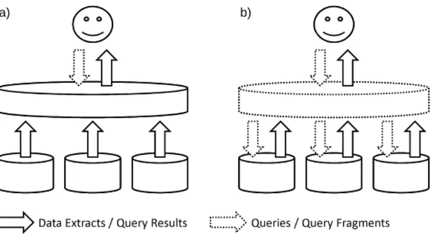
b) a)
Data Extracts / Query Results Queries / Query Fragments Figure 2.3: Materialized (a) and virtual (b) data integration
materialized integration, which are contrasted in Section 2.2.1. The focus of this thesis is materialized data integration. We identify desirable properties of materialized integration systems in Section 2.2.3. Subsequently, we review state-of-the-art architectures for materialized data integration, namely data replication systems, distributed materialized views, and Extract-Transform-Load (ETL) systems in Sections 2.3. We classify these integration architectures based on the properties defined in the Section 2.2.3 and point out strengths and weaknesses. Section 2.4 concludes the chapter with a statement of goals to be achieved by this thesis.
2.2.1 Materialized vs. virtual data integration
The key difference between materialized and virtual data integration is the place where data to be integrated is stored. In materialized integration, source data is copied to a central repository, whereas in virtual integration, all data remains in the source systems.
Figure 2.3 depicts materialized (a) and virtual (b) data integration on a high level of abstraction. Solid lines indicate the flow of data while dashed lines indi-cate the flow of queries. In materialized data integration, data is continuously moved from the sources to the integration system. Data movement is either performed periodically in an asynchronous manner or triggered by updates at the source systems. Query evaluation is done locally at the integration system and does not require any interaction with the sources.
provide an integrated view of source data [RS97]. To evaluate a user query, the integration system identifies query fragments that involve a particular source. Query fragments are send to the respective source systems and processed lo-cally. The fragment query results are sent back to the integration system where the overall query result is assembled.
In summary, materialized data integration is continuously performed in the background, while virtual data integration is performed on the fly at the time of query evaluation. Materialized integration systems generally achieve better query response times, because queries can be evaluated locally on pre-integrated data. Furthermore, the impact on the operational source systems is typically less strong and more predictable, because it is independent from the query workload. Likewise, computationally expensive integration tasks such as data cleansing have no negative impact on query response times as these tasks are performed off-line. In fact, data cleansing may be prohibitively expensive if done at the time of query evaluation and thus infeasible for virtual data inte-gration. Another advantage of materialized data integration is that historical data can be kept in the integration system even if it has been deleted at the sources. The biggest drawback of an asynchronous data integration pattern is that the integrated dataset is refreshed only periodically. Thus, the integra-tion system will usually not contain the most recent data, i.e. user queries are evaluated on more or less stale data.
This thesis is focused on materialized data integration. In the following, we will simply speak of data integration to mean materialized data integration.
2.2.2 Data integration phases
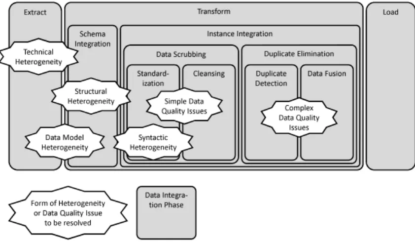
Materialized data integration can be divided into three consecutive phases: the extract phase, the transform phase, and the load phase. The acronym ETL, which is used to mean one class of integration systems, is derived from these three phases. We will take a closer look at ETL and other classes of systems for materialized data integration in Section 2.3.
The phase model proposed in this section is based on [BG04, KC04]. In this section, we will frequently refer back to the integration challenges (distribution, autonomy, heterogeneity, and data quality issues) discussed in the previous sec-tions. We will discuss which integration challenges are addressed by particular integration phases.
The overall data integration process is depicted in Figure 2.4. On the left-hand side, the figure shows the source systems storing data to be integrated. As companies evolve, they acquire or inherit various information systems to run their business, such as point-of-sale, inventory management, production control, and general ledger systems. Typically these systems are incompati-ble in the sense that they use different database systems, operating systems,
Transform
Extract Load
Schema
Integration Instance Integration
Data Scrubbing Duplicate Elimination Standard-ization Technical Heterogeneity Structural Heterogeneity Data Model Heterogeneity Cleansing Duplicate
Detection Data Fusion
Syntactic Heterogeneity
Simple Data
Quality Issues Data Quality Complex Issues
Form of Heterogeneity or Data Quality Issue
to be resolved
Data Integra-tion Phase
Figure 2.4: Phases of materialized data integration
hardware, or communication protocols. Hence, source systems are commonly heterogeneous (due to their design autonomy).
Extract The first step of data integration is the extraction of data of interest from the sources. To this end, the integration system must resolve technical heterogeneity. Integration systems differ in their ability to do so, as will be described in detail in Section 2.3.
Data extraction is performed by dedicated modules referred to as extractors. These extractors are tailored for a specific type of data source, such as database systems of different vendors, different file formats (e.g. flat files, COBOL copy books, or XML documents), or packaged applications (e.g. ERP or CRM sys-tems). Extractors have two main responsibilities. First, extractors allow the integration system to connect to a source system and read out its data. Apart from technical heterogeneity, the extractor may also need to resolve data model heterogeneity at this point (e.g. by flattening XML data).
Second, extractors may optionally be able to monitor a source system and capture data changes. This feature is referred to as Change Data Capture (CDC). A classification of CDC approaches and implementation alternatives will be given in Chapter 5. CDC mechanisms allow the integration system to extract changed data from the sources, commonly referred to as deltas, and update the integrated dataset as needed.
In [BG04] four strategies to trigger data extraction are distinguished. Ex-traction may be performed periodically using a pre-defined interval. ExEx-traction
may also be explicitly triggered by users. Furthermore, extraction may be per-formed in reaction to certain events, e.g. when a pre-defined number of changes has occurred. Finally, extraction may be done instantly when source data is changed, i.e. the deltas may be pushed to the integration system.
Transform The transformation phase can roughly be distinguished into schema integration and instance integration. These phases do not need to be strictly sequential but usually overlap to some extent.
In the schema integration phase, structural heterogeneity between the source schemata and the target schema is resolved. Unless done by the extractor, data model heterogeneity is also resolved at this point. Source systems are built for operational processing and typically use schemas in third normal-form. Inte-gration systems, such as data warehouses, however, are build for data analytics and denormalized schemas are more appropriate for this purpose [KC04]. For this reason, structural heterogeneity between source and target schemas is very common in data integration scenarios.
Schema integration may also involve the transformation of instance data, when multiple values are stored in a single attribute in the source schema. Recall that such attributes have been classified as data quality problem and referred to as “embedded values” in [RD00]. Embedded values are typically decomposed into their individual parts and stored in separate attributes in the data warehouse.
Apart from structural heterogeneity, semantic heterogeneity commonly exists between source and target schemas. However, semantic heterogeneity at the schema level must be resolved during the design of an integration solution. That is, semantic correspondences between source and target schemas need to be identified by developers in a process referred to as schema matching. There are research efforts to automate this task. However, at the present time schema matching tools work (at best) semi-automatic. The result of schema matching is called schema mapping or logical data map [KC04]. A schema mapping captures the semantic correspondences between source and target schema elements together with descriptions of the required transformations at the instance level. It hence resolves semantic heterogeneity at the schema level and provides the basis for the development of an integration solution.
The second step of the transform phase is referred to as instance integra-tion. The goal of instance integration is to homogenize data originating from different sources at the instance level and to identify and resolve data quality issues. When it comes to instance integration, the terminology used by dif-ferent authors is diverse. We will review and compare classifications proposed by Bauer and G¨unzel [BG04], Leser and Naumann [LN06], and Kimball and Caserta [KC04].
The first step in instance integration is standardizing data formats and rep-resentations, i.e. resolving syntactic heterogeneity. This step is referred to as normalization [LN06] or standardization [KC04].1 Data standardization may involve the following instance transformations [BG04]: Data type conversions, conversion between different data representations, standardization of string and date formats, unit and currency conversions, concatenation or separation of data values, computation of derived data, and data aggregation.
Subsequent to data standardization, there is a phase called data cleaning or data cleansing [BG04, KC04]. This phase addresses simple data quality problems, i.e. data quality problems that can be identified and resolved by examining a single tuple at a time. In Rahm and Do’s classification (see Sec-tion 2.1.4), such data quality problems are missing values, misspellings, cryptic values and abbreviations, misfielded values, and violated attribute dependen-cies. Leser and Naumann refer to the resolution of simple data quality issues as data scrubbing [LN06].
The final step of instance integration is referred to as duplicate elimination. The aim of duplicate elimination is to identify tuples that relate to the same real-world entity and consolidate related tuples. Duplicate elimination requires standardized and cleansed input data, i.e. simple data quality issues must have been resolved.
In the terminology of Leser and Naumann, duplicate elimination addresses so-called complex data quality problems, i.e. problems that can only be identi-fied and resolved when multiple tuples are analyzed together. Duplicate elim-ination can be subdivided into two consecutive steps. The identification of tuples related to the same real-world entity is referred to as duplicate de-tection [LN06], record matching [KC04], merge/purge problem [HS98], record linkage, or entity resolution [DF09]. The subsequent consolidation of tuples belonging to the same real-world object is referred to as data fusion [LN06] or surviving [KC04].
The measures taken to resolve data quality issues at the integration system are symptom-oriented. If the quality of source data is low, the integration system may not be able to improve the data quality to an acceptable level. Such data quality problems can only be addressed at their roots, i.e. directly at the source system [BG04].
Load The final phase of data integration is loading the transformed source data into the integration system for persistent storage. Depending on the frequency of data extraction, data may be loaded continuously or in batches.
1Bauer and G¨unzel use the term “data integration” (“Datenintegration” in German). This usage is misleading, because the term is usually used synonymous with information integration in literature, i.e. in a much wider sense. In this work, “data integration” is used in its common meaning.
Two types of loading can be distinguished, namely online and offline load-ing [BG04]. Durload-ing online loadload-ing, the integration system can be queried while loading is in progress. If loading is performed offline, the integration system is unavailable. Offline loading may have performance benefits, especially when data is loaded in large batches.
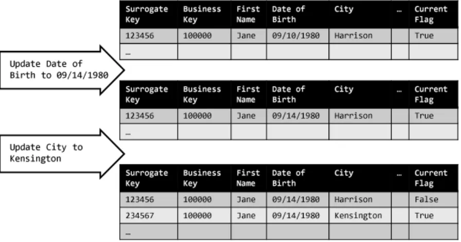
Integration systems with an emphasis on data analysis, such as data ware-houses, usually keep a history of data changes. That is, historical data is kept after it has been overwritten or deleted at the sources. Data warehouses usually employ a strategy known as “Slowly Changing Dimensions” for data historization, which will be discussed in detail in Section 2.5.1. Support for data historization needs to be built into the data loading module.
2.2.3 Properties of data integration systems
In this section, we introduce desirable properties of data integration systems. The set of properties will be used in the subsequent sections to classify existing integration systems and point out their strength and weaknesses.
In the beginning of this chapter, we discussed the challenges of data inte-gration. Obviously, an integration system should provide the infrastructure to overcome these challenges, at least to some extent. In our opinion, integration systems can well be characterized by four key properties, namely the degree of tolerable source distribution, the degree of tolerable source autonomy, the data transformation capabilities provided, and the ability to incrementally main-tain integrated data. These properties are described in greater detail in the following.
Degree of source distribution An integration system should at least be able to resolve physical data distribution, because data to be integrated is virtually always hosted by (geographically) distributed source systems. It is furthermore desirable to resolve technical distribution, i.e. integrate data that is hosted by systems of different kinds. Integration systems may allow for varying degrees of technical distribution. Some integration systems require their sources to be relational database systems, possibly from different vendors. Others are more flexible and allow for other kinds of systems, such as packaged applications or flat files for instance, to act as data sources too. Obviously, the stronger the assumptions about sources are, the more restricted the applicability of the integration system will be.
Degree of source autonomy It is a desirable property of an integration sys-tem to tolerate a large degree of source autonomy. Some integration syssys-tems tamper with the interface autonomy of source systems by imposing strong re-quirements. An integration system may require the sources to provide a specific
query interface or language such as SQL and tolerate some additional work-load, it may require the sources to participate in dedicated communication protocols, or it may demand for specific features such as change data capture mechanisms. Furthermore, design autonomy may be tampered with by enforc-ing schema changes at the source systems or additional constraints to improve local data quality, for instance.
To meet the integration system’s requirements, source systems may need to be adapted. However, such adaptations are often painful in practice. The reasons are twofold. First, system owners are usually eager to keep their au-tonomy and reluctant to change their systems. Changing a mature and proven system always entails the risk of introducing bugs and other problems. Second, system changes may be prohibitively complex. Legacy system, for instance, require significant re-engineering to be adapted to new requirements. Even worse, closed source packaged applications cannot be changed at all.
To sum up, an integration system should impose as few requirements as possible on the source systems and, at the same time, be able to exploit any interfaces and features currently provided by the system. That is, an ideal integration system should “make the most” of whatever the source systems are able and willing to offer.
Data transformation capabilities The transformation phase of materialized data integration has been discussed in Section 2.2.2. Recall that the trans-formation phase can roughly be divided into schema integration and instance integration. Schema integration is mainly about resolving structural hetero-geneity, i.e. restructuring source data to match the target schema of the in-tegration system. For this purpose, transformation capabilities comparable to the relational algebra (with aggregation) or SQL are sufficient. In fact, there are integration systems that use SQL to specify data transformations [Rau05]. Other systems use proprietary transformation languages. However, as recent studies suggest, these languages have a relational core [DHW+08, WCP09].
SQL-like transformation capabilities fall short of instance integration. Re-call, that instance integration can be divided into data standardizing, cleans-ing, and duplication elimination. Data standardization can be performed using simple string manipulation and format conversion functions. However, special-purpose transformation engines have been built for data cleansing and dupli-cation elimination that feature large domain-specific rule sets and ontologies. Only recently, integration system vendors started to integrate such engines into their products.
As said, the data transformation phase involves multiple tasks. However, integration systems may support only subsets of these tasks or may not fully support certain tasks. Details will be provided in Section 2.3. An ideal
in-tegration system should obviously provide the transformation capabilities to perform an “exhaustive” transformation.
Incremental maintenance In materialized data integration, data is extracted from the sources, integrated, and physically stored in the integration system. We will refer to the data content of the integration system as integrated dataset. Two phases of materialized data integration can be distinguished. A newly created integration system is initially empty; in the first phase, data is extracted exhaustively from the sources and loaded into the integration system. This phase is referred to as initial load.
When source data changes over time, the integrated dataset gets stale and needs to be maintained to regain consistency. Thus, maintaining the integrated dataset is the second phase of materialized data integration. While the first phase is performed only once, the second phase is an ongoing process. There are two fundamental approaches to maintain the integrated dataset such that it reflects the current state of the sources.
The first approach is referred to as full recomputation. The idea is to exhaustively extract and integrate the source data in much the same way as it was done at the initial loading phase. We will refer to the resulting dataset as re-integrated dataset. To perform a full recomputation, the integrated dataset can be dropped and replaced with the re-integrated dataset. However, any historical data, which is no longer available at the sources, will be lost. To keep historical data in the integration system, which is a common requirement in data warehousing, the re-integrated dataset needs to be compared to the current integrated dataset to deter-mine any data changes. These changes are then stored in the integration system, without deleting or overwriting any previous contents.
Assuming that only a small fraction of source data is changed during loading cycles, a full recomputation is rather inefficient. To improve the efficiency, the repeated extraction and integration of unchanged source data should be avoided. To this end, changes are captured at the sources and used to directly determine the induced changes in the integrated dataset. This approach is referred to as incremental recomputation or incremental maintenance. A full recomputation may be done in much the same way as the initial computation, i.e. the transformation logic can be re-used. However, this cannot be done for recomputing incrementally. In fact, the integration logic needs to be adapted for change propagation, making it more complex in general.
In summary, support for incremental maintenance is a desirable property of an integration system. However, this property is the harder to achieve, the
bigger the system’s data transformation capabilities are.
2.3 Integration systems
In this section, we will review different state-of-the-art integration systems. We propose to classify these systems into database replication systems, advanced database replication systems, materialized view systems, distributed material-ized view systems, and Extract-Transform-Load (ETL) systems, which will be discussed in Sections 2.3.1, 2.3.2, 2.3.3, 2.3.4, and 2.3.5, respectively. We will characterize each class of systems in terms of the desirable properties discussed in the previous section.
2.3.1 Database replication
Database replication means that several copies of relations or relation frag-ments are stored at multiple physically distributed locations [RG03]. The aims of database replication are increased availability of data in case of node or communication link failures and faster query evaluation due to higher data locality.
Replication schemes can be classified along two dimensions, namely the prop-agation strategy and the ownership strategy [GHOS96]. The propprop-agation strat-egy can either beeagerorlazy, also referred to as synchronous or asynchronous replication, respectively. Eager update propagation means that any update is applied to each associated replica as part of the modifying transaction. Hence, the update propagation involves a distributed transaction across multiple repli-cas. The overhead and limited scalability of distributed transaction processing makes eager or synchronous replication undesirable or even unachievable in many situations. Gray et al. show that the time to wait for locks and the probability of deadlocks grow cubically with the number of nodes in an eager replication system [GHOS96].
Asynchronous or lazy replication abandons distributed transactions and ap-plies updates to each replica in local transaction instead. Lazy replication achieves better scalability and is most often used in practice. However, the drawback is that different replicas of the same object may have different states at the same point in time.
There are two flavors of lazy replication depending on the ownership strat-egy used. In master or primary site replication, one replica of an object is designated the master replica. Only the master replica can be updated while all the others are read-only. Once the master replica has been updated the changes are propagated to other replicas. The alternative ownership strategy is referred to asgroup orpeer-to-peer replication and allows all replicas to be updated concurrently. It is thus possible for two transactions to update the
Figure 2.5: IBM DB2 SQL Replication overview [DB2a]
same object at different replicas and race each other to install their updates at the others. Such conflicts must be detected by the replication mechanism and reconciled so that updates are not lost.
Many commercial database replication offerings are available. As an ex-ample, we describe a replication solution provided by IBM DB2 called SQL replication [DB2a]. The overall architecture is depicted in Figure 2.5. DB2 SQL replication follows a lazy master replication scheme. It uses two programs referred to as Capture and Apply running on the source system and one or more target systems, respectively. The Capture program parses DB2 recovery logs and extracts committed changes to relevant source tables. These changes are written to a so-called change data (CD) table. It is possible to register just a subset of table columns for replication. In this case the Capture program ignores changes that affect unregistered columns only. The Apply program reads out the changes from the CD table and applies them to the replicated relations.
A subscription set associates source and target tables for replication and defines a mapping from source column names to target column names. A single source table can be associated with multiple target tables. For each source-target pair in a subscription set a predicate can be specified to select tuples for replication based on attribute values. Furthermore a scheduling strategy for data replication can be specified as part of a subscription set. DB2 SQL replication supports three alternative strategies. First, data replication may be performed at regular intervals. Second, it may be performed continuously,
i.e. as frequently as permitted by the current workload and the available system resource. Third, replication can be triggered by certain events signaled by an application or an user.
To sum up, we characterize database replication based on the desirable prop-erties of data integration systems introduced in Section 2.2.3. Database repli-cation techniques allow for physical distribution of source systems, however, technical distribution is often not supported. Replication solutions used to be vendor-specific and assume a homogeneous system environment. This has changed with the advent of a new class of systems we refer to as advanced replicationsystems, which will be discussed in the next section.
Database replication requires the source systems to be cooperative. Taking IBM SQL replication as an example, the source systems are required to switch to archive logging, run a capture program instance, and provide change data tables and further control tables. The source systems are thus forced to give up some of their autonomy.
The data transformation capabilities of traditional database replication are very limited. Typically replicated tables are one-to-one copies of their respec-tive source tables. However, IBM SQL replication allows to restrict replicated tables to a subset of the source columns. Furthermore, replicated tables may be restricted to a subset of source tuples based on a given filter predicate. These subset operations correspond to relational projection and selection, re-spectively, which characterizes the transformation capabilities.
The last desirable property for data integration is the ability to incrementally maintain an integrated dataset. Obviously, database replication supports the incremental maintenance of replicated tables.
2.3.2 Advanced database replication
Traditionally, the focus of database replication was on increasing data availabil-ity in case of failure and query performance. The next generation of database replication solutions broadened its focus to include data integration. We re-fer to this class of systems as advanced database replication systems. These systems are build for heterogeneous environments and provide stronger data transformation capabilities.
Advanced database replication solutions have been developed by DataMirror and GoldenGate, just to name a few. DataMirror has been acquired by IBM in 2006. The product was renamed as IBM InfoSphere Change Data Capture (CDC) and integrated in the IBM InfoSphere Information Server offering [Inf]. GoldenGate has been acquired by Oracle in 2009. Both products are similar in functionality. We will discuss advanced replication features taking InfoSphere CDC as an example.
including IBM, Microsoft, Oracle, Sybase, and Teradata. Like IBM SQL repli-cation, the system harvests database recovery logs to capture changes of in-terest. InfoSphere CDC follows a lazy group replication scheme and hence, allows for bidirectional replication. To reconcile possible conflicts two auto-mated strategies are provided. First, source updates may take precedence over target updates or vice versa. Second, larger values may take precedence over smaller ones or vice versa. The latter strategy is typically applied for times-tamped updates. Additionally, conflicts may be reconciled by application logic. InfoSphere CDC allows to transform data during replication in multiple ways. Similar to traditional database replication, a subset of source columns may be chosen for replication and particular source tuples may be selected based on a filter predicate. These operations are similar to relational projection and selection, respectively. Furthermore, InfoSphere CDC allows for value trans-formation. Specific source values may be replaced during replication based on user-defined value mappings. Abbreviations may be translated to an expanded form in this way, for instance. Additionally, InfoSphere CDC provides a set of so-called column functions to convert string, date, and time values. XML column values may be transformed using a subset of the XPath language.
Another interesting feature of InfoSphere CDC is so-called “one-to-many row consolidation”. It allows to use a special kind of source table referred to as lookup table. Columns from both, regular source tables and lookup tables can be matched to columns of a single target table. During replication, source tu-ples are combined with lookup tutu-ples based on the lookup tutu-ples’ primary key values. Thus, InfoSphere CDC essentially computes an inner equi-join between source and lookup tables. Updates at either of these tables are propagated to the target table. However, there are some restrictions. Deletions at the lookup table are not reflected at the target table. Furthermore, lookup ta-bles and source tata-bles must reside at the same system, i.e. joins across system boundaries are not supported. Such cross-system joins pose interesting syn-chronization problems, which will be discussed in Section 2.3.4 on distributed view maintenance.
In summary, advanced database replication enhances traditional database replication mainly in two aspects. First, a range of database systems from different vendors may be tied together. Thus, technical distribution is resolved to a larger degree. Second, additional data transformation capabilities are provided, including value transformations and local equi-joins.
2.3.3 Materialized views
A view is a special kind of relation that is derived from a set of base rela-tions. Abstractly, a view can be regarded as a transformation function that maps base tuples to view tuples. The transformation function is typically
re-computed every time the view is referenced in a query. Alternatively, a view can be pre-computed and persisted; it is then referred to asmaterialized view. Materialized views provide efficient access, because they do not need to be com-puted at query evaluation time. Furthermore index structures may be built on materialized views.
However, the price to pay is the need to update materialized views upon updates to the base relations. This process is referred to asview maintenance. Most often it is wasteful to maintain a materialized view by recomputing it from scratch. Assuming that updates affect just a small part of the base data, it is often more efficient to compute only the changes in the view to update its materialization. This approach is referred to asincremental view maintenance. Materialized views are not generally regarded as data integration technique, because the view and the base relations are managed by the same database system. We mention materialized views here for two reasons: First, the con-cept has been generalized to a distributed environment, where base tables and materialized views reside on different machines connected by a network. We refer to this generalization asdistributed materialized views and provide details in the subsequent section. Second, our own work is based on a class of tradi-tional incremental view maintenance algorithms that is introduced later in this section.
View maintenance
Maintenance of materialized views has been extensively studied in the database research community and numerous approaches have been proposed. A survey is provided in [GM95]. The authors suggest four dimensions along which the view maintenance problem can be studied.
Information dimension: Refers to differences in the amount of informa-tion available for view maintenance. View maintenance techniques have been proposed to deal with situations where input data is not or only par-tially available. Work on self-maintainable views aimed at maintaining materialized views using just the deltas and the view itself, i.e. without accessing the base relations [GJM96]. We will discuss self-maintainability later in this section.
Partial-reference maintenance considers only a subset of the base rela-tions and the materialized view to be available. The irrelevant update problem means to decide whether a specific update leaves a view un-changed looking at the deltas and the view definition only, i.e. neither accessing the view nor the base relations.
Interestingly, previous work has not considered deltas to be partial them-selves. However, this situation often occurs in a warehousing
![Figure 2.1: Classification of data quality problems after Rahm and Do [RD00]](https://thumb-us.123doks.com/thumbv2/123dok_us/10223927.2926258/22.629.123.554.73.298/figure-classification-data-quality-problems-rahm-rd.webp)
![Figure 2.2: Classification of data quality problems after Kimball et al. [KC04]](https://thumb-us.123doks.com/thumbv2/123dok_us/10223927.2926258/24.629.111.575.75.254/figure-classification-data-quality-problems-kimball-et-kc.webp)

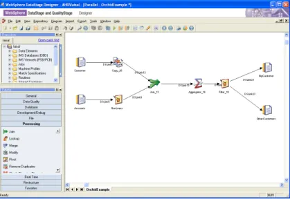
![Figure 2.12: Orchid components and representation layers [DHW + 08]](https://thumb-us.123doks.com/thumbv2/123dok_us/10223927.2926258/55.629.77.499.86.316/figure-orchid-components-representation-layers-dhw.webp)