User Manual: RENESAS Flash Programmer
1 www.ngxtechnologies.com
RENESAS FLASH PROGRAMMER
Flash memory programming software
User’s Manual
Hex Files for BB-RL78/G13_20pin: Click here. Hex Files for BB-RL78/G12_30pin: Click here. Hex Files for BB-RL78/G13_30pin: Click here. Hex Files for BB-RL78/G14_30pin: Click here. Hex Files for BB-RL78/G13_64pin: Click here. Hex Files for BB-RL78/G14_64pin: Click here. Hex Files for BB-RL78/G13_100pin: Click here. Hex Files for BB-RX62N_100pin: Click here.
User Manual: RENESAS Flash Programmer
2 www.ngxtechnologies.com
About NGX Technologies
NGX Technologies is a leader in embedded microcontroller product development. We supply reference designs and evaluation modules to silicon companies. Our customers include industry leaders like NXP and RENESAS. Our core business is in helping our customers realize their embedded products.
Contact Information:
NGX Technologies Pvt. Ltd.
No.216, 5th main Road, R.P.C. Layout, Vijayanagar 2nd Stage,
Bangalore – 560 104 Phone : +91-80-40925507
User Manual: RENESAS Flash Programmer
3 www.ngxtechnologies.comTable of Contents
1.0 INTRODUCTION ... 4 1.1 Features ... 4 1.2 Writing Quality ... 4 1.3 Supported Microcontrollers ... 4 1.4 Operating Environment ... 4 1.4.1 Hardware environment ... 5 1.4.2 Software environment ... 5 2.0 INSTALLATION ... 5 2.1 Obtaining ... 5 2.2 Installation ... 6 2.3 Uninstallation ... 72.4 Updating RFP and Firmware ... 7
3.0 BASIC OPERATION - RL78 ... 8
(1) Installation ... 8
(2) System connection ... 8
(3) Connection of target system ... 8
(4) Creation of workspace ... 9
(5) Selection of program file ... 12
(6) Execute the [Autoprocedure (E.P)] command ... 13
(7) System shutdown ... 14
4.0 BASIC OPERATION - RX ... 15
(1) Installation ... 15
(2) System connection ... 15
(3) Connection of target system ... 15
(4) Creation of workspace ... 16
(5) Selection of program file ... 22
(6) Execute the [Program] command ... 23
(7) System shutdown ... 24
5.0 TROUBLESHOOTING ... 25
5.1 Problems During Startup ... 25
5.2 Problems During Operation ... 26
6.0 CHANGE HISTORY ... 28
6.1 Change History ... 28
User Manual: RENESAS Flash Programmer
4 www.ngxtechnologies.com
1.0
INTRODUCTION
Renesas Flash Programmer (known hereafter as RFP) is software that erases, writes, and verifies programs on the target system or program adapter on which a Renesas Electronics single-chip microcontroller with on-chip flash memory is mounted by using an E1 emulator (E1), E20 emulator (E20), or the on-chip debug emulator with programming function,QB-MINI2 (known hereafter as MINICUBE2), or a serial interface.
Note: We have verified using E1 emulator.
1.1 Features
• Writing controlled by the host machine
• Graphical user interface (GUI) specific to writing • Writing settings can be saved in a workspace file
• Microcontroller-specific information required for writing is included in the product package as a device information file
1.2 Writing Quality
Thoroughly confirm, verify and evaluate the following points before using RFP, in order to improve the writing quality.
• Design circuits as described in the user’s manual for the target microcontroller, E1, E20, and MINICUBE2.
• Use the microcontroller and RFP as described in the user’s manual of the target microcontroller, RFP, E1, E20, and MINICUBE2.
• Make sure that the power supplied to the target microcontroller is stable.
1.3 Supported Microcontrollers
Microcontrollers supported by RFP are listed on the following websites: • Japanese: http://japan.renesas.com/rfp
• English: http://www.renesas.com/rfp
1.4 Operating Environment
This section explains the following items with respect to the operating environment: • Hardware environment
User Manual: RENESAS Flash Programmer
5 www.ngxtechnologies.com1.4.1 Hardware environment
(1) Host machine • PC/ATTM compatible• Processor: 1 GHz or higher (RFP can be used with hyperthreaded and dual core CPUs)
• Main memory: 1 GB or more (2 GB or more when using 64-bit Windows 7®); 2 GB or more recommended
• Display: Resolution of 1,024 x 768 or higher and 65,536 or more colors • Interface: USB 2.0 (when using E1, E20, MINICUBE2, USB Direct) (2) Tools used • E1 • E20 • MINICUBE2
1.4.2 Software environment
• Windows XP®(32-bit only)
• Windows Vista® (32-bit and 64-bit) • Windows 7®(32-bit and 64-bit)
• Microsoft .NET Framework 3.5 SP1 + Language pack
• Microsoft Visual C++ 2008 SP1 Redistributable Package (x86) • Internet Explorer 6.0 or later
2.0
INSTALLATION
The Renesas Flash programmer bundled with the CubeSuite+ software package, while installing CubeSuite+ it is also installs Renesas Flash Programmer.
If not installed with CubeSuite+, follow the below section. This section describes the following items:
• Obtaining • Installation • Uninstallation
• Updating RFP and firmware
2.1 Obtaining
Download the product package (RFP, USB driver, device information file, and utility) from the following websites:
Japanese: http://japan.renesas.com/rfp English: http://www.renesas.com/rfp
User Manual: RENESAS Flash Programmer
6 www.ngxtechnologies.com
2.2 Installation
To install the product package (RFP, USB driver, device information file, and utility), run the bundled executable file
(Renesas_Flash_Programmer_Package_Vxxxxx.exe).Install as instructed by the installer program. After the product package is installed, the folders are organized as follows:
C:\
|---- \Program Files
|----\Renesas Electronics |----\Programming Tools
|---\Renesas Flash Programmer V1.03 |----\CubeSuite+
|---\E-SeriesUSB
2.2.1 Notes on installation
(1) Multiple versions of RFP can be installed on a single host machine. Although we recommend using the latest version of any development tool, leaving a previous version on your host machine and then installing the latest version lets you easily switch the development environment.
(2) You might be asked to reboot your computer after installing the RFP . Be sure to close all other applications before rebooting your computer. (3) You must have administrator privileges to install the RFP.
(4) The RFP can only be installed in a folder that is named using ASCII characters. (Note that the 1 1 characters / * : < > ? | " \ ; , and character strings that begin and end with a space cannot be used.) The RFP might not operate correctly if installed in a folder that is named using other characters.
(5) The RFP cannot be installed from a network drive or on a network drive.
(6) The installer does not specify environment variable paths. If these paths are required, add them after installation.
(7) For the programming GUI installer, the .NET Framework 3.5 SP1 and Visual C++ 2008 SP1 runtime library must be installed in advance. If they are not installed yet, install them in advance.
Installing NET Framework (not required for Windows 7) Microsoft .NET Framework 3.5 Service Pack1 http://www.microsoft.com/downloads/en/details.aspx?displaylang=en&FamilyId=AB99342F-5D1A-413D-8319-81DA479AB0D7
Installing Visual C++ 2008 SP1 Redistributable Package (x86) Microsoft Visual C++ 2008 SP1 Redistributable Package (x86)
http://www.microsoft.com/downloads/en/details.aspx?FamilyID=A5C84275-3B97-4AB7-A40D-3802B2AF5FC2
* If multibyte characters are contained in Windows temporary file names, an error may occur during installation (e.g. the login name is in Japanese).
(8) The following folders created after installation (including the files under the folders) contain files required for the tools to operate. Do not delete them.
User Manual: RENESAS Flash Programmer
7 www.ngxtechnologies.com (Windows is the 32-bit edition and the system drive is C:)
C:\Program Files\Common Files\Renesas Electronics CubeSuite+\ (Windows is the 64-bit edition and the system drive is C:)
C:\Program Files\Common Files (x86)\Renesas Electronics CubeSuite+\
(9) To change the folder of the installed tools, uninstall all the CubeSuite+ related software and the programming GUI for RFP, and install them again.
(10) In the environment where the CubeSuite+, RFP, E1, E20, MINICUBE2 and USB driver for USB Boot are installed the RFP, E1, E20, MINICUBE2 and USB driver for USB Boot are included in the target software of the CubeSuite+ integrated uninstaller. If you don’t want to delete them, remove them from the uninstallation targets.
2.3 Uninstallation
To uninstall the RFP package (RFP, USB driver, device information file, and utility), use “Add or Remove Programs”(or “Programs and Features”) on the Control Panel. The CubeSuite+ integrated uninstaller can also be used to uninstall the RFP package.
2.4 Updating RFP and Firmware
The firmware is a program embedded in the microcontroller for controlling E1, E20, or MINICUBE2. Updating RFP and the firmware enables the following:
• Addition of newly supported functions or microcontrollers • Correction of restrictions
For RFP and the firmware, use of the latest version is recommended to ensure correct operation of E1, E20, and MINICUBE2.
The latest version of the firmware for RFP and MINICUBE2 can be checked and obtained at the following websites:
Japanese: http://japan.renesas.com/rfp English: http://www.renesas.com/rfp
How to check the firmware version and configure and update your system are described below.
For E1 and E20, check that RFP has the correct E1 and E20 firmware versions. If the firmware does not match, the [Renesas Flash Programmer] dialog box will open. Click the Yes button to update.
Figure 2-1. Updating Firmware
For MINICUBE2, see MINICUBE2 Diagnostic Tools User’s Manual (U18588E) for how to check the firmware version,and configure and update your system.
User Manual: RENESAS Flash Programmer
8 www.ngxtechnologies.com
3.0 BASIC OPERATION - RL78
This section describes the operation method by using the RL78/G12 as the target microcontroller as an example to help you understand a series of basic operations with the RFP for the RL78.This section covers how to start the system, execute the [Autoprocedure (E.P)] command, and write the target microcontroller.
• Series of operations described in this section: The operating conditions are as follows:
Target microcontroller: R5F1026A (RL78/G12 20 pin) Target system: NGX’s Blueboard-RL78G12_20pin Tool used: E1
Communication port: UART-ch0
Communication speed setting: 1,000,000 bps
Clock setting: None (internal oscillation clock used) Power settings: Programmer (5.0 V)
Operating mode: Chip Flash option: Not used
Operation option: [Blank Check before Erase] enabled The steps described in this chapter are as follows: (1) Installation
(2) System connection
(3) Connection of target system (4) Creation of workspace (5) Selection of program file
(6) Execution of [Autoprocedure (E.P)] command (7) System shutdown
(1) Installation
See section INSTALLATION and install in the host machine.
(2) System connection
Connect the USB connector of RFP to the USB port on the host machine using a USB cable.
(3) Connection of target system
Connect the target cable of the tool used to the target system.
Remark
User Manual: RENESAS Flash Programmer
9 www.ngxtechnologies.com
(4) Creation of workspace
Step 1: On the taskbar, click the Start button, point to [All Programs], [Renesas Electronics
CubeSuite+], [Programming Tools], [Renesas Flash Programmer Vx.xx], and then click [Renesas Flash Programmer Vx.xx [Basic mode]]. The [Welcome!] dialog box will open. Select [Create new
workspace.] and then click the Next button to open the [Create a new workspace] dialog box.
Figure 3-1 [Welcome!] Dialog Box
Step 2: In the [Using Target Microcontroller:] list box, select “R5F1026A”. Enter any text string (such as “sample” in this case) in the [Workspace Name:] box, and specify any folder in the [Folder:] box. Clicking the Next button displays the [Select Communication Interface] dialog box.
Figure 3-2. [Create a new workspace] Dialog Box Note: Select the same name as that of the target microcontroller.
User Manual: RENESAS Flash Programmer
10 www.ngxtechnologies.com
Step 3: Select “E1” in the [Select Communication Interface] dialog box. For R5F1026A, the selection in the [Select Interface:] list box is fixed to “UART-ch0”.
Clicking the Next button displays the [Setting Oscillator] dialog box.
Figure 3-3. [Select Communication Interface] Dialog Box
Step 4: Select “1,000,000bps” from the [Interface Speed:] list box. For R5F1026A, the [Supply Oscillator] area is fixed to “Internal-OSC”.
Clicking the Next button displays the [Setting Power Supply] dialog box in the case of E1.
User Manual: RENESAS Flash Programmer
11 www.ngxtechnologies.com
Step 5: Select the [Power target from the emulator] check box, and then select “5.0V” for [Supply voltage].
Clicking the Next button displays the [Information Settings] dialog box.
Figure 3-5. [Setting Power Supply] Dialog Box
Step 6: “Chip” is the default value for [Operation mode] under the [Target] category, and the default value for “Blank Check before Erase” in the [Command Options] category is “Valid”.
Clicking the Complete button saves the project file and displays the main window.
User Manual: RENESAS Flash Programmer
12 www.ngxtechnologies.com
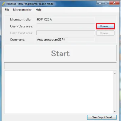
(5) Selection of program file
Step 1: Click the Browse… button in “User/Data area:” of the program file area to open the [Open File] dialog box.
Figure 3-7. Main Window
Step 2: Select “BB-RL78G12pin_LED_blinky.hex” in the [Open File] dialog box, and then click the Open button to open the main window.
User Manual: RENESAS Flash Programmer
13 www.ngxtechnologies.com
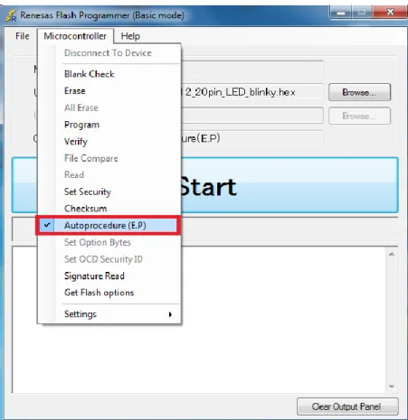
(6) Execute the [Autoprocedure (E.P)] command
Step 1: Click the [Microcontroller] menu and select the [Autoprocedure (E.P)] command. A check mark is then placed on the left of the command, and the command is assigned to the Start button.
Figure 3-9. Main Window .
Step 2: After clicking the Start button, execute the following commands in the following order for R5F1026A: [Blank Check] command, [Erase] command (if there are no blanks), and [Program] command.
Remarks
1. When necessary, insert the target microcontroller (microcontroller to be programmed) into the program adapter, then execute the [Autoprocedure (E.P)] command.
2. When supplying VDD power to the target system, first turn off the power, connect the target system (for programming), and then turn on the power and execute the [Autoprocedure (E.P)] command. Step 3: When execution of the [Autoprocedure (E.P)] command ends normally, "--End
(Autoprocedure(E.P)) ---"is displayed on the output panel.
User Manual: RENESAS Flash Programmer
14 www.ngxtechnologies.com
Figure 3-10. [Autoprocedure (E.P)] Command Execution Results
(7) System shutdown
Step 1: Disconnect the target cable from the target system.
Remark When supplying VDD power to the target system, turn off the power before removing the target cable.
Step 2: Unless there are other target microcontrollers to be programmed, click the [File] menu and select the [Exit] command to close RFP. Because all settings made so far will be saved to a project file, they can be reused after RFP is restarted.
Step 3: Remove the USB cable from the tool used.
Step 4: Connect the external power supply to the target board then the USER LED(D1) should blink. Caution:
If an error occurs during the above procedure, see section 5 TROUBLESHOOTING. Also see the user’s manual of the tool used and execute diagnostic tests.
User Manual: RENESAS Flash Programmer
15 www.ngxtechnologies.com
4.0 BASIC OPERATION - RX
This chapter describes the operation method by using the RX as the target microcontroller as an example to help you understand a series of basic operations with the RFP for the RX. This chapter covers how to start the system, execute the [Program] command, and write the target microcontroller.
• Series of operations described in this section: The operating conditions are as follows: Target microcontroller: R5F562N8B (RX62N) Target system: NGX’s Blueboard-RX62N_100pin Tool used: E1
Connection mode: Boot mode
Communication speed setting: 1,562,500 bps
Clock setting: 12.50 MHz (main clock × 8 multiplication, peripheral clock × 4 multiplication) Power settings: Programmer (5.0 V)
Lock bit: None
Other settings: Initial value
The steps described in this section are as follows: (1) Installation
(2) System connection
(3) Connection of target system (4) Creation of workspace (5) Selection of program file
(6) Execution of [Program] command (7) System shutdown
(1) Installation
See section 2 INSTALLATION and install in the host machine.
(2) System connection
Connect the USB connector of RFP to the USB port on the host machine using a USB cable.
(3) Connection of target system
Connect the target cable of the tool used to the target system.
User Manual: RENESAS Flash Programmer
16 www.ngxtechnologies.com
(4) Creation of workspace
Step 1: On the taskbar, click the Start button, point to [All Programs], [Renesas ElectronicsCubeSuite+], [Programming Tools], [Renesas Flash Programmer Vx.xx], and then click [Renesas Flash Programmer Vx.xx [Basic mode]]. The [Welcome!] dialog box will open. Select [Create new workspace.] and then click the Next button to open the [Create a new workspace] dialog box.
Figure 4-1. [Welcome!] Dialog Box
Step 2: In the [Using Target Microcontroller:] list box, select “Generic Boot Device”. Enter any text string (such as “sample” in this case) in the [Workspace Name:] box, and specify any folder in the [Folder:] box.
Clicking the Next button displays the [Select Communication Interface] dialog box.
User Manual: RENESAS Flash Programmer
17 www.ngxtechnologies.com
Step 3: Select “E1” in the [Select Tool:] list box. For R5F562N8B, the selection in the [Select] list box is fixed to “Bootmode”.
Clicking the Next > button displays the [Setting Power Supply] dialog box.
Figure 4-3. [Select Communication] Dialog Box
Step 4: Select the [Power target from the emulator] check box, and then select “5.0 V” for [Supply voltage].
Clicking the OK button displays the [Mode Pin Settings at Connection] dialog box.
Figure 4-4. [Setting Power Supply] Dialog Box
Step 5: Set the [Pin Outputs] check boxes and [Pin Setting (High)] check boxes. For R5F562N8B, set io2 of E1 to High for the MD0 pin, and set io3 of E1 to Low for the MD1 pin.
User Manual: RENESAS Flash Programmer
18 www.ngxtechnologies.com
Figure 4-5. [Mode Pin Settings at Connection] Dialog Box
Step 6: Check that the board is connected, powered, and in Boot mode. Clicking the OK button displays the [Select Emulator] dialog box.
Figure 4-6. [Confirmation Before Connection] Dialog Box
Step 7: The name and serial number of the detected Emulator are displayed.Select it.
Clicking the OK button establish connection with the device and displays the [Query Generic Device] dialog box.
User Manual: RENESAS Flash Programmer
19 www.ngxtechnologies.com Step 8: A query for the target microcontroller is performed. Clicking the OK button displays the [Setting Clock] dialog box.
Figure 4-8. [Query Generic Device] Dialog Box
Step 9: Enter “12.50” in the [Input Frequency:] box in the [Clock supply] area. The [Internal/External:] list box displays the result of the query “External Resonator or Clock.” Select “8” from the [CKM:] list box in the [Multiplier for the main clock or peripheral clock] area. Select “4” from the [CKP:] list box. The [Clock Mode:] list box displays the result of the query “0”.
Clicking the Next > button displays the [Setting Baudrate] dialog box.
User Manual: RENESAS Flash Programmer
20 www.ngxtechnologies.com
Step 10: Clear the [Use Default] check box, and select “1562500” from the [Recommended Speeds:] list box. Clicking the Finish button displays the [List of Settings] dialog box.
Figure 4-10. [Setting Baudrate] Dialog Box
Step 11: The [Basic Settings] tab in the [List of Settings] dialog box allows you to check basic information about programming. Clicking the [Other Settings] tab of the [List of Settings] dialog box displays the [Other Settings] tab in the [List of Settings] dialog box.
User Manual: RENESAS Flash Programmer
21 www.ngxtechnologies.com
Step 12: The [Other Settings] tab in the [List of Settings] dialog box allows you to specify and check advanced information about programming. For [Connect Option] and [Disconnect Option] in the [Lock Bit] category, select “Do Nothing.” Leave the initial values for other settings.
Clicking the OK button saves the project file and displays the main window.
User Manual: RENESAS Flash Programmer
22 www.ngxtechnologies.com
(5) Selection of program file
Step 1: Clicking the Browse… button in the User/Data area: of the program file area displays the [Open File] dialog box.
Figure 4-13. Main Window
Step 2: Select “NGX_RX62N_100pin_blinky.hex” in the [Open File] dialog box, and then click the Open button to open the main window.
User Manual: RENESAS Flash Programmer
23 www.ngxtechnologies.com
(6) Execute the [Program] command
Step 1: Click the [Microcontroller] menu and select the [Program] command. A check mark is then placed on the left of the command, and the command is assigned to the Start button.
Figure 4-15. Main Window
Step 2: After clicking the Start button, execute the [Program] command for R5F562N8B.
Remarks
1. When necessary, insert the target microcontroller (microcontroller to be programmed) into the program adapter, then execute the [Program] command.
2. When supplying VDD power to the target system, first turn off the power, connect the target system (for programming), and then turn on the power and execute the [Program] command.
3. When the [Program] command is executed, programming is performed after the block with data is Erased. To erase all blocks, set [All Erase Before Program] in the [Flash Program Options] category in the [Other Settings] tab of the [List of Settings] dialog box to “True.”
User Manual: RENESAS Flash Programmer
24 www.ngxtechnologies.com
Step 3: When execution of the [Program] command ends normally, “Image written to device” and “Disconnected” are displayed on the output panel.
Figure 4-16. [Program] Command Execution Results
(7) System shutdown
Step 1: Disconnect the target cable from the target system.
Remark
When supplying VDD power to the target system, turn off the power before removing the target cable. Furthermore, if [Auto Disconnect] in the [Flash Program Options] category in the [Other Settings] tab of the [List of Settings] dialog box is set to “False,” remove the target system after Executing [Disconnect To Device].
Step 2: Unless there are other target microcontrollers to be programmed, click the [File] menu and select the [Exit] command to close RFP. Because all settings made so far will be saved to a project file, they can be reused after RFP is restarted.
Step 3: Remove the USB cable from the tool used.
Step 4: To execute the user code supply power using USB cable to the target board and set Boot switch to 1100 then LED (D2) should blink.
Caution:
If an error occurs during the above procedure, see section TROUBLESHOOTING. Also see the user’s manual of the tool used and execute diagnostic tests.
User Manual: RENESAS Flash Programmer
25 www.ngxtechnologies.com
5.0 TROUBLESHOOTING
This section explains how to troubleshoot RFP. Remark
Using the diagnostic tool, the user can find out why RFP does not run normally, such as due to a defect in the tool used, or problems in other hardware. For how to use the diagnostic tool, see the user’s manual of the tool used.
5.1 Problems During Startup
This section explains how to troubleshoot problems that might occur in the process from installation to startup.
(1) When the tool is connected to the host machine via a USB interface, the driver is not recognized by Plug and Play.
Cause:
The USB connector might not be inserted properly into the USB port of the host machine. Action:
Check that the USB connector is fully inserted into the USB port of the host machine. Alternatively, disconnect the USB connector, and then insert the USB connector again after a while.
(2) The USB driver file cannot be found at the specified location. Cause:
The USB driver might not have been installed normally. Action:
See section 2 RFP INSTALLATION and reinstall the USB driver.
(3) The tool is connected to the host machine but the power LED on the tool is not turned on. Cause:
The USB port of the tool or the host machine might have a defect.
Action:
Check a defect of the tool using the diagnostic tool for the tool used. If a defect is found, consider repair. Ifthere is no defect, try connecting the tool to another machine.
(4) The “Add New Hardware Wizard” screen appears when tool is connected with the host machine.
Cause:
If the USB connector of the tool is inserted into a port that differs from the one used during installation, the tool might be recognized as a new hardware item.
Action:
User Manual: RENESAS Flash Programmer
26 www.ngxtechnologies.com
5.2 Problems During Operation
This section describes the troubleshooting for problems that may occur during operation. (1) One of the following errors is displayed on the output panel.
Error (E1000001) : E1/E20/MINICUBE2/COMx communication time out. Error (E1000009) : E1/E20/MINICUBE2/COMx
Cause 1:
The USB cable might not be connected properly or the USB driver might not have been installed normally.
Action 1:
See 5.1 Problems During Startup and take an appropriate action. Cause 2:
The installed USB driver is not displayed in the Device Manager. Alternatively, the “!” or “×” is prefixed.
Action 2:
<1> With RFP connected to the host machine, right-click the driver marked with the “!” or “×”, and then click [Uninstall].
<2> Execute [Scan for hardware changes] in the Device Manager. <3> Reinstall the USB driver by Plug and Play.
Cause 3:
The tool might not have been recognized (when connected via a USB hub). Action 3:
Try the following:
<1> Disconnect the USB cable and then reconnect it.
<2> Connect the USB connector to another port on the USB hub.
<3> If the above measures do not resolve the problem, do not use the USB hub but directly connect the USB connector to the USB port of the host machine main unit.
(2) The following message is displayed in the output panel and the flash memory programming mode cannot be entered.
Error (E1002001): No response from Target Microcontroller (FLMD). Error (E1002002): No response from Target Microcontroller (RESET). Error (E1002003): No response from Target Microcontroller (FREQ). Cause 1:
The wrong microcontroller name might be selected in the [Create a new workspace] dialog box. Action 1:
Select the same name as that of the target microcontroller. Cause 2:
No clock might be able to be supplied to the target microcontroller. Action 2:
User Manual: RENESAS Flash Programmer
27 www.ngxtechnologies.com
<1> Check if the settings in the [Supply Oscillator] dialogbox are correct. For the correct settings, see theuser’s manual of the target microcontroller.
<2> Check the clock supply on the target system.
Cause 3:
Power might not be supplied normally to the target microcontroller. Action 3:
<1> Check the power supply setting.
<2> Check that the power is supplied on the target system. If the power is supplied from the tool used, a power shortage might occur. In such a case, supply power from the target system.
Cause 4:
For the RX, the I/O signal setting does not match the wiring of the target system. Action 4:
Check if the settings in the [Mode Pin Settings] dialog match the wiring of the target system. (3) The following message is displayed on the output panel and normal communication is not performed inthe flash memory programming mode.
Error (E1002004): Communication failure or timeout.
Cause 1:
The clock or power supply might not be stable.
Action 1:
Confirm that the clock or power is stably supplied on the target system. Cause 2:
Communication might not be stable. Action 2:
<1> Check that there is no noise on the communication line.
<2> Confirm that the tool used is properly connected with the target system. <3> Confirm that unused pins are properly handled.
<4> Confirm that the correct clock and communication rate are selected. Stable programming might be achieved by setting a lower value for the clock or communication rate.
User Manual: RENESAS Flash Programmer
28 www.ngxtechnologies.com6.0
CHANGE HISTORY
6.1 Change History
7.0 REFERENCES
RENESAS Flash Programmer 1.0x User’s manual:
http://documentation.renesas.com/doc/products/tool/doc/r20ut0599ej0400_rfp.pdf Additional references include:
Information on development tool and Emulator being used:
CubeSuite+, http://sg.renesas.com/products/tools/ide/ide_cubesuite_plus/
E1 Emulator: http://sg.renesas.com/products/tools/emulation_debugging/ onchip_debuggers/e1/index.jsp
About this document:
Revision History
Version: V1.0 author: Veeresh Tumbaragi Company Terms & Conditions
Legal
NGX Technologies Pvt. Ltd. provides the enclosed product(s) under the following conditions:
This evaluation board/kit is intended for use for ENGINEERING DEVELOPMENT, DEMONSTRATION, and EDUCATION OR EVALUATION PURPOSES ONLY and is not considered by NGX Technologies Pvt. Ltd to be a finished end-product fit for general consumer use. Persons handling the product(s) must have electronics training and observe good engineering practice standards. As such, the goods being provided are not intended to be complete in terms of required design-, marketing-, and/or manufacturing-related protective considerations, including product safety and environmental measures typically found in end products that incorporate such semiconductor components or circuit boards. This evaluation board/kit does not fall within the scope of the European Union directives regarding electromagnetic compatibility, restricted substances (RoHS), recycling (WEEE), FCC, CE or UL and therefore may not meet the technical requirements of these directives or other related directives.
The user assumes all responsibility and liability for proper and safe handling of the goods. Further, the user indemnifies NGX Technologies from all claims arising from the handling or use of the goods. Due
Rev Changes Date (dd/mm/yy) By
1.0 Initial release of the User Manual 04/10/2012 Veeresh Tumbaragi
User Manual: RENESAS Flash Programmer
29 www.ngxtechnologies.com
to the open construction of the product, it is the user’s responsibility to take any and all appropriate precautions with regard to electrostatic discharge.
EXCEPT TO THE EXTENT OF THE INDEMNITY SET FORTH ABOVE, NEITHER PARTY SHALL BE LIABLE TO THE OTHER FOR ANY INDIRECT, SPECIAL, INCIDENTAL, OR CONSEQUENTIAL DAMAGES.
NGX Technologies currently deals with a variety of customers for products, and therefore our arrangement with the user is not exclusive. NGX Technologies assumes no liability for applications assistance, customer product design, software performance, or infringement of patents or services described herein.
Please read the User’s Guide and, specifically, the Warnings and Restrictions notice in the User’s Guide prior to handling the product. This notice contains important safety information about temperatures and voltages.
No license is granted under any patent right or other intellectual property right of NGX Technologies covering or relating to any machine, process, or combination in which such NGX Technologies products or services might be or are used.
Disclaimers
Information in this document is believed to be reliable and accurate. However, NGX Technologies does not give any representations or warranties, expressed or implied, as to the completeness or accuracy of such information and shall have no liability for the consequences of use of such information.
NGX Technologies reserves the right to make changes to information published in this document, at any time and without notice, including without limitation specifications and product descriptions. This document replaces and supersedes all information supplied prior to the publication hereof.
Trademarks
All referenced trademarks, product names, brands and service names are the property of their respective owners.
![Figure 3-2. [Create a new workspace] Dialog Box Note: Select the same name as that of the target microcontroller](https://thumb-us.123doks.com/thumbv2/123dok_us/10240398.2928389/9.892.258.644.655.1022/figure-create-workspace-dialog-note-select-target-microcontroller.webp)
![Figure 3-3. [Select Communication Interface] Dialog Box](https://thumb-us.123doks.com/thumbv2/123dok_us/10240398.2928389/10.892.178.725.177.483/figure-select-communication-interface-dialog-box.webp)
![Figure 3-6. [Information Settings] Dialog Box](https://thumb-us.123doks.com/thumbv2/123dok_us/10240398.2928389/11.892.193.707.675.1084/figure-information-settings-dialog-box.webp)
![Figure 3-10. [Autoprocedure (E.P)] Command Execution Results](https://thumb-us.123doks.com/thumbv2/123dok_us/10240398.2928389/14.892.208.699.109.603/figure-autoprocedure-command-execution-results.webp)
![Figure 4-2. [Create a new workspace] Dialog Box](https://thumb-us.123doks.com/thumbv2/123dok_us/10240398.2928389/16.892.245.663.692.1100/figure-create-new-workspace-dialog-box.webp)
![Figure 4-3. [Select Communication] Dialog Box](https://thumb-us.123doks.com/thumbv2/123dok_us/10240398.2928389/17.892.190.717.216.574/figure-select-communication-dialog-box.webp)
![Figure 4-5. [Mode Pin Settings at Connection] Dialog Box](https://thumb-us.123doks.com/thumbv2/123dok_us/10240398.2928389/18.892.197.712.135.384/figure-mode-pin-settings-at-connection-dialog-box.webp)
![Figure 4-8. [Query Generic Device] Dialog Box](https://thumb-us.123doks.com/thumbv2/123dok_us/10240398.2928389/19.892.455.766.193.407/figure-query-generic-device-dialog-box.webp)
