Effect of Interaction of Wave and Forward Speed
on Hydrodynamic Forces on Marine Structures
Makoto Ohkusu
Research Institute for Applied Mechanics, Kyushu University, Kasuga, Japan
ABSTRACT
First an overview is given of researches on the prediction methods of hydrodynamic forces on a body moving in waves at a steady forward speed. Then two methods developed by the author are presented, and their results are discussed. These two methods are based on different assumptions of the steady flow field around the body.
OVERVIEW
The prediction of hydrodynamic forces on offshore structures in a current as well as in waves, or towed at a steady speed in waves, must be based on a correct understanding of the hydrodynamic in-teraction effect of the structures' steady forward speed and waves. There are other less obvious contexts in which this effect must be considered: Slow drift oscillation in waves is of such a large am-plitude and long period compared with wave motions that it may be considered as a quasi-steady movement in waves. Damping of the slow drift oscillation may be predicted from a steady force when assuming that structures move at a steady speed in waves backward or forward. Tilt moment on the structures in waves is caused by steady wave forces acting in the vertical direction. The steady wave forces are necessarily affected by the steady speed of the structures. That means the tilt moment is also to be predicted taking into consideration that the structures are doing slow drift oscillation in waves.
This overview gives a brief review of recent theoretical re-searches on the prediction of hydrodynamic forces on bodies moving at constant speed in waves. Description is restricted to the theories.
The correct prediction of hydrodynamic forces on a floating body moving at steady velocity in waves has been mainly a con-cern of ship hydrodynamicists. In the context of seakeeping of ship, its geometrical form is often assumed very slender. The pre-diction of those forces on bluff bodies such as offshore structures is quite a different problem.
In order to remove the limitation of approach of ship hydrody-namics, three-dimensional panel methods at non-zero forward speed were proposed by Chang (1977); Kobayashi (1981); Inglis and Price (1981); and Guevel and Bougis (1982). In these meth-ods, body surface is divided into a number of panels on which strength of source or dipole is assumed constant; velocity poten-tial is expressed by the Green function satisfying a linear free sur-face condition incorporating the uniform and steady ambient flow equivalent to the steady movement of a body; strength of dipole or source is determined such that the normal velocity of fluid is pre-scribed on the body surface with forced motions of the body for radiation problem or incident waves for diffraction problem. Received May 1, 1990: revised manuscript received by the editors January
22, 1991.
KEY WORDS: Waves, bodies at forward speed, wave and current inter-action.
No geometrical restriction is explicitly assumed on body forms in this computation. However, we note that this approach is math-ematically inconsistent in that no interaction with stationary flow due to forward speed is considered in the free surface condition: The interaction can be assumed to be of a higher order of magni-tude and ignored if, and only if, the body form is slender.
These boundary integral equation methods in frequency do-main, though based on an inconsistent assumption, are expected to generally improve our understanding of the effect of the steady speed of offshore structures or current on the wave forces. The computations referred to above, however, employed 200 as the greatest number of panels - probably because their computa-tional schemes of the Green function were not fast enough on computers available at that time. It may be concluded that the ac-curacy of their results is not sufficiently validated, considering that about 12,000 panels are required for the successful validation of the results at zero steady speed achieved by Korsemeyer et al. (1988). They confirmed convergence of the results with the in-crease in the number of panels.
Difficulties associated with the computation at non-zero steady speed are: Much computer time is required to obtain the accurate value of the Green function; lack of confidence in the accuracy of the solutions, generally caused by a line singularity on the inter-section of the body and free surface.
For results of the panel method at non-zero forward speed to be validated with the same level of confidence as at zero forward speed, further investigations are required. Ohkusu and Iwashita (1989) reported some progress in this direction. They presented the results of a convergence test by a panel method based on a new and fast scheme for evaluating the Green function which fa-cilitated a large number of panels - close to 1000 - with practi-cally feasible computer time. It is concluded that convergence is satisfactory with such a large number of panels on submerged spheroids. A few more details and more recent results of their re-search are described below.
Uniform and steady ambient flow is not a correct substitute for the effect of steady forward speed of a body on hydrodynamic forces in waves. This is recognized in terms of the incorrect pre-diction of added resistance to waves, in particular, of a blunt-bow hull form. The author found that added resistance derived from measured wave energy away from a ship model is substantially smaller than that measured by a force gauge. This might be inter-preted as follows: Some part of the energy of diffraction waves cannot reach to the far field in the form of waves because of their
UNIFORM FLOW PROBLEM
Far away from the cylinder, Eq. 1 will become:
In this section we present some details of a boundary integral method to solve a boundary value problem for the unsteady flow around a body moving into waves at forward speed when we as-sume the effect of forward speed is uniform in the free surface con-dition; we employ the following free surface condition on z=0
(3) (2)
(~at _ U
~)2
ax <j>+
ga<j>az =0which is identical to the ordinary linear free surface condition as-suming uniform flow U provided the terms of higher order than
O(U) are excluded.
This approach is plausible because the approximation may fit in well with what we observed in the experiment as shown in Fig. 1 and U(x,z) in the free surface condition is quite consistently re-placed by a solution for the steady flow around the body with a rigid wall free surface condition. This solution is obtained quite easily and with no ambiguity. Moreover the analytical difficulty at the intersection of the body and the free surface appears to be re-duced by the introduction of the non-uniformity of the U.
The method of solving this problem even when including the terms of order O(U2) in the free surface condition is presented be-low, and the results are discussed.
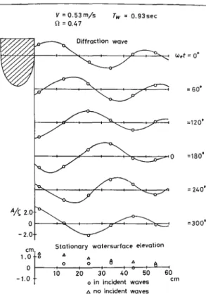
modification and/or breaking on the non-uniform flow field in the vicinity of the blunt bow. This possibility was demonstrated in a simple experiment by Ohkusu (1984). A horizontal cylinder was towed at speed U in regular incident waves with encounter fre-quency IDein a direction at right angle to its axis with its motion suppressed. The length of the cylinder selected was almost identi-cal with the width of the model basin; the flow field around the cylinder is regarded as two-dimensional (2D). Assuming the rela-tive ambient flow is uniform
-U,
then the diffraction waves prop-agating forward upstream of the cylinder are not present when the group velocity of the diffraction waves is slower than the flow ve-locity U, that is when UIDe/g is larger than 0.25.Fig. 1 shows a 2D wave pattern measured ahead of the cylinder and drawn in sequence of time elapsed. Components of incident waves are excluded from the data. Obviously diffraction waves propagate upstream even at such a high velocity of U IDe/g=0.47. Actually the relative flow must be non-uniform close to the cylin-der and much slower than the forward speed U; ULIDe/g defined with the local flow velocity UL in the vicinity of the cylinder must be small enough for the waves to propagate upstream even when the nominal U IDe/g >0.25. This experiment suggests that non-uniformity of the steady flow close to the body moving at a con-stant velocity must be considered in the diffraction of waves.
Recently theoretical researches have been attempted to incorpo-rate the effect of non-uniformity of the steady flow around a bluff body into the linearized free surface condition. Zhao et al. (1989) proposed including the non-uniform flow effect of speed U(x,y ,z)
up to the order O(U) in the free surface condition close to the body. The free surface condition close to the cylinder in the 2D case, for instance (as shown in Fig. I), is given by:
where the x-axis is taken into the direction upstream of the cylin-der and the z-axis vertically upward.
a2<j> _ 2U(x,0) a2<j> au(x,o) a<j>+ga<j>
=
0 on z=
0 (1)at2 axat ax at az
Stationary watersurface elevation
A
(5) (4)
f.-It/2+~[k2i'P - sgn( cosS)k1ekIP]
T(x,y,z)=
--~==~-dS
a-It ~1 +41:cosS
rl.2=~(x - x,)2 +(y _ y')2 +(z=+=z,)2 P =z +(xcosS)+ (y sinS)
k1.2 =Ko/2(1 +21:cosS± ~1 +41:cosS )sec2 S
G(x,y,z;x,y,z"') =-41 (11t ---rl r21)
--2
i
1tT(x-x ,,y-y ,,z+z ,)where
The boundary integral method described here uses the Green function satisfying the free surface condition (3) and the radiation condition.
As mentioned above, the CPU time required for evaluating the Green function with the controlled degree of accuracy is the most crucial factor for this method to be available for practical applica-tion. Unless we have a faster scheme, which can afford a large number of panels on the body, the convergence of numerical com-putation with an increase in the number of panels will not be tested. Recently validation of this kind of numerical solution has been required.
The author and his colleague (Ohkusu and Iwashita, 1989, and Iwashita and Ohkusu, 1990) proposed a new scheme to evaluate the Green function with sufficient speed and with the controlled degree of accuracy. In their scheme the Green function
G(x,y,z;x',y',z')eiOlt is written in a single integral form: = 60' =120' 0 =180' = 240' =300' 60 em A Tw = 0.9350e A o o v=0.53 m/5 11=0.47 1.e;,.j.~ o -1.0
where
8 is a complex number dependent on the values ofx,y and z. Integration of Eq. 7 should be done along a curve directing at
m ~ 00 into
( ) z(m-Ko't)2.[ ~(m-Ko't)4 -(Kom)2]
I/J
m
= +1xm-y---Ko Ko (8)
0= k1cos(-n12 +~)
Accuracy Ko(zKo(z++z')z')=-1= _10-3 10-4 0.012sec0.014sec 10-5 0.014sec0.016sec 10-6 0.016sec0.018sec 10-7 0.018sec0.019sec 10-8 0.019sec0.020sec
NON-UNIFORM FLOW PROBLEM
Non-uniform steady flow, which is induced by its steady move-ment around the body, interacts with unsteady flow caused by the body's oscillation and wave motions. This interaction must appear in the free surface condition and the body boundary condition. Table 1 Average CPU time for various depth of source
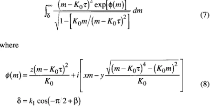
The speed of numerical computation of the Green function is improved extraordinarily by this scheme, although we are not completely satisfied. We carried out several tests on the effective-ness of this scheme, applying it to solving the boundary value problem of a spheroid oscillating and moving at steady speed be-neath the free surface. Figs. 2 and 3 show the results of a conver-gence test of the numerical solution with the increase in the num-ber of panels on the body. Fig. 2 is added mass and Fig. 3 is the damping coefficient of heaving at forward speed Fn= 0.2 and fre-quency ro2/gL = 5.0 drawn vs. I/N where N is the number of pan-els. Two lines in each figure are the results of two slightly differ-ent computational methods to solve boundary value problems. The most left points correspond to about 2,000 panels. Those re-sults show that convergence is consistent with the increase of the number of panels, and that accuracy up to three digits is not guar-anteed if the number of panels is below 2,000.
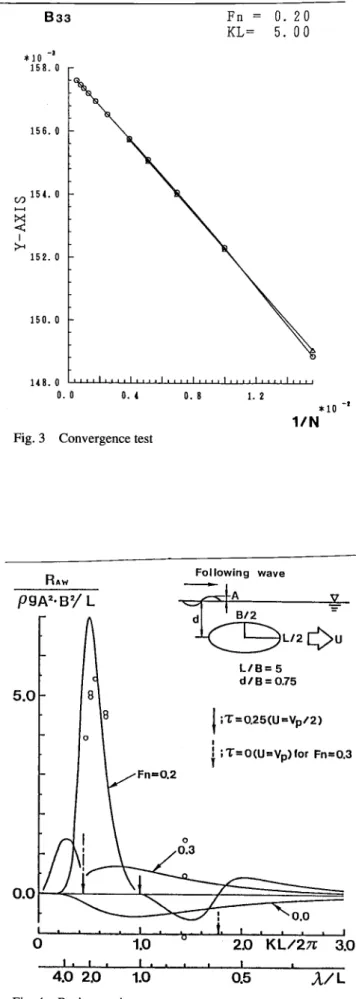
Fig. 4 shows the computed resistance increase exerted on a spheroid moving at steady speed into the same direction as wave propagation but with the oscillatory motions suppressed. One re-markable point in this figure is that the resistance increase is con-siderably larger when the group velocity of the incident waves is higher than the body speed. This was confirmed by a model ex-periment whose results are shown by circle marks. Another re-markable point is that negative resistance increases when the body speed is higher than the group velocity of the waves, that is, when no disturbance propagates forward of the body.
The analytical difficulty intrinsic in the linear problem of a floating body oscillating and running at forward speed in the free surface is a singularity on the intersection of the body and the free surfaces. For instance, strength of source or dipole on this inter-section is an indeterminate when solving the boundary value prob-lems. Assumption of the regularity or the least singularity of the flow very close to the intersection is often employed. Actually we used the expression giving the regularity when we applied the boundary integral equation method described above to the bodies piercing the free surface. But so far we are not confident that this assumption gives a stable numerical solution, let alone a physi-cally correct answer to our problems. This will be the next prob-lem to be solved with this approach.
The average CPU time of FACOM M780/20 required for this scheme to calculate a value of the Green function and its three components of fluid velocity for one combination of source and field points are shown in Table 1 for different degrees of accu-racy, where z and z' are z -coordinate of the field and source points and Ko =g/U2.
(9) (7)
(6)
a
= cos-1(l/4't)~=cos-l(x/~x2+i )-isin-1(lzl
~x2+i)
K2 denotes g/U2 and 't =Uro/g.
Eq. 4 is a single integral expression of the Green function with its integrands of elementary functions; this is somewhat modified from the original given by Bessho (1977). Integration must be done along a curve in the complex plane because
a
given by Eq. 6 is an imaginary number if r is less than 0.25 and f3is a complex number.Numerical integration of the first term of T(x,y,z) is straightfor-ward. Singularity at
e
=a -
7rdoes not cause any serious trouble in numerical integration unless 't is equal to 0.25. Integration of the second term requires special consideration, because the inte-grand oscillates dreadfully and its magnitude increases without limit whene
approaches ±n/2. Introducing a new variable m=k1 cose, we transform the integral of the second term from e =-n/2
+ ~ to-n/2
into:as long as z is negative or y is not zero.
The general idea of the scheme of evaluating the contour inte-gral (7) with less CPU time when the degree of accuracy is speci-fied is as follows:
(I) Find numerically a deformed contour starting from 0 on which the imaginary part of I/J(m)is almost constant and the real part descends the steepest way. This process is achieved by inte-grating the differential equation of the contour step by step. The contour must not cross the branch cuts of I/J(m).When 8 is located left of one of the zeroes of I/J(m),then 9\[l/J(m)] ascends at the be-ginning part of the contour before reaching an appropriate location from which we can find the steepest descent path into direction (9). (2) Integrate Eq. 7 numerically along this deformed contour up to the point beyond which the contribution of the remaining part is less than a specified truncation error limit. Convergence of this in-tegration is so fast and so that CPU time is mostly spent in finding the contour.
(3) When both z and yare very small compared withx, numeri-cal integration of the integral is slower in convergence. In this case a complementary method - more analytical and using com-plementary error function - is introduced to increase the robust-ness and efficiency of the scheme.
The latter was considered in the computation described above. Completely consistent linearization of the free surface condi-tion including both the unsteady and the steady flow effects is not straightforward and not a unique one. One reason is that parame-ters for linearization are quite different for the steady flow field around the body from those for the unsteady flow field: Ampli-tude of oscillatory motion is almost a unique parameter for lin-earization of the unsteady flow, while for linearization of the steady flow we have several alternatives of assumption on the flow variables which are often based on body geometry. Besides, it is a known difficulty to predict correctly the steady flow if it has to be a solution satisfying the free surface condition, even though it is linearized. In this regard, it is rather natural both for theoreti-ca~ convenience and practicality that Zhao et al. (1988) assumed the slow steady speed. This assumption allows us to use a solid wall condition atz=ainstead of the free surface condition (3) for the steady flow.
Kashiwagi and Ohkusu (1988) gave a free surface condition of 2D flow including the effect of the non-uniform steady flow up to the order of0(U2). It is:
where U ¢s and
¢
are velocity potentials of the steady flow and the unsteady flow. This is imposed at z=a
close to the body, while the condition (3) is away from it.They assumed U¢sis the flow satisfying the solid wall condition on the free surface for computational convenience, although this is not consistent with the inclusion of the terms up to0(U2); the re-ally consistent free surface condition with this assumption is Eq. 1.
833
*10 -8 158. 0 156. 0 (/)154.0 I-<~
I >< 152. 0 15 O. 0 14 8. 0 O. 0 O. (Fig. 3 Convergence test
O. 8 Fn= 0.20 KL= 5. 00 1. 2 *10 -I
lIN
A33O. 20 FollowingFnRAw =wave KL= 5. 00
p9N'SYL
dl~ -*1 0-Ir
f\ 57. 0 r L/2c)U --56. 5 ~I ,
l-
~
L/B= 5 dlB = 0.75 56. 0 f-/
5.0~
r\
55. 5f-/
I
;L"=0.25(U=Vpl2) I ~ 55. 0 ~/
tI
;L"=O(U=Vp)lor Fn=0.3l
-
--:>< -<I 54. 5 >< 54. 0 53. 5 53. 0 52. 5r
,,(~l ..•.•0.0~
·u.
t.I
...
52. 0 I ellI III I I •II • I IIItI III I I III I I III I I I IIt I IKL/2n
3.0
to
2.0
0
o.0 O. 4 O. 8 1.2I.
I
I •
*10 -I.
.
1/N
4.0 2.0
1.00.5
A/L
Fig. 2Convergence test Fig. 4
The numerical method to solve the boundary problem is almost the same as that employed by Zhao and Faltisen (1988). Fluid do-main outside of the body is divided into two parts: One is the outer domain, considerably away from the body surface, and another is the inner domain. In the inner domain we impose the free surface condition (10) as the steady flow is supposed to be non-uniform there under the strong influence of the body. In the outer domain, however, the free surface condition assuming uniform flow is ap-propriate. This is obtained by substituting d¢sldx = 1 into Eq. 10. Location of the boundary between the two domains, referred to as radiation boundary hereafter, is not uniquely determined, and an appropriate position must be found after some trial and error.
The boundary integral equation of the velocity potential
¢
on the body surface, the free surface and the radiation boundary is derived from the Green function's identity. Those boundaries are divided into many panels, on each of which¢
is constant. d¢ldn on each boundary has to be given in terms of¢
where n is out-ward normal to the boundaries. d¢ldn is expressed with the derivative of¢
along z=0 upon using Eq. 10 on the free surface. On the radiation boundary, matching of the flows of the inner and outer domains gives d¢ldn as a linear combination of the values of¢
on all the panels. To do this, velocity potential in the outer do-main is expressed in a truncated series, which satisfies the free surface condition including the uniform flow effect. This series was first derived by Kashiwagi and Ohkusu (1988). It is similar to Ursell's series (1949), found for the heaving motion of a circular cylinder without forward speed.In the present computation the body is a circular cylinder. The number of panels is 60 on the body, 80 on the free surface, and
100 on the radiation boundary. The distance of the radiation boundary is selected to be three radius of the cylinder from the center of the cylinder's section.
Computed added mass and damping of heaving mode show no essential difference whether or not non-uniformity of the steady flow around the body is included in the free surface condition. However, the non-uniformity effect of the flow on the predicted velocity potential is remarkable on the free surface away from the body, in particular as given in Fig. 5. This difference might affect the value of the second order quantities such as resistance in-crease. Recent results by Takagi (1990) show that inclusion of the non-uniformity of the steady flow in the vicinity of the bluff bow of a ship leads to a resistance increase two times greater than that obtained by the uniform flow assumption. This result seems to agree with the measured one.
CONCLUDING REMARKS
Correct understanding of the steady speed effect is one of the most challenging of wave-body interaction problems; prediction of hydrodynamic forces is not easy, even if the effects of fluid vis-cosity could be ignored. Slow speed approximation looks promis-ing for obtainpromis-ing physically convincpromis-ing modelling of the flow and a numerically validated solution, particularly for surface-piercing bodies with which we are the most concerned. Efforts will be con-tinued along this line.
ACKNOWLEDGEMENT
•
o
wllh classical with modified Real free-surface B. C. }Fn=0.15
free-surface B. C. --- Imag.I wish to acknowledge the assistance of Professor Kashiwagi of Kyushu University and Dr. Iwashita of Hiroshima University in writing this report.
REFERENCES
Bessho, M (1977). "Fundamental Singularity in the Theory of Ship Motions in a Seaway," Memoir Defence Academy of Japan, Vol 17, No 8.
Chang, MS (1977). "Computation of Three-Dimensional Ship Motions with Forward Speed," Proc 2nd Int Conf Numerical Ship Hydrodynamics, Berkeley.
Guevel, P, and Bougis J (1982). "Ship Motions with Forward Speed in Infinite Depth," ISP Vol 29.
Inglis, RB, and Price, WG (1981). "A Three-dimensional Ship Motion Theory; Comparison between Theoretical Predictions and Experimental Data of the Hydrodynamic Coefficients with Forward Speed," Trans RINA.
Iwashita, H, and Ohkusu, M (1989). "Hydrodynamic Forces on a Ship Moving with Forward Speed in Waves," J Soc Naval Arch Japan, Vol 166.
Kashiwagi, M, and Ohkusu, M (1988). "The Effect of Forward Speed in the Radiation Problem of a Surface-Piercing Body," J Soc Naval Arch Japan, Vol 164.
Kobayashi, M (1981). "On the Hydrodynamic Forces and Mo-ments Acting on an Arbitrary Body with Constant Forward Speed," J Soc Naval Arch Japan, Vol 150.
Korsemeyer, FT, Lee, CH, Newman, JN, and Sclavounos, P (1988). "The Analysis of Wave Effects on Tension Leg Plat-forms," Proc Offshore Mech and Arctic Eng Conf.
Ohkusu, M (1985). "Added Resistance in Waves of Hull Forms with Blunt Bow," Proc 15th Symp Naval Hydrodynamics, Hamburg.
1.0
,
..•...
)Fn=~ ~"'
.., 0.5
,
,
,
,
,
•
,
,
,
,
,
-
..• \\,
\'0
\,
\0
\4
..•..•..•..•..•0
..•..•..•..• ..• ••b
..• ..•,
\ ..•,
\ ..•,
\ \ \•
\" ~
\ \ \•.
\ \-1-0.5
x,
\ _\.0
.\
~'.,
..
~.
\,
Y0,
I
I
UJ-1.0
1
2
X3
~ upstream Fig. 5Ohkusu, M, and Iwashita, H (1989). "Evaluation of the Green Function for Ship Motions at Forward Speed and Application to Radiation and Diffraction Problems," 4th Int Workshop on Wa-ter Waves and Floating Bodies, Oystese.
Takagi, K (1990). "Calculation of Added Resistance of a Ship in Waves by Rankine Source Method," J Kansai Soc Naval Arch, Japan, No 214.
Ursell, F (1949). "On the Heaving Motion of a Circular Cylinder on the Surface of a Fluid," Quart J Mech and Applied Math, 2-2.
Zhao, R, Faltinsen, OM, Krokstad, JR, and Aanesland, V (1988). "Wave-Current Interaction Effects on Large Volume Struc-tures," Proc BOSS.