CSG 15 (Rev. 6/02) 1
Final Project Report
(Not to be used for LINK projects)
Two hard copies of this form should be returned to:
Research Policy and International Division, Final Reports Unit DEFRA, Area 301
Cromwell House, Dean Stanley Street, London, SW1P 3JH.
An electronic version should be e-mailed to [email protected]
Project title Low cost rock structures for beach control and coast protection – Practical
design guidance
DEFRA project code FD2409 Contractor organisation
and location HR Wallingford Howbery Park, Wallingford
Oxfordshire OX10 8BA
Total DEFRA project costs £ 70000
Project start date 01/01/02 Project end date 31/12/02
Executive summary (maximum 2 sides A4)
Coastal rock structures are used in coastal engineering for a wide variety of purposes, including controlling the morphological development of beaches and providing protection against coastal erosion. Strict adherence to design guidance has required many of these structures to be built using multiple rock sizes, imported rock and carefully prepared foundations. Some innovative schemes have, however, used locally available rock with simpler cross-sections placed on unprepared foundations, apparently without significant reduction to the overall performance of the defence scheme.
This project presents a review of, and practical guidance relating to, the design and assessment of low cost rock structures for beach control and coast protection. It is hoped that this information will give greater confidence in the use of simplified rock structures, and encourage their wider adoption for beach control or coast protection purposes, particularly in situations where conventional structures would be uneconomic.
Particular areas of improvement arise from recent research into the packing of rock armour and the distribution of wave heights on shallow foreshores. Research on rock packing has justified the wider use of structures with smaller, tightly packed armour layers, increasing public safety on such
structures, and contributing to reduced whole life costs of rock structures. Studies of wave heights in shallow water now allow predictions of depth-limited wave heights (H2% as well as Hs) to be refined. The use of H2% in armour size prediction calculations then allows further savings of rock size.
CSG 15 (Rev. 6/02) 2
A practical guidance document has been published as delivery of the project (Crossman et al.,
2003a, 2003b) describing the applicability, appropriate performance requirements, design details and procedures in more detail. Through the inclusion of case studies the document also provides
practical examples and the project has also identified further research needed to advance the design and assessment process.
CSG 15 (Rev. 6/02) 3
Scientific report (maximum 20 sides A4)
INTRODUCTION
Whilst rock has been a natural feature on coasts throughout history it is only relatively recently that it has been widely used for beach based structures and design guidance has not yet matured to the same level as is available for materials such as steel or concrete. A wide range of different types of rock structures have been designed and constructed around the British coast since the late 1970s; they have been developed to satisfy different functional and performance requirements at particular locations and whilst some have borrowed from design techniques used for large harbour
breakwaters, others have been developed on the basis of trial and refinement, often using relatively inexpensive, locally available materials.
Most existing literature on the design and assessment of coastal rock structures, including much of the ‘Rock Manual’ edited by Simm (1991) and Coastal Engineering Manual (USACE 2003) is based on research primarily directed towards the large, relatively deep water structures which shelter ports and maritime facilities from wave disturbance. These are often designed for minimal maintenance and optimised to make maximum use of the yield from a particular (often dedicated) quarry. Beach control and coast protection structures are normally much more easily accessible and the long term scheme performance is seldom critically dependent on the short term integrity of the structure. Materials are usually by-products of commercial quarries and, since regular maintenance is much easier than for the large port breakwaters, the whole life cost of simple, inexpensive structures with a regular maintenance commitment is often lower than that for more complicated structures. The prescriptive application of design guidance developed for large offshore breakwaters to these structures can result in excessively complex and costly structures which may also be dangerous to build and cause unnecessary environmental damage.
Varying cross section complexity
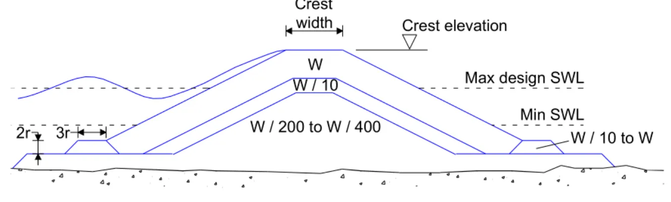
Whilst there is only limited guidance available on the design of simpler rock structures, a wide range of different structures have been constructed. The examples illustrated in Figures 1 to 5 demonstrate the range of different cross-sections in use. A typical cross-section for a relatively conventional rock mound breakwater with multiple layers is shown in Figure 1..
Crest elevation Crest width Max design SWL 2r 3r Min SWL W W / 10 W / 200 to W / 400 W / 10 to W
Figure 1 Conventional breakwater cross-section, SPM (1984)
The CIRIA Rock Manual edited by Simm (1991) shows a groyne cross-section (Figure 2 below) from the Atlantic Coast of North Carolina, USA which follows a broadly similar pattern with armour and underlayers following filter rules (although in this case the underlayer is W/15) and a bedding layer provided to ensure a uniform foundation with minimal settlement into the substrate.
CSG 15 (1/00) 4
Bedded quarry run
Two-layer armour stone 1800-3600 kg 3.0 m 2 1 Elevation 1.5 m above to 1.5 m below MSL UL 90 -270 kg
Figure 2 Conventional rock groyne cross-section, after Simm (1991)
In practice some designers have adopted simpler structures using a single grading of armour, often with an excavated foundation and bedding layer although sometimes placed directly onto a substrate with or without a geotextile filter. One example of this is the nearshore breakwaters at Elmer which are illustrated in Figure 3. The armour is from the ‘standard’ Rock Manual 6-10 tonne grading and was sized using the van der Meer equations for static stability during the design event.
Armour stone (6000 - 10000kg) Bed stone 1 1.5 4.0 m Landward 1 2 Seaward Sand Chalk 6.0 m 0.6 m
Figure 3 Elmer breakwater cross section, after Holland & Coughlan (1994)
‘Reef’ breakwaters developed in the USA and described by Ahrens (1987) and Chasten et al
(USACE 1993) are illustrated in Figure 4. They use a similar cross-section to that applied at Elmer, but are designed to be dynamically stable with the armour grading typically encompassing the range of material that would be used for the primary armour and first underlayer in a conventional, statically stable structure. These structures have a low crest and high porosity which increases the armour stability (but will also increase the amount of wave energy passing the structure) and are resilient to damage – since they have no core they will not suffer catastrophic failure. Once constructed they are expected to adjust and deform under wave loading, but are designed such that they will continue to provide the required performance.
Bedding stone 1.5 m Armour stone 1.5 1 MLW + 0.9 m MLW MLW - 0.45 m
Figure 4 ‘Reef’ breakwater cross section (after USACE 1993)
A similar approach has been used for groynes in the UK, although in the example below (Figure 5) the bedding layer was omitted since the structure was founded on a hard stratum underlying the beach.
CSG 15 (1/00) 5
Firm base level - identified on site Initial beach nourishment level Existing beach level 3.0m 1.5 1
Figure 5 Simplified rock groyne cross section used at Mudeford Sandbank
Use of low cost rock structures
The driver for application of unconventional structures has largely been the desire for lower cost structures combined with an acceptance that this will result in reduced, or at least less predictable, performance. Other attributes of these structures include:
• easier (and often quicker and cheaper) construction
• increased construction safety
• reduced environmental impact / damage
• regular monitoring and maintenance requirement
• more adaptable structures which can be adjusted to changing situations
The compromise between cost and performance is likely to be most beneficial where maintenance is relatively easy and a reduction in the integrity or performance of the structure will not jeopardise the success of the scheme. The former will require easy access to the structure and plant and materials to be readily available, the latter will require an understanding of the functioning and performance of the scheme as a whole and good monitoring arrangements. Most beach control and coast protection structures function in a predominantly morphological manner with the structures influencing the long term development of the beach, but providing minimal protection in the event of a storm. However, structures such as revetments protecting tidal flood embankments provide critical performance during storm events and any failure could be catastrophic. In these situations the inherent uncertainties associated with the performance of simplified structures is likely to make them unsuitable. Indeed, conventional structures will continue to be preferred in many circumstances, particularly where there are significant assets being protected.
The guidance summarised in the project report is not intended to replace any aspect of existing design references, but rather to complement them by describing a different approach which may be appropriate in certain situations. It is not intended to be prescriptive and due to the nature of the research cannot be considered comprehensive, but it is hoped that it will advance best practice by providing a checklist of issues to be considered in developing lower cost coastal rock structures. REDUCING COST
There are three fundamental ways in which the cost of coastal rock structures can be reduced. These are described in the following sections:
Less rock
The size and shape of rock structures (their ‘geometrical design’) is determined primarily by functional and performance requirements such as the degree to which a beach is protected or the
CSG 15 (1/00) 6
proportion of longshore transport trapped by a groyne. However, within the geometrical envelope some aspects of the structure design are dependent solely on the size of the rock armour, for example the layer thickness and crest width are often defined as two or three rocks. If analysis or alternative structural configurations (such as the introduction of a more permeable core) can facilitate a smaller grading of armour, the volume of rock required can be significantly reduced providing both cost and environmental savings.
Other strategies for reducing the quantity of rock used are to replace parts of the rock with alternative materials. This might involve the construction of the core of the structure from waste materials such as old car tyres or employing composite structures where rock is used for some parts and other structural configurations adopted where they provide savings (such as vertical timber or steel panels at the landward end of a groyne). The increased monitoring and adaptability of rock structures may also enable designs to be less conservative, initially using only the minimum quantity of rock
expected to provide the required performance in the knowledge that the structure will be monitored and can be enhanced if required.
Cheaper rock
The cost of rock supplied to site can vary by as much as 25% of the average depending on the state of the market, and the more choice of supply the greater the likelihood will be of obtaining economic materials. Limiting the size of armour required and developing alternative designs to accommodate constraints (such as material properties) imposed by local quarries can enhance choice.
Where there are local quarries within a short distance of the site it may be possible to obtain rock at an attractive cost, but there may be concerns relating to the quality, grading of the armour and the rate of production. Many of these concerns can be overcome by measures such as stockpiling armour prior to the commencement of the main contract, widening the armour grading to utilise a greater proportion of the quarry yield or relaxing the quality requirements and making provision for importing additional armour during the life of the scheme. Where there is difficulty in obtaining a sufficient volume of the largest armour grading selective placement can be used - placing the largest armour in the locations where greatest damage is expected (such as the crest and toe of structures or the outer end of a groyne) providing the increased cost and difficulty of construction do not outweigh the benefits.
Easier construction
Careful design and detailing of rock structures, together with reduction and appropriate allocation of risks can significantly reduce construction time and costs. The use of simpler cross sections, with fewer different gradings of rock will reduce the number of construction operations and the degree of checking required. This in turn will make construction quicker and the use of a single grading of armour will also minimise the risk of damage to the structure during construction.
Reducing the Contractor’s risks by agreeing to payment by weight of rock armour or enabling a clear definition of what is required at the start of the project (through the use of a trial panel of measured density incorporated into the works) is also likely to reduce construction costs as will the sensible programming of works. Construction duration often has a significant impact on construction costs and, where possible, opportunities for enabling maximum utilisation of plant, through night and tidal working (on at least the most restricted or critical elements of the scheme) should be embraced. It is important when considering costs that there is a good understanding of the working methods likely to be adopted and the influence of different issues on construction. This may be best
developed by a partnership approach between the client, designers and contractors, indeed in many cases it is likely that this is the only way in which the full benefits of lower cost structures be achieved
CSG 15 (1/00) 7
since savings will be difficult to quantify on paper and lessons learnt will need to be fed back into the design process.
DESIGN AND ASSESSMENT
Established design guidance and techniques are based largely on empirical evidence, including monitoring of the performance of existing schemes and small scale model testing, rather than scientific theories or reasoning. Much of the guidance provides the designer with arbitrary limits on allowable parameters for acceptable performance, but no understanding of how performance is changed if the parameter is varied. The design and assessment of coastal rock structures requires analysis and an understanding of a range of different issues including:
• performance and functional requirements
• technical feasibility and engineering practicality
• environmental impacts
• safety considerations
• cost
Each issue will have to be assessed and balanced against the others, eventually resulting in a compromise acceptable to the various parties. Cost was discussed in the previous section and the impact of adopting simplified structures on each of the other issues is described below:
Performance and functional requirements
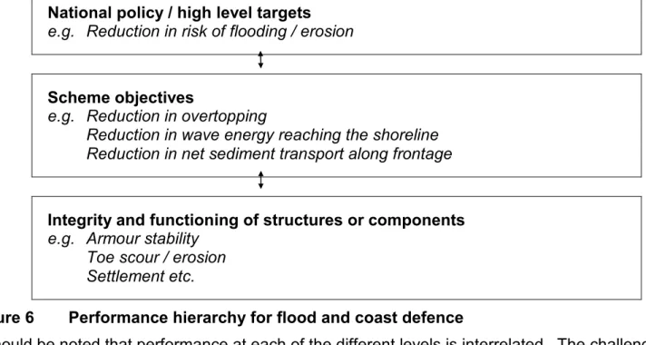
A clear understanding of performance requirements for schemes and individual structures is vital if coastal rock structures are to be both efficient and effective. Unconventional structures may not be intended to deliver the same performance as more established (and expensive) designs, but they must still enable overall scheme requirements to be met. This is best understood in a hierarchical way relating to the system of flood and coast defence being delivered, illustrated in Figure 6.
National policy / high level targets
e.g. Reduction in risk of flooding / erosion
Scheme objectives
e.g. Reduction in overtopping
Reduction in wave energy reaching the shoreline Reduction in net sediment transport along frontage
Integrity and functioning of structures or components
e.g. Armour stability Toe scour / erosion
Settlement etc.
Figure 6 Performance hierarchy for flood and coast defence
It should be noted that performance at each of the different levels is interrelated. The challenge in reducing the cost of structures is to identify more precisely the particular performance that is necessary for the overall scheme to function. This can lead to a considerable relaxation in the performance requirements for individual scheme elements - in the case of a scheme comprising
CSG 15 (1/00) 8
beach nourishment and rock groynes, the main function of the groynes is to retain the beach. If the beach needs substantial renourishment or reinstatement following significant storm events it may not be appropriate to design the groynes to withstand a more extreme event without any damage.
Technical feasibility and engineering practicality
The designer must have a good understanding of the basis, sensitivity and reliability of the methods used in the design. The arrangement adopted should be checked for behaviour in extreme events to provide an indication of likely damage and failure mechanisms. Design assumptions also need to be reviewed to ensure that they are valid and particular attention should be paid to site investigation (including both topographic levels and geology) immediately prior to construction. The way in which the structure will be constructed and maintained must be considered from the outset of scheme development. This will assist in avoiding details which are very difficult, dangerous or expensive to construct, and will require an appreciation of different construction methods, plant and costs. Such input may best be provided by an experienced contractor and will help ensure that the design can be successfully implemented and may be used to assist the estimation and optimisation of costs.
Environmental impacts
Environmental issues associated with coastal rock structures include visual / landscape impacts, recreational benefits and the provision of marine habitat. The latter is well described in ‘Design criteria for enhancing marine habitats within coastal structures: a feasibility study’ (Halcrow et al 2001) which describes how ecological benefits may be facilitated by:
• improved shelter from currents and waves
• inclusion of preferred internal gallery structure
• increased roughness and range of cracks / fissures within structural units
• spreading of isolated structure units, set apart from the main reef structure
The total structure size and range of internal void spaces are likely to be smaller for lower cost structures than conventional structures and the structure is likely to be disrupted (damaged and repaired) more frequently. However, lower cost structures will generally require less disturbance of the beach during initial construction activities and will have a lower impact on the visual landscape and wider environment through the use of less material. Thus it is likely that lower cost rock structures will have a substantially similar or smaller environmental impact when compared with conventional rock structures.
Safety considerations
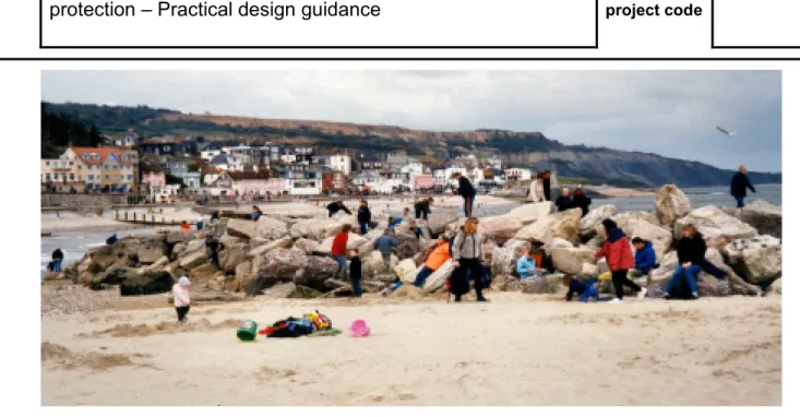
In considering safety both the general public and those constructing and maintaining structures must be considered. Public safety of access to various coastal structures has been considered in an earlier study, see Halcrow (1996) and Heald (2002). Although public access is seldom a primary requirement for coastal rock structures, designers must be aware that the public are likely use anything to which they can gain access for amenity (even if signage suggests that this is unwise). For coastal rock structures public safety will be primarily related to access to and on the structure(s). Some hazards are inherent to a greater or lesser degree in all coastal rock structures including:
• potential for falls
• slip / trip hazards
• trapped limbs
• cut / stab hazards
CSG 15 (1/00) 9
Figure 7 Public use of a rock structure at Lyme Regis for recreation
The adoption of lower cost structures offers a significant opportunity to improve public safety. The use of smaller armour and / or overall structure dimensions together with tighter packing and
increased care with which the armour is placed should reduce the effect of falls (since the structures are likely to be smaller) and lead to smaller voids between armour stones reducing the risk of trips, slips and trapped limbs. Public safety could, however, be adversely affected by damage to the rock structures resulting in displaced and / or unstable armour – in such circumstances it may be
necessary to restrict access to the structure(s) until repairs are effected. Decreased reliability in the performance of a structure (possibly leading to increased cliff erosion for example) may also threaten public safety during service.
The safety of those building lower cost structures should be improved; since they are built more quickly, overall exposure to danger during construction will be reduced. As lower cost structures generally require less foundation preparation, there is also likely to be little or no requirement for deep excavation within the beach. The use of fewer armour gradings will mean there is less need to check the levels of layers. The omission of underwater geotextile or complex granular filters requiring diver operations would also substantially increase construction safety.
DESIGN AND DETAILING FOR LOWER COST
A number of methods and design details have been identified during the study which may assist in the design and detailing of lower cost rock structures. Many relate to the accurate determination of appropriate armour size (which may be assisted by recent research) but others are also described below:
Armour sizing for depth-limited locations
Within the ‘Rock Manual’ (Simm 1991), it is suggested that H2% wave height may be more
appropriate than Hs for use in depth-limited conditions, and van der Meer provided revisions to his equations using the relationship between H2% and Hs for deep water. The manual suggests that H2% may be estimated for depth-limited conditions from Goda’s equations (which give Hs and H0.4%). The reasoning behind this is the assumption that largest waves cause most damage and that by correctly abbreviating the wave height distribution, a smaller armour size can be justified.
Estimating H2% from Goda’s Hs and H0.4% is however not well justified. Fortunately, research into wave height distributions on shallow foreshores has recently been presented by Battjes &
CSG 15 (1/00) 10
Groenendijk (2000). The scientific theory underlying this work is complicated, but a simple method has been developed to assess the wave height distribution based on the nearshore wave energy, local bed slope and water depth. This approach is particularly useful in that it will allow output from calibrated cross-shore numerical models (frequently used to assess beach profile response) to be extrapolated to provide H2% at appropriate locations. The data may also be used to improve the estimation of H2% from calculations using Goda’s formulae.
It remains important however, to assess wave conditions at an appropriate location relative to the structure. This is because total wave energy is not immediately decreased on wave breaking, but continues to propagate inshore for some distance. Within Goda’s formulae the water depth at a distance of five times Hs from the point of interest is used and normal practice for the application of van der Meer’s equations has often been to use wave conditions at a distance of two or three wave lengths from the toe of the structure.
Performance of tightly packed armour layers
Research has also recently been completed by Stewart (2002) into the hydraulic performance of tightly packed armour layers. This study demonstrated that the stability of armour layers increases significantly if rock armour is placed closely to achieve a tight packing, but that dissipation of wave energy was not greatly affected by this reduced porosity (within the range tested).
Stewart (2002) concludes that the parameters given in van der Meer’s equations for bulk-placed rock (Cpl=6.2 and Csu=1.0) are appropriate for armour layers where the void porosity approaches nv = 40%. If, however the porosity reduces to below nv = 35%, then stability increases significantly and revised values (Cpl=7.8 and Csu=1.8) are more appropriate. It should be noted that the minimum porosity tested for armour stability was nv = 34.5% and it is not appropriate to extrapolate higher values for the stability coefficients from lower porosity values.
Using wider gradings
When using wider than normal gradings (D85/D15 < 1.5), there is greater potential for the smallest rocks to become dislodged from the body of the structure, which will ultimately lead to a decrease in the stability of the armour layer. Anecdotal evidence suggests that providing the grading is not excessively wide (D85/D15 < 2.5) and the structure slopes are not too steep (Cot α >2.5 or 3) the use of wide gradings is unlikely to result in significant problems. Allsop (1990) showed that very wide grades (2.5 < D85/D15 < 4) were not desirable due to the high risk of spatial variation and local failure. The majority of the structures studied during the course of this study did not use standard armour gradings as defined in the ‘CIRIA Rock Manual’. This may partly be due to the fact that some were designed before publication, but also reflects the willingness of some designers to base the structure on materials available locally or at an advantageous price.
Selective placement of armour
One technique which has been associated with the use of wider gradings, but which may also be used where there is a concern that the armour stability is marginal, is the selective placement of the largest rocks in the parts of the structure where greatest damage is likely to occur, as illustrated in Figure 8. It is important that the contractor is fully aware of such a proposal at the time of tendering as the selection and setting aside of the largest rocks can incur significant effort during construction. A requirement to place large rocks at the crest of the structure, for instance, might have implications for the selection of plant. The specification of such selective placement may best be formalised through the creation of a sub-grading for the largest rocks which can be separately priced if appropriate.
CSG 15 (1/00) 11 2.5 1 3.0 m
Approximate level of bedrock
Coarse filter (60 kg to 3000 kg)
Selected heavy armour
(11000 kg to 12000 kg) Heavy armour
(8000 kg to 12000 kg)
CL 5.0 m
Figure 8 Selective placement of larger rocks
A similar approach can also be applied to the plan shape of some structures. For example the head of a rock groyne is often subject to much greater loading than the trunk or root of the structure. If the supply of the largest armour is severely limited, it may be sensible to use that armour on the outer part and vary the grading along the length of the structure.
Toe details
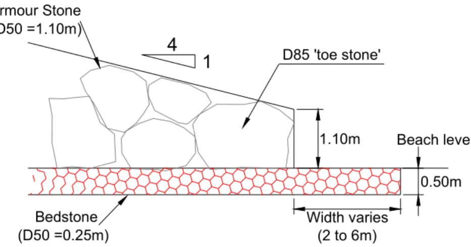
Rock structure toe details deserve particular attention; they are often exposed to the most severe wave climates and are most difficult to construct (often with a very small working window due to the returning tide or ground water within the beach flooding any excavation). The base of the toe detail will be dependent on an assessment of the maximum depth of scour and the depth of mobile beach in front of the structure. Where the beach is relatively thin and over lies a strata which will not easily be eroded it may be possible to adopt a relatively simple toe detail as shown in Figure 13. This uses a selected larger rock to provide stability and a good starting point for the structure at the toe and a blanket of bedding material to prevent scour due to reflection from the ‘toe stone’.
Beach level 4 1 Armour Stone (D50 =1.10m) 1.10m Bedstone (D50 =0.25m) D85 'toe stone' Width varies (2 to 6m) 0.50m
Figure 9 Toe detail from a fishtail breakwater at West Shore, Llandudno
Filter criteria
Traditionally breakwaters have been constructed from cores of fine material (often quarry run) with various gradings of underlayers sized using established filter rules to prevent migration of the core through the outer layers. In many cases the use of fines in beach based structures provides no function or saving and may be omitted. Where filters are required, some evidence suggests that the ‘rules’ might be relaxed (perhaps substantially in some conditions) so that the ratio of the average weight of the cover layer to underlayer (WA/WU) might be as high as 40.
CSG 15 (1/00) 12
It has long been claimed that rock structures can easily be adjusted, repaired or modified during the scheme life. In reality the use of different gradings, multiple layers and prepared foundations can result in this being difficult and uneconomic. Thus whilst timber groynes may be adjusted annually, rock groynes have largely been perceived as unchanging and designed for minimal maintenance or repair. Increasing the ease with which such structures can be modified, and accepting an ongoing requirement for monitoring, repair and adjustment may provide several advantages:
• Design of structures could become much less conservative
• Structures may be optimised to provide desired performance as requirements or conditions change
• Temporary structures could be used to provide short term or seasonal protection at ’hotspots’ Increased adaptability is particularly valuable for coastal structures due to the inherent variability and uncertainty in both loading conditions and performance. This will, however, require the ability to deliver relatively small quantities of rock to sites to allow enhancements to take place or stockpiling of rock at the time of initial construction (which may negate some of the cost savings).
Conclusion
Many of the structures reviewed during the study were markedly different from conventional designs. The variations are believed to have provided significant cost savings whilst maintaining acceptable performance and there is clearly considerable potential for the wider application of this type of structure. Although the limited number of cases reviewed mean that no quantitative guidance could be developed the design methods and details discussed are thought to be widely applicable and may be adopted immediately .
ACKNOWLEDGEMENTS
This paper is based on studies funded by Defra which results are published in the report “Low cost structures for beach control and coast protection: Practical design guidance” (Crossman, MP, Segura-Domínguez, S & Allsop, NWH, Defra / Environment Agency R&D Technical Report CSA 6020, May 2003). The report authors (Matt Crossman, assisted by Silvia Segura-Domínguez and William Allsop) are particularly grateful to the study team (Phil Barber, Ron Gardner, Jentsje van der Meer, Michael Owen, Will Shields and Paul Starr), Frank Tyhurst, Steve Woolard, Bob Kidd and all those who provided case study information
REFERENCES
Ahrens, JP. (1987) Characteristics of reef breakwaters. CERC Technical Report 87-17, US Army Engineer Waterways Experiment Station.
Allsop, NWH. (1990) Rock armouring for coastal and shoreline structures: hydraulic model studies on
the effects of armour grading. Report EX 1989, HR Wallingford.
Battjes, JA & Groenendijk HW. (2000) Wave height distributions on shallow foreshores. Coastal Engineering, Elsevier, Rotterdam. Volume 40, 2000, p.161-182.
Coastal Engineering Research Centre, CERC (1984) "Shore Protection Manual" 4th ed. U.S. Govt. Printing Office, Washington D.C.
Crossman, MP, Segura-Domínguez, S & Allsop, NWH. (2003a) Low cost rock structures for beach
control and coast protection: Practical design guidance. Defra / Environment Agency R&D Technical
CSG 15 (1/00) 13
Crossman, MP, Bradbury, AP, Allsop, NWH & Segura-Domínguez, S. (2003b) Low cost rock structures for beach control and coast protection to be presented in 38th Defra Annual Flood and Coastal Management Conference, July 2003.
Halcrow (1996) Public safety of access to coastal structures. Final report to Stage 1 of R & D project 522, National Rivers Authority, Bristol.
Halcrow Maritime in association with Southampton Oceanography Centre and CEFAS (2001). Design criteria for enhancing marine habitats within coastal structures: a feasibility study. Available from: http://www.defra.gov.uk/research/Publications
Heald, G. (2002) Design on the Rocks? in Proc. ICE Breakwaters, coastal structures & coastlines Thomas Telford, London.
Holland B. & Coughlan P. (1994) The Elmer Coastal Defence Scheme in Proc MAFF conference of River and Coastal Engineers. MAFF, London.
Simm, JD ed. (1991) Manual on the use of rock in coastal and shoreline engineering CIRIA / CUR, Special Publication 83. CIRIA, London.
Stewart TP. (2003) Packing and voids for rock armour in breakwaters. Report SR 621, HR Wallingford.
USACE (1993) Engineering design guidance for detached breakwaters as shoreline stabilization
structures. Technical report CERC-93-19 U.S. Army Engineer Waterways Experiment Station.
USACE (2003) Coastal Engineering Manual. Engineer Manual 1110-2-1100, U.S. Army Corps of Engineers, Washington DC (in 6 volumes).