(IJSBAR)
ISSN 2307-4531
(Print & Online)
http://gssrr.org/index.php?journal=JournalOfBasicAndApplied
---
215
Quality of Service (QoS)-Based Network Resource
Allocation in Software Defined Networking (SDN)
Nwe Thazin
a*, Khine Moe Nwe
b a,bUniversity of Computer Studies, Yangon, Myanmar (UCSY)a
Email: [email protected] b
Email: [email protected]
Abstract
With the rapid growth of network technologies, the development of the domain is shifting from providing connectivity to providing a number of services and applications with desirable quality. These applications and services have different service features and their own quality demand. Therefore, implementing a network which can provide accessible performance for all traffic types becomes a very hard challenge. In this paper, we present a resource allocation scheme for bandwidth allocation that satisfies Quality of Service (QoS) requirements for all priority flows by using Open vSwitch, based on Software Defined Networking (SDN). The main goal of this system is to provide high QoS performance for high priority flows. The effectiveness of the proposed scheme is described on the emulated SDN network. The proposed scheme is compared with the conventional shortest path scheme, multipath routing scheme in simple network topology. The results of the experiments showed that the proposed approach achieves better performance in terms of throughput, end-to-end delay and packet loss rate than that of traditional shortest-path and multipath routing.
Keywords: Resource Allocation; Quality of Service; Software Defined Network.
1.Introduction
The current network architecture is to provide the satisfaction of network users (customers).
--- * Corresponding author.
216
From the network operator point of view, the network operator needs to use the available network resources and better QoS management for end user to deliver the better performance due to a variety of emerging internet based applications and numeric services over the network, such as multimedia streaming, online gaming and Voice Over IP (VoIP), etc. These diverse services and applications need steady network resources with different subsets of relevant QoS requirements and different priority. QoS is a solution to provides performance guarantees for applications services with the way of managing network resources efficiently. Quality of Service (QoS) is the ability to satisfy the requirement of specific traffic. Lots of today network applications require certain QoS guarantees. For example, an application like video streaming requires the small delay while data communication is less sensitive to delay, but more sensitive to packet loss. The network should be supplemented to provide some appropriate level of quality for these applications. Typically, this requires extending the network software to provide a certain level of quality in delay, jitter and potential loss of data. In today's life, it is general that many applications run at the same time. As a critical type of resource, bandwidth would be shared without principle which leads to interference. Therefore, high priority flows (importance applications) cannot get enough bandwidth to transmit data. Increasing bandwidth is a common solution to adequately accommodate the real-time applications like VoIP, but it is still not adequate to sidestep jitter during traffic bursts. The dynamic link bandwidth allocation with congestion management that can support the QoS requirements for each traffic and mitigate the service degradation for high priority flows. In this paper, we consider network bandwidth as the network resource and try to allocate the user’s requests in the SDN environment. The goal is to improve the link utilization while reducing the packets loss rate as the QoS factor in the overall network. To realize this goal, the proposed scheme tries to allocate the network traffic dynamically by considering the flow priority and the dynamic characteristics of the network. In addition, feasible paths are calculated for all the traffic flows that can satisfy the user bandwidth demands. In order to mitigate the flow performance degradation and congestion, the controller checks the link bandwidths by reserving the required bandwidths for incoming flows. If the link bandwidth is smaller than the predefined threshold value, the link is defined as the bottleneck link and reroute the highest priority flow from the bottleneck link to an alternative link that has enough bandwidth for the rerouting flow. Furthermore, to improve the performance and to ensure the QoS of the high priority flows, a queue mechanism is used which is provided by the OpenFlow at the data link level. This system will try to accommodate the general mix of QoS traffic types and study the effect of QoS routing on them.
2.Related Works
This section covers an existing literature review of traffic engineering and resource allocation for SDN based networks. In a network, a lot of real-time traffic, such as voice data, instant messages and so on, is sensitive to delays and packet losses in the process of transmission. Therefore, reasonable allocation of network resources to provide QoS is an important problem of traffic management. Therefore, most of the researchers try to design the dynamic resource allocation scheme and traffic scheduling algorithm to meet users' requirements. Some research works studied the SDN control framework and flow rerouting schemes to provide the end-to-end QoS provisioning. In [1], Jaward and his colleagues proposed a policy-based QoS management framework to achieve end-to-end QoS with rerouting and rate limiting. In [2], Chenhui and his colleagues proposed a QoS-enable management framework to guarantee the QoS of specific flow and employ the queue technique and policy to satisfy the requirement of service. Flow rerouting is carried out on the priority flow in order to mitigate
217
the impact on best-effort flow. Tomovic and his colleagues [3] presented a new SDN control framework for QoS provisioning. The framework could provide the required QoS level for multimedia applications automatically and flexibly. They aimed to minimize the best-effort traffic performance degradation. They estimated the link utilization by using a threshold value (80% of the link) and rerouted the best-effort traffic before congestion occurs. On the other hand, some works are trying to place flows based on minimum link utilization and independent of flow size. In [4], F.P.Tso and D.P.Pezaros introduced Baatdaat, measurement-based flow scheduling for reducing congestion in data center networks. It used the lightly-utilized paths and allows flow rerouting to schedule traffic flows. Furthermore, there are many kinds of solutions have been proposed to guarantee QoS requirement in SDN network. OpenFlow supported queue scheduling is the most common tool to implement QoS control for individual flow in the data plane. It can be used in providing bandwidth guarantees by shaping and prioritizing traffic to share the network bandwidth [5]. In [6], Boley and his colleagues developed a QoS framework to achieve optimal throughput for all QoS flows with the help of meters’ function. In [7], Li and his colleagues implemented a queue scheduling technique used on SDN switches to achieve QoS for cloud applications and services. The current work in SDN based traffic optimization focuses on improving the quality of individual applications and services such as video streaming or voice communications in several different network environments. To improve the quality of individual network flow, SDN has to come with solutions to a number of problems. Some of them have been addressed in the literature review. However, quality of service capabilities of all the different components of SDN with the traffic priority will also play a major role in the widespread adoption of SDN in the real internet.
3.Architecture of Proposed Resource Allocation Scheme
In this section, the overall architecture of proposed resource allocation scheme based on SDN is described in Figure 1.
Figure 1: Architecture of Proposed Resource Allocation System
The resource allocation system should have a good knowledge of the network resource utilization state such as available bandwidth, network load and delay. Therefore, we implement the fundamental network modules such as topology discovery module, network monitoring and delay estimation module which can be used to coordinate the allocation of the network resource. Beside, our system includes two more main modules: QoS
218
routing module and Congestion Handling module which are supported to provide required QoS for the difference type of flows. Each module has its own functions and they are linked with each other in the proposed scheme.
3.1 Topology Discovery Module
This module is used to discover the SDN switches connected to the controller and have knowledge of the links between them to calculate a route for the network connection. Although there is no specific standard for discovering the topology of an OpenFlow-based SDN, most SDN controllers’ implementations follow the OFDP protocol relying on LLDP packets [8]. Firstly, the topology discovery module firstly sent out the Link Layer Discovery Protocol (LLDP) packets to all the connected switches through packet_out messages to acquire topology and connection information. After that, the messages instruct the connected switches to send LLDP packet_out messages over all its ports to other connected devices. Then this message would be delivered to the controller as packet_in messages since the switch does not have a flow entry for this LLDP message. These packet_in messages contain information about switch’s port that the specific host connects to. SDN controller creates a connection based on these packet_in messages. In this way, global topology information can be gained.
3.2 Network Monitoring Module
This module is used to do real-time measurements of the network. It is very hard to calculate the route without knowing link load information for all the relevant links. However, SDN solves the problem and makes it much easier for both users and operators because the controller already has the global network view and access to all the information of topology. The controller keeps tracks of how much bandwidth is allocated in the network. Monitoring module tracks the amount of traffics by periodically polling flows statistics such as received and transmitted bytes or packets from all connected switches and takes snapshot the current network status. The module calculates link utilization and available bandwidth for bandwidth allocation. To calculate the link utilization of each link i for every time unit can be computed by using the number of transmitted bytes from the port statistic as follows:
LUi= [ B(i, tj +1) –B(i, tj)] / [(tj +1) – (tj) ] (1)
Where tj, tj+1 indicate the two consecutive responses time and the number of transmitted bytes reported at time tj for link i is denoted as B (i, tj). B (i, tj + 1) indicate the number of transmitted bytes reported at time tj+1. Then, the available bandwidth (ABWi) of each link can be computed simply by subtracting the link utilization (LUi ) from the network bandwidth capacity (BWi ) as follows:
ABWi=BWi - LUi (2)
After calculating available bandwidth, the monitoring module sends this information to the QoS routing module to compute routes to deliver the traffic form the source node to the specific destination node.
219
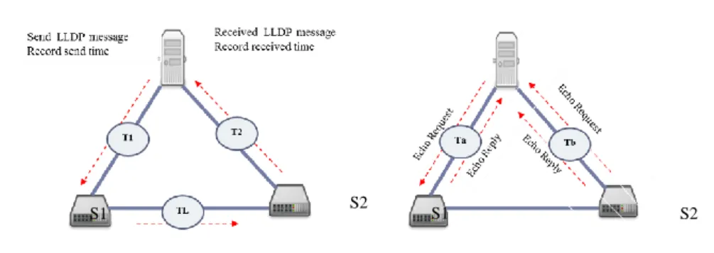
This module is responsible to estimate real-time delay of the network. This module adopts the LLDP protocol which is describe in the topology discovery module since the SDN controller discovers all the links, in both directions, to updates its view of the network periodically. Equation (3) is used to estimate the delay of the link:
T=(T1+T2-Ta-Tb)/2 (3)
To get the logic, the controller sets the timestamp in the beginning of the LLDP data transmission, and then subtracts the received timestamp to estimate the delay from the controller to the switch S1. Then, from switch S1 to switch S2, and then report the delay T1 to the controller, an example is shown in the Figure 2. The same inverse delay T2 consists of red arrows. After that, this module needs to test the echo round-trip delay between the controller and the switch, Ta, Tb. The measurement method is as follows: the controller sends a time-stamped echo_request message to the switch, and then parses the echo_reply returned by the switch, and subtracts the sending time of the data part from the current time to obtain the round-trip time difference.
(a) (b)
Figure 2: Delay Estimation Work Flow. (a) Message exchanged between the controller and OF switches with
LLDP-based topology discovery (b) Message exchanged between the controller and OF switches with echo-request and echo-reply
3.4 QoS Routing Module
The main function of this module is to find the best path to alleviate network congestion and improve the QoS of network applications such as media streaming and online games which require the strict QoS guarantees. This module uses the network topology information from the topology discovery module and the traffic statistics from the monitoring module to compute multiple paths, and pushes the resulting computation as flow rules to the SDN switches. Route calculation module calculates the shortest path tree from each source node to all the destinations by applying a shortest path finding algorithm, Dijkstra. Whenever a new flow with bandwidth request arrives which may include source (s), destination (d) and requested bandwidth (r), the controller allocates the demand flow based on the current link utilization. After calculation possible path lists, check the available bandwidth of the path which can be implemented by using the statistic of the network monitoring module. If it is enough for the bandwidth guarantee rate, the controller selects the path as the optimal candidate path for routing. If it is not enough, the link is simply remove to avoid the link performance degradation. After selecting the routing path, the controller updates the flow table of the switches along the path. Then, QoS
220
mapping is implemented for QoS flow with priority queue to provide bandwidth guarantee. The hierarchy of the proposed QoS routing work flow has described in Figure 3.
Figure 3: Hierarchy of QoS Routing
Let us consider the network traffic as in three classes: two QoS classes and best-effort class (non-QoS). Whenever a new flow is arrived, the controller extracts flow information such as source node, destination node and request bandwidth. The controller checks the flow priority information which can show the incoming flow is QoS class types or best-effort (BE) class. In the proposed scheme, the routing engine firstly finds the most feasible path for required QoS. A feasible path can provide sufficient resource r to satisfy all the QoS requirements of the flow. For example, if the incoming flow type is the bandwidth demand QoS class or the BE class, the QoS routing module chooses the maximum available bandwidth path by calculating link utilization. For the minimum delay demand QoS class flow, the QoS routing module calculates the link delay between the source and the destination nodes. Then, choose the minimum delay paths in order to meet the QoS requirement of the flow. After the path is calculated, SDN controller installs flow entries to each switch along the path and update the flow database of the switches along the path. Then, QoS mapping is implemented for QoS flow with priority queue to provide bandwidth guarantee. Ovs Switch can forward packet by using the flow rule.
3.5 Congestion Handling Module
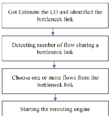
The aim of the congestion control module is to provide services to its users that meet certain performance criteria, often represented by a set of QoS parameter. One of the challenges in meeting QoS requirements is avoiding bandwidth starvation of certain traffic type by others. Flow rerouting is one of the ways to deal with the QoS degradation of the flows in heavy network. A natural method for congestion control is using the low load path. Such routing also achieves load balancing of the network resources. The controller needed to reroute some of the current flows on the bottleneck link is detected to mitigate the flow congestion. Figure 4 shows the work flow procedure of the flow rerouting and the proposed flow rerouting algorithm.
User request D (s, d, r)
Check the preference QoS class and the amount of bandwidth
Queue as policies and reserve bandwidth If QoS class is bandwidth or BE, find the
maximum available bandwidth path.
If QoS class is delay, find the minimum delay path.
221
Figure 4: Workflow to Start the Flow Rerouting
The proposed scheme attempts to avoid traffic congestion when a new flow is added to the link. The accepted flows bandwidth is investigated by reserving the required bandwidths (r) for incoming flows to know the maximum bandwidth usage (Mbw) by Equation (4):
Mbw (new) = Mbw (old) + r (4)
After calculating the maximum bandwidth usage, the controller checks whether the usage bandwidth exceeds a predefined threshold to identify the bottleneck link. Identifying the network link bottleneck is very useful for both end users and services providers. By identifying the bottleneck link, the proposed system can eliminate paths that have lower bandwidth and reroute the traffic over the bottleneck link to an alternative path with the highest bandwidth by using QoS routing. If the link bandwidth is greater than the predefined threshold value, we define the link as the bottleneck link and reroute the highest priority flow from the bottleneck link to an alternative link that has enough bandwidth for the rerouting flow.
4.Test-Bed Environment
In order to evaluate the performance of the proposed resource allocation scheme, the experimental test-bed has to be designed. All network topologies are emulated on an Ubuntu 16.4LTS virtual machine. The emulation is conducted using a network topology including one controller, four switches, and seven hosts as shown in Figure 5. Mininet [9] is used for the network emulation in all the experiments. The network topology is implemented by using python script in the Mininet emulator. The Open Virtual Switches (OVS) [10] are used in the network topology. All the network links between OVS switches have been set to 10 Mbps, and the capacity of the output ports in all the OVS switches are also 10 Mbps. Hosts h1, h2, and h3 are traffic senders, and h4, h5, h6, h7 are the traffic receivers via OVS switches s1, s2, s3, s4. OVS switches s2 and s4 are the intermediate switches in the prototype.
222
Figure 5: Simple Network Topology with Link Delay Parameter
5.Evaluation Method
This section investigates the performance of the proposed resource allocation scheme. The analysis consists of end-to-end measurements of throughput, delay and packet losses for UDP and TCP connections with different traffic patterns. In order to simulate the UDP traffic, the DITG [11] network test tool is customized and seven flows are generated. To observe the flow performance for the proposed scheme, two minimum delay demand flows, two bandwidth demand flows and three best-efforts traffic flows are used with various packet size and rate. The minimum bandwidth request ratios for both QoS flows and cross-traffic are shown in Table 1.
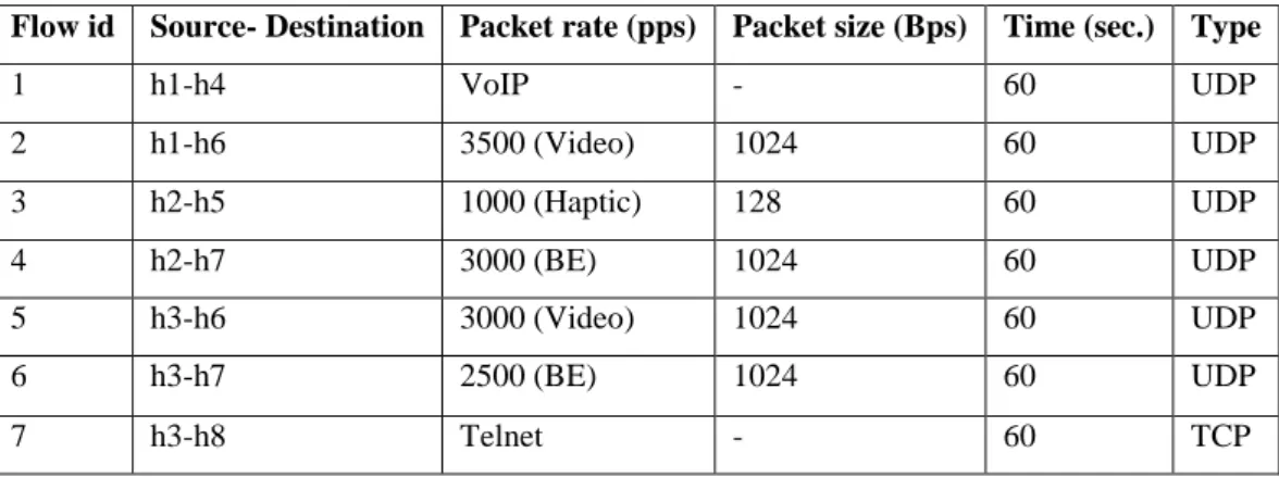
Table 1: Network Experiment Flows for Simple Network Topology
Flow id Source- Destination Packet rate (pps) Packet size (Bps) Time (sec.) Type
1 h1-h4 VoIP - 60 UDP 2 h1-h6 3500 (Video) 1024 60 UDP 3 h2-h5 1000 (Haptic) 128 60 UDP 4 h2-h7 3000 (BE) 1024 60 UDP 5 h3-h6 3000 (Video) 1024 60 UDP 6 h3-h7 2500 (BE) 1024 60 UDP 7 h3-h8 Telnet - 60 TCP
The host pair (h1-h4) means the traffic from h1 to h4 and it is denoted as minimum delay demand flow (VoIP). The host pair (h1-h6) means the traffic from h1 to h6 and it is denoted as bandwidth demand flow. Then the host pair (h2-h5) means the traffic from h2 to h5 and it denoted as haptic traffic. To limit the maximum and minimum traffic rates for different flows, we set three different queues with different rates for all the egress interfaces of s1, s2, and s4. For this experiment, q0 has with the maximum bandwidth (1 Mbps) for the default demand flow and q1 has the minimum bandwidth (3 Mbps) for the minimum delay demand flow. Then, q2 is configured with large maximum bandwidth (6 Mbps) for the bandwidth demand flow. After setting policies in all the intermediate switches, the two flows from client h1 is sent simultaneously at time zero for 60 seconds. After five seconds later, the other two flows from h2 is sent for 60 seconds while the lest traffic flows from the h3 is start at another 5 seconds later for 60 seconds. According to the prototype network topology, there are three possible traveling paths between traffic senders and traffic receivers.
223
First Path: s1 - s3
Second Path: s1 - s2 - s3
Third Path: s1 - s4 - s3
According to the link delay setting, the first flow from client h1 to h4 will selects the second path (s1 - s2 - s3) which has the minimum delay and reserved the user’s requested bandwidth for it. In the initial stage, there is no other flow is allocated on the network link, the second flow from client h1 to h6 will selects the first path (s1-s3) since the first path has the shortest length. After 5 seconds, h2 request for the two different flows. The first one from client h2 to h5 will selects the minimum delay path among these three possible paths since it is the minimum delay demand flow type. Then, the left flow from client h2 is selected the path with a maximum available bandwidth for it. After 10 seconds later from the most first generated flow, the client h3 request three types of traffic flows and paths are chosen for them based on their demand QoS types. The link will be defined as bottleneck when the total reserved bandwidth over a link is exceeded than the predefined threshold (80%). When the bottleneck link is detected, the highest priority flow will reroute to other best path in order to present bandwidth starvation and packet loss rate for the bandwidth demand flow.
6.Evaluation Results
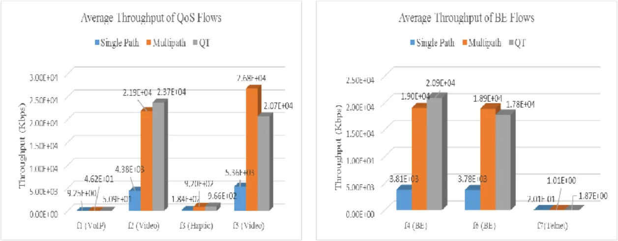
The goal of this experiment is focused on the work of proposed approach in simple network topology by using queuing technique. The performance of the proposed approach will measure with the common QoS parameters (i.e. average throughput, packet loss rate and delay time). Then, the comparison of the experimental results is made by using the proposed scheme with the traditional shortest-path routing scheme and multipath routing schemes. The throughput and packet loss is measured for all traffic flows. The average throughput for both QoS flows types and BE flows types are shown in Figures 6 (a), 6 (b), respectively.
(a) Average Throughput of the QoS flows (b) Average Throughput of BE flows
224
According to Figure 6, the traditional single path scheme has minimum throughput performance than the other two schemes. This is the consequence of using always the same shortest path (s1, s3) for routing. In Figure 6 (a), it can be seen that the throughput of network flows in both multipath and the proposed approach have the high throughput rate than single path routing. This is because all the flows were routed to all the available paths instead of sharing a single path to route flows from the sources to the destinations in both approaches.
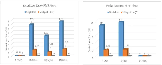
(a) Packet Loss Rate of the QoS flows (b) Packet Loss Rate of BE flows
Figure 7: Packet Loss Rate of the Experiment on Simple Network Topology
The packet loss rate of the three approaches for each flow is shown in Figures 7. According to the experiment results, the proposed approach has the zero or nearly zero packet loss rate for all traffic. In Figure 7, the packet loss rate is high in traditional single-path routing scheme. It is observing that the packet loss rate of our proposed scheme is less than those of the other two schemes. Although multipath have some packet loss rate approximately 1 % in each flow, it can be acceptable and neglectable.
(a) Average Delay of the QoS flows (b) Average Delay of BE flows
Figure 8: Delay of the Experiment on Simple Network Topology
225
both single path and multipath routing schemes. From the experiment results, it is observed that the proposed approach works well and provides better performance in terms of packet loss rate for the QoS traffics. Later, the performance of the QoS routing with large network topology will evaluate.
7.Conclusion
A number of today’s network applications such as media streaming and VOIP services require steady network resources with strict QoS requirements. In general, it is not easy to make sure that efficient bandwidth allocation is done in order to provide high QoS for each data flow. To solve these problems, the QoS-based network resource allocation scheme is proposed to provide the required QoS for various types of traffic based on the user’s QoS demand. The improvement of QoS traffic types are quantified in terms of throughput, delay and packet loss rate, respectively. Based on the experiments, we can observe that the proposed resource allocation scheme offers a significant improvement compared to a static, traditional IP network and the multipath network environment by providing better performance in terms of packet loss rate for the QoS traffics and great improvement in link utilization.
8.Recommendation
SDN is introduced to address the limitation of the traditional network efficiently for modern network architectures like 5G. In SDN, OpenFlow provides flow level programmability to program the network according to QoS requirements of the applications. Although OpenFlow supports the queue features, it does not handle queue management; it is just able to query queue statistics from the switch. Therefore, the proposed system doesn’t provide capabilities for queue management. As the future work, the proposed system can extend to be a more realistic approach by collaborating with an effective queue scheduling in the data plane and apply meter feature of OpenFlow protocol.
References
[1] A. Alijawad, P. Shah, O. Gemikonakli, and R. Trestian. “Policy-based QoS management framework for software-defined networks.” In 2018 International Symposium on Networks, Computers and Communications (ISNCC), pp. 1-6, IEEE, 2018.
[2] C. Xu, B. Chen, H. Qian, “Quality of service guaranteed resource management dynamically in software defined network”, International Journal of Communications, vol. 10, pp. 843-850, 2015. doi:10.12720/jcm.10.11.843-850.
[3] S. Tomovic, N. Prasad, and I. Radusinovic, “SDN control framework for QoS provisioning,” in Proc. Telecommun. Forum Telfor (TELFOR), pp. 111-114, Nov. 2014.
[4] N. L. M. van Adrichem, C. Doerr, and F. A. Kuipers, “OpenNetMon: Network monitoring in OpenFlow software-defined networks,” in Proc. IEEE/IFIP Netw. Oper. Manage. Symp., pp. 1-8, May 2014.
[5] S. U. Baek, C. H. Park, E. Kim and D. Shin, “Implementation and verification of QoS priority over software-defined networking,” In Proceeding of the International Conference on Internet Computing
226
(ICOMP). The Steering Committee of the World Congress in Computer Science, Computer Engineering and Applied Computing (WorldComp), 2016.
[6] J.M.Boley, E.S. Jung, and R.Kettimuthu, “Adaptive QoS for data transfers using software-defined networking.” 2016 IEEE International Conference on Advanced Networks and Telecommunications Systems (ANTS), IEEE, pp. 1-6, 2016.
[7] F. Li, J. Cao, X. Wang, Y. Sun and Y. Sahni, “Enabling Software Defined Networking with QoS Guarantee for Cloud Applications,” 2017 IEEE 10th International Conference on Cloud Computing (CLOUD), Honolulu, CA, 2017, pp. 130-137.doi: 10.1109/CLOUD.2017.25
[8] Z. Shu et al., “Traffic Engineering in Software-Defined Networking: Measurement and Management,” IEEE Access, vol. 4, no. August 2018, pp. 3246-3256, 2016.
[9] “Mininet: An Instant Virtual Network on your Laptop”. [Online]. Available: http://mininet.org/. [10] “Open vSwitch”. [Online]. Available: http://openvswitch.org/support/
[11] S. Avallone, S. Guadagno, D. Emma, A. Pescapè, and G. Ventre, “D-ITG distributed internet traffic generator,” In Proceeding of 1st International Conference on Quantitative Evaluation of System (QEST). IEEE, pp. 316-317, Jan. 2004.