Int. J. Electrochem. Sci., 7 (2012) 9058 - 9073
International Journal of
ELECTROCHEMICAL
SCIENCE
www.electrochemsci.org
Functionalized Ionic Liquid and Sol-Gel Composite Film for the
Electrochemical Reduction and Determination of Nitrite without
Interference from Dissolved Oxygen
Wan-Yu Su, Shu-Hua Cheng*
Department of Applied Chemistry; National Chi Nan University; Puli, Nantou Hsien, Taiwan 545
*
E-mail: [email protected]
Received: 21 August 2012 / Accepted: 13 September 2012 / Published: 1 October 2012
This work provides an easy way to fabricate a composite film-modified electrode, and used as an electrochemical nitrite sensor. A functionalized ionic liquid, 1-butyl-3-methylimidazolium ferricyanide (BMIMFC), has been synthesized and modified onto a screen-printed carbon electrode (SPCE) by deposition methods. Poly(3-(aminopropyl)trimethoxysilane) sol-gel (SG) is then used as the second modified layer. The surface morphology of the modified electrode (SPCE/BMIMFC/SG) is characterized using scanning electron microscopy (SEM). The modified electrodes exhibit a very stable redox couple, and its redox potential is pH-dependent. In strongly acidic solutions, attractive electrocatalytic activity for the reduction of nitrite is achieved. As an amperometric nitrite sensor, the modified electrode shows a wide linear range (20-510 μM), a suitable sensitivity (0.0040 μA/μM) and a low detection limit (1.3 μM, S/N = 3). Unlike previous reports on the electrocatalytic reduction of nitrite, the present detection assays indicate insignificant interference from dissolved oxygen and common salts, promising the convenient operation of the nitrite sensor.
Keywords: composite film; ionic liquids; ferricyanide; electrocatalytic reduction; nitrite sensors.
1. INTRODUCTION
nitrite content in environmental, physiological and biological samples is an important subject for environmental protection, food safety and public health [1].
The development of analytical techniques for nitrite determination has been reviewed [1], of which electrochemical analyses are very promising. Electrochemical assays possess good analytical features, such as fast responses, cheap instrumentation and simple operation [1]. Nitrite is electro-oxidized at solid electrodes, however, a high overpotential is required [2]. The high overpotential for nitrite oxidation usually suffers interferences from other readily oxidizable compounds, and leads to unexpected reactions and electrode surface passivation [3-9]. Lowering the applied potential for the determination of nitrite could be achieved by modification of electrode surfaces with suitable electrocatlysts, including metal oxide [3], metal complexes [4], graphene [5], single-walled carbon nanotubes [6], multi-walled carbon nanotubes [7], polymer film [8], and gold nanoparticle-polymer composite [9]. Electrochemical reduction approaches have also presented some difficulties for the determination of nitrite. In order to reduce overpotential for nitrite reduction, several kinds of materials have been fabricated onto electrode surfaces. These include polymeric metalloporphyrin [10], polymer composites [11], polyaniline/carbon nanotube [12], Cu nanoparticle composites [13-15], carbon nanotube/Cu2+-DNA [16] and enzyme composites [17-21]. Typically, the electro-reduction of nitrite has the drawbacks of low sensitivity. Biosensors for nitrite determinations suffer from the denaturing of enzymes or withdrawing of modifiers from the sensing surface [17-20]. Interference from dissolved oxygen and coexisting substances have operational disadvantages for the determination of nitrite in real samples [10-21].
In this study, functionalized ionic liquid (1-butyl-3-methylimidazolium ferricyanide, BMIMFC) was synthesized through a strong ion-pair electrostatic interaction between the imidazolium cationic and ferricyanide anionic moieties. The obtained BMIMFC was used as the electron mediator for nitrite reduction. Silicate sol-gel materials were then used as the outer layers to prevent leaching of the entrapped ferricyanide into solutions. The composite films made from ILs and silicate sol-gel have been investigated mostly as immobilization matrix for enzyme [23-25], and their application as a nitrite sensor has not reported yet. The proposed bi-layer film-modified electrode showed good electrocatalysis for the electrochemical reduction of nitrite in strongly acidic solutions. To extend the practical applicability, the detection of nitrite standard solutions by dynamic amperometry was further developed. The proposed method was also used to determine nitrite in real samples, and satisfactory recoveries were obtained.
2. EXPERIMENTAL
2.1. Reagents
1-Butyl-3-methylimidazolium hexafluorophosphate (BMIMPF6), potassium ferricyanide,
3-(aminopropyl)trimethoxysilane (APTMOS) and sodium nitrite were obtained from Acros. Acetonitrile were obtained from J. T. Baker. All of these chemicals were of the highest grade available and used without further purification. The other chemicals were of analytical reagent grade from Acros. All of the solutions were prepared using de-ionized water from a Milli-Q ultrapure water system with a resistivity of 18 Mcm.
2.2. Synthesis of 1-butyl-3-methylimidazolium ferricyanide (BMIMFC)
(A)
200 300 400 500 600
0.0 0.2 0.4 0.6
1mM K3Fe(CN)6 in H2O BMIMPF6 in acetonitrile (1:4, v/v) BMIMFC in acetonitrile (1:4, v/v)
A
b
so
r
b
a
n
c
e
(B)
740 730 720 710 700
1200 1500 1800 2100 2400
2700 SPCE/BMIMPF
6
SPCE/BMIMFC
c
/
s
Binding Energy / eV Fe 2p
3/2
Fe 2p
1/2
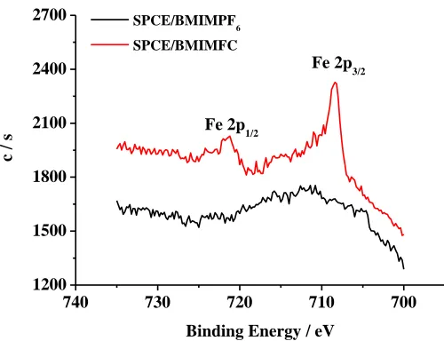
Figure 1. (A) UV-vis spectra of K3Fe(CN)6 (black line), BMIMPF6 (red line) and BMIMFC (green
line). (B) Narrow-scan XPS spectra of the Fe 2p regions acquired from SPCE/BMIMPF6 (black
line) and SPCE/BMIMFC (red line).
Synthesis of metal-containing ionic liquids has been reported in the literatures [29]. Accordingly, the anion exchange reaction to provide the corresponding iron-containing IL was conducted as follows.
One equivalent of colorless BMIMPF6 (1.0 mmol) in 3 mL acetonitrile and a half equivalent of
potassium ferricyanide (0.5 mL, 1.0 M) aqueous solution were mixed and stirred at room temperature for 24 h. The above mixture was left in the hood for several days to evaporate most of the solvent. In order to collect purified BMIMFC, de-ionized water was added several times to wash out the excess potassium ferricyanide. The resulting pale yellow ionic liquid was diluted in acetonitrile for characterization and further use. The successful anion exchange of hexafluorophosphate to ferricyanide was confirmed by the characteristic ferricyanide UV/Vis absorption peaks for BMIMFC appearing at 250-450 nm (Fig. 1A), and the XPS characteristic spectra for SPCE/BMIMFC modified electrode at 721 and 708 eV for Fe 2p1/2 and Fe 2p3/2, respectively (Fig. 1B)[33].
2.3. Instruments
Cyclic voltammetry was performed using a voltammetric analyzer (CH Instruments, model CH I-621C). A screen-printed carbon electrode (0.2 cm2) from Zensor R&D (Taiwan) was used as the working electrode, and was washed with de-ionized water before use. A platinum wire was used as the counter electrode. A home-made Ag|AgCl|KCl (sat.) electrode was used as the reference electrode. All potentials were reported with respect to this reference electrode.
[image:4.596.197.447.84.276.2]
(SEM) was used to characterize the electrode surface. The composition of the modified film was investigated using a PHI 5000 VersaProbe/PHI Quantera SXM (XPS/ESCA) instrument with an AlKX source.
2.4. Modified electrode preparations
The composite film-modified electrodes were obtained by a three-step strategy. First, 20 L of BMIMFC and 80 L of acetonitrile were mixed and stirred violently; 3 L of the mixture were deposited onto the SPCE, allowed to cover the whole electrode surface area, stood for 12 h in the air, and then spun at 3000 rpm for 5 min. The modified electrode was denoted as SPCE/BMIMFC. Secondly, 5 L of APTMOS and 400 L of methanol were mixed and stirred vigorously for 10 min; 1
L of the mixture (APTMOS sol) was completely deposited onto the previous electrode as the second modified layer, and kept in air for 5 min. The obtained electrode was denoted as SPCE/BMIMFC/SOL. The third step was to immerse the above electrodes in a 0.1 M HCl solution for 20 min, and a sol-gel network was achieved. The obtained electrode was denoted as SPCE/BMIMFC/SG. In the control experiments for the preparation of the mediatorless-modified electrode, BMIMPF6 was used instead of BMIMFC. All the modified electrodes were rinsed
thoroughly with distilled water, and stored in 0.1 M HCl solution until use.
3. RESULTS AND DISCUSSION
3.1. SEM characterization of the electrode surfaces
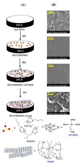
Figure 2A illustrates the three-step fabrication procedure of the composite film-modified electrode. The corresponding electrode surface morphologies (Fig. 2B) were investigated by SEM techniques to gain insights into the nature of the modified layers. The bare SPCE was characterized by a multi-layer surface where irregularly shaped graphite flakes dispersed homogeneously on the electrode. Upon spin-coating a thin layer of BMIMFC, the SEM images changed significantly. The SPCE/BMIMFC showed a very uniform, smooth surface topography with some bright tips. The plain structure indicated that BMIMFC filled the void spaces between the graphite flakes, and lead to the fine adherence of BMIMFC on the graphite electrode surface. This was consistent with the previous reports where smooth surface morphologies were observed for ILs-modified electrodes [26,30,40]. The report declared that ILs were embedded and bridged in the carbon layers and acted as ion carriers to transport charges between the carbon layers [30].
heterogeneous polymerization of pyrrole monomers, which adsorbed on the graphene oxide surfaces and was oxidized/ polymerized by ferric chloride solution [5].
[image:6.596.157.442.116.690.2](A) (B)
3.2. Electrochemical characteristicsof SPCE/BMIMFC
(A)
0.8 0.6 0.4 0.2 0.0 -0.2 -20
-15 -10 -5 0 5 10 15 20 25
I (b) (c) (d)
C
u
r
r
e
n
t
/
A
Potential / V vs. Ag/AgCl
(a)
II
[image:7.596.132.454.108.559.2](B)
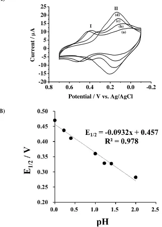
Figure 3. (A) Cyclic voltammorams of SPCE/BMIMFC in (a) 1, (b) 0.6, (c) 0.1 and (d) 0.01 M HCl solution. Scan rate = 0.1 V/s. (B) Plot of half-wave potential vs. pH for redox couple I.
The immobilized BMIMFC retained the original electrochemical activity of ferricyanide as indicated by the cyclic voltammograms (CV) in Fig. 3A. The results also revealed that more than one type of redox processes is involved. The redox couple I showed a half-wave potential (E1/2) at 0.47 V
in 1.0 M HCl (Epc = 0.42 V, Epa = 0.50 V), and this value was very close to the electrochemical redox
potentials of dissolved ferricyanide in strongly acidic solution [32]. The peak currents decreased and the peak potentials of redox couple I shifted negatively, while the redox couple II appeared gradually as the hydrochloric acid concentration decreased. The variations in E1/2 with solution pH values from
Nerstain slopes for a oneelectron redox process accompanied with one proton and two protons are -0.059 and -0.118 V/pH, respectively.
(A) (B)
0.6 0.4 0.2
-300 -200 -100 0 100 200 300
0.01 V/s
C
u
r
r
e
n
t
/
A
Potential / V vs. Ag/AgCl 1.5 V/s
[image:8.596.71.517.134.412.2](C) (D)
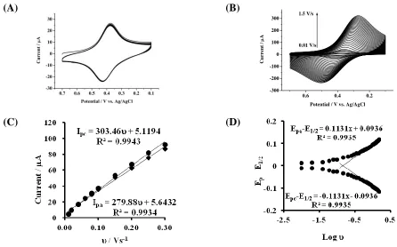
Figure 4. Cyclic voltammpgrams of SPCE/BMIMFC/SG in 0.1 M HCl (A) for continuous 50 cycles at a scan rate of 0.1 V/s. (B) at various scan rates () ranging from 0.01 to 1.50 V/s. (C) plot of peak current vs. scan rates () from 0.01 to 0.30 V/s. (D) plot of peak potential vs. log.
The obtained slope was in between the two values, suggesting the formation of mono- and di-protonated ferrouscyanide as the reduction products. In buffer solutions of pH values higher than 2.0, the redox couple I disappeared completely and only the redox couple II remained. The E1/2 of redox
couple II occurred at 0.20 V, and is independent of solution pH values. The redox potentials are consistent with the dissolved ferricyanide in KCl electrolytes [32] and the adsorbed ferricyanide in phosphate buffer solution (pH 7) [31]. That is to say, the redox couple II was ascribed to the redox process of Fe(CN)63-/Fe(CN)64-. Accordingly, the redox reactions of the adsorbed BMIMFC can be
written as Eq. 1.
FeIII(CN)63- + e- + x H+ HxFeII(CN)6-4+x (x = 0 ~ 2) (1)
ferrouscyanide, and they were detached from the film and leaked into the aqueous solution. The presence of poly-APTMOS sol-gel film as the outer layer actually showed effective improvement of the redox cycling stability. Fig. 4 A displayed the consecutive cyclic voltammograms obtained at SPCE/BMIMFC/SG in 0.1 M HCl, and the redox couple remained unchanged for at least 50 potential cycles. It is conceivable that the presence of cationic –NH3+ in the structure of poly-APTMOS sol-gel
film is responsible for the stabilization of the anionic reduction product.
As shown in Fig. 4B, the peak currents increased with the increase in the cyclic voltammetric scan rates () ranging from 0.01 to 1.5 V/s. Both the cathodic and anodic peak currents (Ipc and Ipa)
were proportional to the scan rate (0.01-0.3 V/s), giving linear regression equations for the cathodic and anodic peaks, respectively (Fig. 4C, Ipc (A) = 5.12 + 303.46v (Vs-1) and Ipa (A) = 5.64 + 279.88v
(Vs-1)). The electrochemical characteristics of the adsorption-controlled reaction confirmed the fact that the redox waves originated from the surface-bound ferricyanide. The surface coverage, ie., the amount of ferricyanide on the electrode surface, was estimated based on the integral charge of the reduction CV peak [23]. The calculated value was 4.3×10⁻⁹ mol/cm2, which indicated that multi-layers of BMIMFC participated in the electron-transfer reactions. The electron-transfer kinetics for the surface-bound ferricyanide was further analyzed. The electron-transfer coefficient () and the apparent heterogeneous electron-transfer rate constant (ks) were calculated by measuring the variations of peak potential with higher scan rates (Fig. 4D), based on Laviron’s theory [42]. The transfer coefficients were estimated to be 0.52 and 0.48 from the slope of the straight line for the cathodic and anodic reactions, respectively. The average value of ks was calculated as 3.14 s-1, which is expected fast enough for the immobilized ferricyanide to behave as a mediator to shuttle electron between electrodes and analyte molecules [20,24,40].
3.3. Electrocatalytic reduction of nitrite at SPCE/BMIMFC/SG
Figure 5 shows the voltammetric responses of three electrodes in 0.1 M HCl containing 1.0 mM NaNO2. There were no obvious electrochemical responses at bare SPCE (curve a) and
mediatorless-modified electrode (SPCE/BMIMPF6/SG, curve b), but a large cathodic response was
observed at SPCE/BMIMFC/SG (curve c). The CV of SPCE/BMIMFC/SG in the absence of NaNO2
has been shown for comparison (curve c’), where a redox couple of Fe(III)/Fe(II) was observed. Therefore, the enhanced responses at SPCE/BMIMFC/SG in the presence of NaNO2 reflected an
electrocatalytic reaction expected for a typical EC mechanism.
In order to test the effects of dissolved oxygen on the reduction wave, the 1.0 mM NaNO2
electrocatalytic reduction process was coupled with proton consumption. The reaction products were not further determined, and might include nitric oxide, hydroxylamine, hydrazine and ammonia depending on the number of electron transfer during electrolyses [10-16].
0.7 0.6 0.5 0.4 0.3 0.2 0.1
-3 -2 -1 0 1 2 3 4 5 6
(c)
(c') (b)
(a)
C
u
r
r
e
n
t
/
A
Potential / V vs. Ag/AgCl
Figure 5. Cyclic voltammorams of (a) bare SPCE, (b) SPCE/BMIMPF6/SG and (c)
SPCE/BMIMFC/SG in 0.1 M HCl containing 1.0 mM NaNO2. (c’) Cyclic voltammorams of
SPCE/BMIMFC/SG in 0.1 M HCl without nitrite. Scan rate = 0.01 V/s
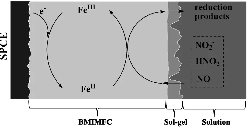
Scheme 1. The electrocatalytic reduction of NaNO2 at SPCE/BMIMFC/SG in 0.1 M HCl (figure is not
to scale).
[image:10.596.104.505.453.663.2]
turn, irreversibly reduced the nitrite to generate reduction products. Meanwhile, ferrouscyanide was oxidized back to ferricyanide, which gained electrons from the electrode surface for the next reaction cycles. In the solution layer, the nitrite anion was in equilibrium with nitrous acid (HNO2) in the highly
acidic conditions [11]. Nitric oxide (NO) and NO3- may co-exist due to the disproportionation reaction
of HNO2 [13]. The involvement of these nitrogen-containing species in the electrocatalytic reduction
reactions cannot be excluded, and more detailed studies are needed to reveal the reaction mechanisms.
3.4. Amperometric determination of nitrite
The determination of nitrite was performed by hydrodynamic amperometry in 0.1 and 1.0 M HCl solutions, respectively.
(A)
[image:11.596.134.459.287.687.2](B)
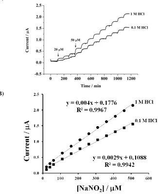
Figure 6. (A) Amperometric responses for the successive addition of NaNO2 at SPCE/BMIMFC/SG.
(B) Plot of current vs. NaNO2 concentration (20-510 M). Applied potential: 0.35 V vs.
Fig. 6A shows the typical plots of current vs. time with successive injections of NaNO2 into a
stirring solution at a potential of +0.35 V. The addition of nitrite in solution clearly resulted in the increase in the current responses at SPCE/BMIMFC/SG, whereas the same addition did not result in a recordable current response at the mediatorless-modified electrode (using BMIMPF6 instead of
BMIMFC).
(A)
0 400 800 1200 1600
0.0 0.5 1.0 1.5 2.0 d d d c c c b b a a a a a a C u r r e n t / A
Time / min
b
(B)
0 200 400 600 800 1000 1200 1400 1600
0.0 0.2 0.4 0.6 0.8 1.0 1.2 1.4 a a a g f e d c b a a C u r r e n t / A
Time / min
a
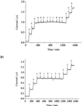
Figure 7. Amperometric responses in stirred 1.0 M HCl solution. Applied potential: 0.35 V. (A) Injection solutions: (a) 50 M NaNO2, (b) 1.0 M HCl (air-saturated), (c) 1.0 M HCl (pre-purged with O2 for 5 min), (d) 1.0 M HCl (pre-purged with O2 for 10 min). (B) Injection
solutions: (a) 50 M NaNO2, (b) 1 mM K2CO3, (c) 1 mM NH4Cl, (d) 1 mM MgSO4, (e) 1 mM
CaCl2, (f) 1 mM NaClO4, (g) 1 mM NaNO3.
0.0040 and 0.0029 A/M NO2- in 1 M HCl and 0.1 M HCl, respectively. The detection limit (S/N =3)
was 1.3 and 2.0 M NO2- for 1 M HCl and 0.1 M HCl, respectively. Usually, dissolved oxygen was
highly prone to interfere with the reduction of nitrite, especially in acidic solutions. Therefore, purging the detection system with a high-purity inert gas was necessary prior to experimental measurements [10,13-19]. In this study, the effects of dissolved oxygen and various salts on the analytical assays were studied. In Fig. 7A, the current given by 50 M nitrite solutions was achieved at the SPCE/BMIMFC/SG modified electrode. When air- or oxygen-saturated 0.1 M HCl solutions were added, no additional current was observed. The common ions, such as Na+, K+, NH4+, Ca2+, Mg2+, Cl-,
ClO4-, NO3-, SO42- and CO32-, in a 20-fold concentration had no considerable effect on the
determination of nitrite (Fig. 7B). However, Fe3+ and Sn2+ showed severe interference to the current response (data not shown).
Various types of electrocatalysts and biomolecules have been used to promote the electrochemical reduction of nitrite, and the comparisons are shown in Table 1.
Table 1. Comparison of the analytical performance for the electrocatalytic reduction of nitrite by amperometric methods.
Electrode Modifier Solution E,
(V vs. Ag/AgCl)
LOD, (μM)
Linear range, (μM)
Sensitivity (μA/M)
Reference
SPCE BMIMFC/SG 1M HCl 0.35 1.3 20-510 0.004 This work
GCE Poly(NiTRP)a 0.1M NaClO4 -0.80 9.37 14.9-1240 0.007 10
GCE PANI/PV-SO3
- /PSNP-NH2b
0.1 M HCl 0.05 7.4 up to 600 0.06 11
Au PANI/MWCNTc 0.1M H2SO4 0.00 1.0 5-15000 0.0002 12
GCE CuNPs/MWCNT/Nfd pH 2.0 -0.05 0.08 1-600 --- 13
GCE CuNPs/MWCNT/CSe pH 5.0 -0.20 0.024 0.1-2500 0.049 14
Au CuNPs/thiolf pH 2.0 -0.33 0.1 0.1-300 --- 15
GCE CNTs/Cu2+-DNAg pH 3.0 -0.30 0.03 0.03-2600 --- 16
GCE Hb/AuNPh pH 7.0 -0.85 0.065 0.4-14.8 --- 17
GCE Hb/AgNP/TiO2 SGu pH 4.5 -0.73 34.0 200-6000 0.0004 18
GCE Hb/CdSj pH 7.0 -0.85 0.08 0.3-182 --- 19
GCE Cat/MWCNTk pH 2.0 0.25 1.35 5-10000 0.007 20
PGE Cyt/PVAl pH 6.3 0.20 7.0 10-200 --- 21
[image:13.596.25.576.360.617.2]
The proposed assays showed an improved or comparable analytical performance for the values of detection limit and linear range. The low sensitivity is a common drawback for the nitrite sensors and biosensors using electrochemical reduction approaches. This disadvantage can be improved with the aid of multi-walled carbon nanotubes (MWCNT). The sensitivity can be enhanced 10 times when MWCNT were modified onto the electrode surface before BMIMFC modification (data not shown). Besides, the relatively positive potential gave optimal responses for nitrite and suppressed interference signals from dissolved oxygen. This property is benefit to the easy operation for field test.
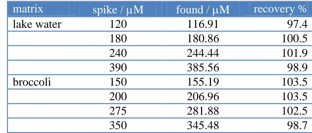
[image:14.596.135.453.363.499.2]Lake water and broccoli from the local area were selected as real samples for analysis using the standard addition technique. Lake water samples were filtered before use. Broccoli samples (60.0 g) were crushed adequately in the mortar. The broccoli extraction (250 mL) was achieved by mixing with hot de-ionized water (70 0C) under stirring for 15 min and further filtering of the solid mixture. The analytical results are summarized in Table 2. The recovery of the spiked samples ranged between 97.4% and 103.5%, showing that the proposed method could be effectively used for the determination of nitrite in real samples.
Table 2. Results of the recovery tests for nitrite in the real samplesa.
matrix spike / M found / M recovery %
lake water 120 116.91 97.4
180 180.86 100.5
240 244.44 101.9
390 385.56 98.9
broccoli 150 155.19 103.5
200 206.96 103.5
275 281.88 102.5
350 345.48 98.7
a. Nitrite contents were not found for the real samples.
4. CONCLUSIONS
ACKNOWLEDGEMENTS
The authors gratefully acknowledge the support provided by the National Science Council of the Republic of China under Grant NSC 98-2113-M-260-002-MY3. We would like to thank Prof. I-Wen Sun for his kind support with ionic liquid at the beginning of this study.
References
1. M. J. Moorcroft, J. Davis, R. G. Compton, Talanta 54 (2001) 785.
2. B. R. Kozub, N. V. Rees, R. G. Compton, Sens. Actuators B 143 (2010) 539. 3. B. R. Sljuki, R. O. Kadara, C. E. Banks, Anal. Methods 3 (2011) 105.
4. W. J.R. Santos, P R. Lima, A A. Tanaka, S M.C.N. Tanaka, L T. Kubota, Food Chem. 113 (2009) 1206.
5. D. Ye, L. Luo, Y. Ding, Q. Chen, X. Liu, Analyst, 136 (2011) 4563. 6. Y. Li, P. Wang, L. Wang, X. Lin, Biosen. Bioelectro. 22 (2007) 3120.
7. L. Jiang, R. Wang, X. Li, L. Jiang, G. Lu, Electrochem. Commun. 7 (2005) 597. 8. P. Kalimuthu, S. A. John, Electrochem. Commun. 11 (2009) 1065.
9. X. Huang, Y. Li, Y Chen, Lun Wang, Sens. Actuators B 134 (2008) 780.
10. P. Dreyse, M. Isaacs, K. Calfumán, C. Cáceres, A. Aliaga, M. J. Aguirre, D. Villagra, Electrochim. Acta 56 (2011) 5230.
11. M. Muchindua, T. Waryoa, O. Arotiba, E. Kazimierska, A. Morrin, A. J. Killard, M. R. Smyth, N. Jahed, B. Kgarebe, P. G. L. Baker, E. I. Iwuoha, Electrochim. Acta 55 (2010) 4274.
12. M. Guo, J. Chen, J. Li, B. Tao, S. Yao , Anal. Chim. Acta 532 (2005) 71.
13. S. Yang, X. Zeng, X. Liu, W. Wei, S. Luo, Y. Liu, Y. Liu, J. Electroanal. Chem. 639 (2010) 181. 14. S. Yang, X. Liu, X. Zeng, B. Xia, J. Gu, S. Luo, N. Mai, W. Wei, Sens. Actuators B 145 (2010)
762.
15. W.-Y. Ko, W.-H. Chen, C.-Y. Cheng, K.-J. Lin, Sens. Actuators B 137 (2009) 437. 16. S. Yang, B. Xia, X. Zeng, S. Luo, W. Wei, X. Liu, Anal. Chim. Acta 667 (2010) 57. 17. J. Hong, Z. Dai,Sens. Actuators B 140 (2009) 222.
18. S. Zhao, K. Zhang, Y. Sun, C. Sun, Bioelectrochem. 69 (2006) 10.
19. Z. Dai, H. Bai, M. Hong, Y. Zhu, J. Bao, J. Shen, Biosen. Bioelectro. 23 (2008) 1869. 20. A. Salimi, A. Noorbakhsh, M. Ghadermarzi, Sens. Actuators B 123 (2007) 530.
21. A.S. Serra, S.R. Jorge, C.M. Silveira, J.J.G. Moura, E. Jubete, E. Ochoteco, G. Cabanero, H. Grande, M.G. Almeida, Anal. Chim. Acta 693 (2011) 41.
22. P. Sun, D. W. Armstrong, Anal. Chim. Acta 661 (2010) 1. 23. M. Opallo, A. Lesniewski, J. Electroanal. Chem. 656 (2011) 2.
24. M. J.A. Shiddiky, A. A. J. Torriero, Biosens. Bioelectro 26 (2011) 1775. 25. D. Wei, A. Ivaska, Anal. Chim. Acta 607 (2008) 126.
26. N. Maleki, A. Safavi, F. Tajabadi, Anal. Chem. 78 (2006) 3820.
27. A. Safavi, N. Maleki, O. Moradlou, F. Tajabadi, Anal. Biochem. 359 (2006) 224.
28. R. T. Kachoosangi, M. M. Musameh, I. Abu-Yousef, J. M. Yousef, S. M. Kanan, L. Xiao, S. G. Davies, A. Russell, R. G. Compton, Anal. Chem. 81 (2009) 435.
29. K. Wang, F. Jian, R. Zhuang, Dalton Trans., (2009) 4532.
30. H. Liu, P. He, Z. Li, C. Sun, L. Shi, Y. Liu, G. Zhu, J Li, Electrochem. Commun. 7 (2005) 1357. 31. L. Xiang, Z. Zhang, P. Yu, J. Zhang, L. Su, T. Ohsaka, L. Mao, Anal. Chem. 80 (2008) 6587. 32. R. Ojani, J.-B. Raoof, E. Zarei, Electrochim. Acta 52 (2006) 753.
33. Y.-S. Chi, S. Hwang, B.S. Lee, J. Kwak, I.S. Choi, S.C. Young, S.-g. Lee, Langmuir 21 (2005) 4268.
34. L. Zhang, Q. Zhang, J. Li, J. Electroanal. Chem. 603 (2007) 243.
Soc. 126 (2004) 480.
36. E. Rozniecka, G. Shul, J. Sirieix-Plenet, L. Gaillon, M. Opallo, Electrochem. Commun. 7 (2005) 299.
37. A. Lesniewski, J. Niedziolka, B. Palys, C. Rizzi, L. Gaillon, M. Opallo, Electrochem. Commun. 9 (2007) 2580.
38. A. Lesniewski, M. Jcnsson-Niedziolka, J. Niedziolka-Jcnsson, C. Rizzi, L. Gaillon, M. Opallo, Electranal. 21 (2009) 701.
39. K. Szot, A. Lesniewski, J. Niedziolka, M. Jonsson, C. Rizzi, L. Gaillon, F. Marken, J. Rogalski, M. Opallo, J. Electroanal. Chem. 623 (2008) 170.
40. Q.-L. Sheng, J.-B. Zheng, X.-D. Shang-Guan, W.-H. Lin,Y.-Y. Li, R.-X. Liu, Electrochim. Acta 55 (2010) 3185.
41. M. M. Collinson, Trends in Anal. Chem. 21 (2002) 30. 42. E. Laviron, J. Electroanal. Chem. 101 (1979) 19.