This is a repository copy of
Nonlinear damping based semi-active building isolation
system
.
White Rose Research Online URL for this paper:
http://eprints.whiterose.ac.uk/129332/
Version: Accepted Version
Article:
Ho, C., Zhu, Y., Lang, Z. et al. (3 more authors) (2018) Nonlinear damping based
semi-active building isolation system. Journal of Sound and Vibration, 424. pp. 302-317.
ISSN 0022-460X
https://doi.org/10.1016/j.jsv.2018.03.023
[email protected] https://eprints.whiterose.ac.uk/ Reuse
This article is distributed under the terms of the Creative Commons Attribution-NonCommercial-NoDerivs (CC BY-NC-ND) licence. This licence only allows you to download this work and share it with others as long as you credit the authors, but you can’t change the article in any way or use it commercially. More
information and the full terms of the licence here: https://creativecommons.org/licenses/
Takedown
If you consider content in White Rose Research Online to be in breach of UK law, please notify us by
Nonlinear damping based semi-active building isolation system
Carmen Ho1, Yunpeng Zhu1, Zi-Qiang Lang1*, Stephen A. Billings1, Masayuki Kohiyama2 and
Shizuka Wakayama2
1 Department of Automatic Control and Systems Engineering, Sheffield University, Sheffield, S1 3JD, U.K.
2 Department of System Design Engineering, Keio University, Hiyoshi, Japan.
Email: [email protected]
Abstract: Many buildings in Japan currently have a base-isolation system with a low stiffness that is designed
to shift the natural frequency of the building below the frequencies of the ground motion due to earthquakes.
However, the ground motion observed during the 2011 Tohoku earthquake contained strong long-period waves
that lasted for a record length of three minutes. To provide a novel and better solution against the long-period waves while maintaining the performance of the standard isolation range, the exploitation of the characteristics
of nonlinear damping is proposed in this paper. This is motivated by previous studies of the authors, which
have demonstrated that nonlinear damping can achieve desired performance over both low and high frequency regions and the optimal nonlinear damping force can be realized by closed loop controlled semi-active dampers.
Simulation results have shown strong vibration isolation performance on a building model with identified
parameters and have indicated that nonlinear damping can achieve low acceleration transmissibilities round the structural natural frequency as well as the higher ground motion frequencies that have been frequently
observed during most earthquakes in Japan. In addition, physical building model based laboratory experiments
are also conducted, The results demonstrate the advantages of the proposed nonlinear damping technologies over both traditional linear damping and more advanced Linear-Quadratic Gaussian (LQG) feedback control
which have been used in practice to address building isolation system design and implementation problems.
In comparison with the tuned-mass damper and other active control methods, the proposed solution offers a more pragmatic, low-cost, robust and effective alternative that can be readily installed into the base-isolation
system of most buildings.
Key words: Isolation system; Earthquake; Nonlinear damping; Acceleration transmissibilities; Experimental
studies
1. Introduction
Traditional building base-isolation systems are designed to shift the structural resonant frequencies to a
range that is well below the frequencies of ground motions during earthquakes [1, 2]. To ensure a significant
reduction of vibration transmitted to a building over the isolation range which covers the frequencies of the
estimated earthquake ground motions, low horizontal-stiffness bearings are fitted into the isolation layer of the building. The current building regulations in Japan place limits on the design response spectrum with respect
to the ground motion for a duration of up to sixty seconds. However, during the most severe earthquake in
Japanese records that occurred off the Pacific coast of Tohoku in 2011, strong ground motions with a very long period lasted for about three minutes. Although the current seismic protection systems performed
reasonably well during the Tohoku earthquake as described in [3], structural engineers are becoming more
of this unprecedented earthquake, greater emphasis has naturally been placed to the building response to these long-period waves in future seismic protection designs.
To reduce the building vibration, a wide range of active control techniques have been discussed in [4, 5]. In
all these cases, the controller, designed by various methods such as classical and optimal control, deliver control signals to the actuators that apply forces to the structure. One major drawback of active control in
structural protection is the large power consumption that leads to a high maintenance cost. Stability could be
a concern when energy is added to the system. In contrast, passive control designs do not draw any external power and do not affect the system stability. For example, a conventional passive solution is to introduce
damping into the isolation system to suppress the impact of the long-period waves.
However, the intrinsic properties of linear damping inevitably lead to a compromised performance over the higher frequencies which unfortunately overlap the frequency range of the ground motions observed during
most earthquakes in Japan [6]. Recently, the authors have exploited the special characteristics of nonlinear
damping [7, 8] to create a vibration isolation system that has low transmissibilities over both low and high
frequencies [9–11]. As buildings in Japan now require base-isolation systems that can reduce the effects of
ground motion with frequencies in the traditional isolation range, which is usually a frequency range over 2
times building major resonance frequency, as well as lower frequencies around the resonant regions (about
0.2–0.4 Hz in Japan), the introduction of nonlinear damping would be hugely beneficial.
This paper presents the realisation of nonlinear damping using valve-controlled semi-active dampers in a building base-isolation system to protect the building against lateral vibration caused by the long-period waves
while maintaining sufficient isolation over the higher frequency spectrum of most of the historical earthquakes
ground motions. Although applicable to other multi-storey buildings, the analysis and simulation results presented in this paper are based on the nine-storey Sosokan Building at Keio University. Currently, the
building is protected by an optimal control system implemented by semi-active dampers [12]. The solution
proposed in this paper offers an alternative method that only requires a software update without any hardware changes. In addition to the numerical model based simulation studies, the laboratory experimental studies on
a two storey physical building model are also conducted. The experimental results confirm the results of the
numerical simulation studies and demonstrate the advantages of the proposed nonlinear damping technologies over traditional linear damping as well as currently operating LQG feedback control.
The paper is arranged as follows. In Section III, control methods developed for electrorheological dampers
[13, 14] are applied to the semi-active dampers to realize the designed nonlinear damping function [15]. The closed-loop controlled semi-active dampers are then incorporated into the building model under a single-tone
sinusoidal ground excitation in Section IV. Comparisons between the transmissibility curves of a linearly and
nonlinearly damped base-isolation system confirm the theoretical advantages of nonlinear damping in a vibration control application. The simulation results of the proposed system are also shown against the current
control system operating in the Sosokan Building that is based on a LQG design. In Section V, the set-up of
the laboratory experiments is introduced. The experimental results and the advantages of nonlinear damping technologies over other techniques are discussed. Finally, conclusions are drawn in Section VI.
2. Semi-active Damping System for the Sosokan Building
2.1 The Sosokan Building and its model representation
Sosokan, a symbolic nine-storey tower located in the Yagami campus of Keio University, was completed in
2000. Its isolation layer under B2F, is composed of sixty-five laminated rubber bearings, one set of twelve passive hydraulic dampers and four semi-active dampers oriented horizontally in the east-west direction and
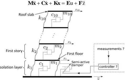
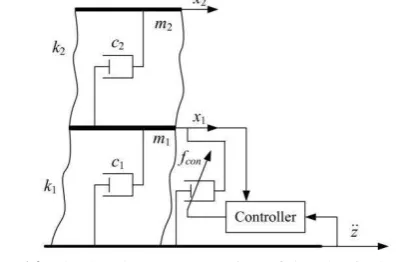
the horizontal ground acceleration as shown in Fig. 1 can be modelled by a system of mass-spring-damper in series given by
u z
Mx Cx Kx E F (1)
Isolation layer First story
[image:4.595.180.419.91.244.2]First floor Roof slab
Fig. 1. A model of a multi-storey building with built-in semi-active dampers in the isolation layer
where u represents the force of the semi-active damper,
T1, 2, 3, , 10
x x x x
x (2)
1 2 3 10
diag m m m, , , ,m
M (3)
1 2 2
2 2 3
9 10 10
10 10
0 0
0
0
0 0
c c c
c c c
c c c
c c
C (4)
1 2 2
2 2 3
9 10 10
10 10
0 0
0
0
0 0
k k k
k k k
k k k
k k
K (5)
T1, 0, 0, , 0
E (6)
and
T1, 2, 3, , 10
m m m m
F (7)
i
x for i1, 2, ,10 are the horizontal displacement of each floor relative to ground while m , i c and i k for i
1, 2, ,10
i are the mass, damping constant and spring stiffness respectively with values given in Tab.1.
Under the influence of the horizontal ground acceleration z , the performance of the base-isolation system
is determined by the total stiffness of the laminated rubber bearings k , the linear damping provided by the 1
passive dampers c1 and the force provided by all of the semi-active dampers u.
Assuming that the building is at a large distance from the epicenter, the ground input z can be modelled by
a sinusoidal signal given by
sin 2
zA ft (8)
where A and f are excitation magnitude and frequency in ms2 and Hz respectively [16]. The vibration isolation performance can then be measured by the ratio of the magnitude of the output spectrum evaluated at
F x t
i
z t
2 fT f
A
(9)
where F
. is the Fourier transform operation and x ti
, i1, 2, ,10 are the acceleration response of eachfloor of the building. With all system parameters held constants, T f
is dependent on the semi-active damperforce u. Their relationship will be further explored below.
Tab.1. Parameters of the Sosokan Building in the east-west direction [12]
Floor Mass 6
10 kg Stiffness 10 Nm 6 -1 Damping 10 Nsm 6 -1
B2F m14.9814 k1 66.836 c19.996
B1F m2 3.4382 k2 2273.6 c2 18.306
1F m3 2.4906 k3 2763.6 c322.252
2F m4 1.8264 k41979.6 c4 15.940
3F m5 2.0331 k5 1803.2 c5 14.520
4F m6 2.0500 k6 1813.0 c614.598
5F m7 2.0369 k7 1568.0 c7 12.625
6F m82.0371 k8 1381.8 c8 11.126
7F m9 2.0664 k9 1156.4 c9 9.3110
RF m102.4999 k10 999.60 c108.0487
2.2 Semi-active damping system for the Sosokan Building
Semi-active dampers are gaining popularity in vibration control as they could offer some benefits of active
control systems [17], without consuming a high level of energy or compromising the structural stability [18].
Controlled by electromagnetic valves which could move to several different positions, the semi-active dampers
is currently usedin the isolation layer of the Sosokan Building with an output force
l
u C v (10)
where vx1 and the linear damping coefficient can have four choices which are
1
1 3.33 MNsm
l p
C C ,
1
2 6.68 MNsm
p
C , Cp3
31.4 MNsm1
orCp4
58.8 MNsm1
. These linear relationships between the outputforce u and the velocity v are depicted in Fig. 2 (a). To alter the damping coefficient, an electronic signal is sent to the electromagnetic valves to modify their positions. The relationship between the actual values of the
damping coefficient Co
t and the electrical signal C ts
can be modelled by a first order system given by
1 1o
s
L C t
Ts L C t
(11)
where T0.1 s, an empirically-determined parameter based on tests of semi-active dampers and L
. is theLaplace operation.
Substituting Eqs. (8) and (10) into Eq. (1), the building model becomes a purely linear system when C is l
kept constant at one of the four values. The acceleration transmissibility curves from the ground input to the
isolation layer for different C are represented by the black lines in Fig. 3 with the effect of an increasing l Cl
indicated by blue arrows. The first mode of vibration occurs at about 0.25 Hz where a higher damping
long-period waves. On the contrary, when the frequency is higher, the transmissibility curve of the system where
4
l p
C C indicated by the black dash-dotted line is well above that of a system with Cl Cp1 indicated by the
black solid line. It is clear that none of a single semi-active damper setting could produce satisfactory isolation
[image:6.595.184.411.127.261.2]over the whole frequency range.
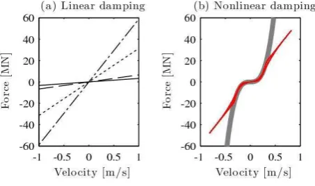
Fig. 2. Force-velocity relationship of semi-active damper.
(a) Four linear damping settings where u C vl , Cl Cp1 (solid), Cp2 (dashed), C (dotted) and p3 Cp4 (dot-dashed).
(b) Desired nonlinear damping (thick grey) where 3 n
u C v and that implemented by semi-active dampers under
closed-loop control (red solid)
If only one damper setting is chosen for each excitation frequency, the lowest possible transmissibility, referred
to as the optimal transmissibility line hereafter, can be achieved by selecting Cl Cp4 when f 0.35 Hz and
1
l p
C C when f 0.35 Hz, as shown in Fig. 3. Fig. 3 shows the transmissibility in both the linear and log
scale. In order to more clearly reveal the transmissibility over the whole range of frequency, the magnitude
will be presented in dB (10log10
T f
) in figures hereafter.Although it is not practical to implement an adaptive semi-active control system that switches between the
two damping coefficients purely depending on the excitation frequency, this optimal transmissibility line,
indicated by the thick pale blue line in Fig. 3 (b), sets a benchmark for other types of control methods based on this particular fluid viscous damper.
(a) The linear scale transmissibility (b) The DB scale transmissibility
Fig. 3. Acceleration transmissibility from ground input to the isolation layer where u C vl , Cl Cp1 (solid), Cp2
(dashed), C (dotted) and p3 Cp4 (dot-dashed). The optimal transmissibility line is notated by the thick pale blue line.
3. Nonlinear Damping Based Semi-active Building Vibration Isolation
The semi-active damper is considered as passive components that form an integral part of the system, where
[image:6.595.73.527.497.674.2]depending on signals from other parts of the building as illustrated in Fig. 4.
As discussed in [8], a nonlinear viscous damper has significant advantages over a conventional passive
viscous damper, especially in the high frequency region. The focus of this paper is to realize such a cubic
damping force in the base-isolation system of the Sosokan Building using controlled semi-active fluid viscous dampers as depicted in Fig. 4.
The idea of implementing a closed-loop controller to reshape the force-velocity relationship of a semi-active
damper was first developed for electrorheological dampers [13, 14]. This simple yet effective closed-loop control approach is now applied to the Sosokan Building aiming to transform the output force of the
semi-active dampers from four possible linear functions as shown in Fig. 2 (a) into a cubic function
3
d n
u C v (12)
as depicted by the thick grey line in Fig. 2 (b), where Cn is the cubic damping coefficient.
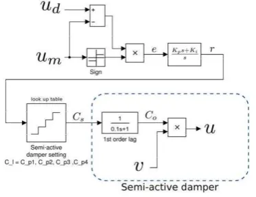
Fig. 4. Nonlinear damping implementation using semi-active dampers
The PI controller given by
0 d
t
p i
r t K e t K
e (13)is used to control the damping force to achieve the designed cubic damping characteristics in Eq. (12) where
sgn
m d m
e t u u u (14)
r t is the control signal of the same unit as Cp1,Cp2,Cp3,Cp4 and ud v (
1
MNsm ), um is the measured
damping force, and Kp and K are the proportional and integral gain (i sm1) of the PI controller, respectively. As the semi-active dampers are resistive devices, the sign adjustment in Eq. (14) is required to ensure that the output force is minimized when ud and u have opposite signs and the sign of m udum does not agree with
d
u . See [13] for more details.
Unlike electrorheological dampers, which accept a continuous current or a voltage signal, the fluid viscous
dampers in the Sosokan Building may only have one of four settings. The control signal r t
is thereforediscretized as
1 1 2
2 1 2 2 3
3 2 3 3 4
4 3 4
, for 2
, for 2 2
, for 2 2
, for 2
p p p
p p p p p
s
p p p p p
p p p
C r t C C
C C C r t C C
C t
C C C r t C C
C r t C C
(15)
Unlike any active design approach, the semi-active dampers remain as passive components during the design process. The closed-loop control method only requires local force and velocity measurements, which offers significant practical advantages over other control strategies that rely on feedback signals from sensors located on different floors of the building.
Fig. 5. Closed-loop semi-active damper control
4. Simulation Studies
A nonlinearly damped base-isolation system implemented by semi-active fluid viscous dampers as proposed
in Section III has been incorporated into the Sosokan Building modelled in MATLAB/Simulink.The results
are provided in Figs. 6–9.
4.1 Objectives of Nonlinear damping design
Sosokan Building, the vibration isolation performance is limited by the four available linear settings of the semi-active dampers. As discussed in Section II, the best possible isolation results when the building is under a single-tone sinusoidal excitation can be achieved by selecting Cl Cp4 in the low frequency range and
1
l p
C C in the high frequency range. This produces the optimal transmissibility line that the implementation
of nonlinear damping aims to achieve. For the purpose of comparison, this optimal line as well as the transmissibilities given by the semi-active damper at its highest damping setting Cl Cp4 is included in Figs.
6–9.
Fig. 6. Acceleration transmissibility from ground input
2
1 ms
A to the isolation layer where 3
n
u C v ,
9 3 3
0.588 10 Ns m
n
C (black solid),
9 3 3
2.94 10 Ns m
n
C (black dotted) are implemented by
[image:8.595.65.280.514.674.2]semi-active dampers and u C vp4 (red dotted).
Fig. 7. Acceleration transmissibility from ground input
2
2 ms
A to the isolation layer where 3
n
u C v ,
9 3 3
0.588 10 Ns m
n
C (black solid),
9 3 3
2.94 10 Ns m
n
C (black dotted) are implemented by
semi-active dampers and u C vp4 (red dotted).
[image:8.595.316.523.516.669.2]In Fig. 6, the system is excited by ground acceleration zAsin 2
ft
with 21 ms
A , the amplitude of
which is almost the same as the amplitude recorded in an actual earthquake [12].
Two values for nonlinear damping coefficients are chosen to show their effects on the isolation performance between the ground and the isolation layer. In order to enable the cubic damper to achieve the same
transmissibility as the linear damper with coefficient Cl Cp4 at the resonant frequency, the cubic damping
coefficient is designed as 9 3 3
0.588 10 Ns m
n
C to produce the nonlinear damping force 3
n
u C v . In this case, the system produces a transmissibility curve, shown by the black solid line, that is almost identical to the optimal transmissibility line indicated by the thick pale blue line. When the nonlinear damping coefficient is increased to a higher value such as 2.94 10 Ns m 9 3 3, a small increase in the acceleration transmissibilities around mid-frequency range from about 0.5 Hz to 3 Hz is observed. This implies an optimal solution to the
damping coefficient C can achieve the desired damping characteristics as indicated by the pale blue line in n
Figs. 6–9.
4.3 Effects of ground excitation magnitude
As the system contains nonlinear elements, the relationships between the ground input and the acceleration outputs are dependent on the excitation magnitude. Fig. 7 shows the transmissibility curves resulting from a larger input magnitude of A2 ms2. When the nonlinear damping coefficient is 0.588 10 Ns m 9 3 3, the transmissibility curve still lies very close to the optimal line. Even when Cn is raised to
9 3 3
2.94 10 Ns m , the
transmissibilities are well below the result generated with a linear system where Cl Cp4 over high
frequencies. Therefore, the optimal solution has a sufficient robustness with respect to the changes in loading
conditions. It is worth noting that the different magnitudes of 2
1 ms
A and 2
2 ms
A are two cases
recorded in an earthquake [12, 26], demonstrating the nonlinear damping based semi-active damper has a sufficient robustness with respect to the changes in loading conditions.
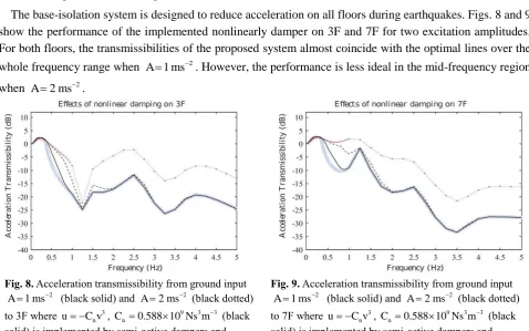
4.4 Isolation performance on higher floors
The base-isolation system is designed to reduce acceleration on all floors during earthquakes. Figs. 8 and 9 show the performance of the implemented nonlinearly damper on 3F and 7F for two excitation amplitudes. For both floors, the transmissibilities of the proposed system almost coincide with the optimal lines over the
whole frequency range when 2
1 ms
A . However, the performance is less ideal in the mid-frequency region
when 2
2 ms
A .
Fig. 8. Acceleration transmissibility from ground input
2
1 ms
A (black solid) and A2 ms2 (black dotted)
to 3F where 3
n
u C v , Cn0.588 10 Ns m 9 3 3 (black
solid) is implemented by semi-active dampers and
4 p
[image:9.595.58.537.432.731.2]u C v (red dotted).
Fig. 9. Acceleration transmissibility from ground input
2
1 ms
A (black solid) and A2 ms2 (black dotted)
to 7F where 3
n
u C v , Cn 0.588 10 Ns m 9 3 3 (black
solid) is implemented by semi-active dampers and
4 p
u C v (red dotted).
To resolve this issue, it is possible to design Cn for a specific range of A to achieve the optimal line over
4.5 Isolation performance in terms of the roof drift
The roof drift of the building is also an important criterion to assess the building isolation performance [20]. Denote the roof drift as
r
2f
R f F x t z t
(16)
where x tr
represents the displacement of the roof floor of the building, and z t is the ground displacement.
The roof drifts of the Sosokan Building in different cases were simulated and the results are shown in Fig. 10. The results indicate that when the same isolation performance at the resonant frequency is achieved, the
cubic damper 0.588 10 Ns m9 3 3
n
C can produce a better performance in terms of roof drift than a linear
damper with Cl Cp4 in both the cases of 2
1 ms
A and 2
2 ms A .
4.6 Isolation performance in terms of harmonics
The presence of harmonics is inevitable in a system containing any kinds of nonlinearities. The introduction
of cubic damping creates odd harmonics in the output signals. Using the concept of energy transmissibility to
include the effects of all super-harmonics in our previous study [11], it has been analytically shown that the
magnitudes of these harmonics are small compare to the size of the fundamental harmonic. Additionally, the
study has also shown that nonlinear damping can suppress the undesired harmonics and jumps caused by
stiffness nonlinearity. As the building itself may already contain some stiffness nonlinearities, the introduction of nonlinear damping would therefore enhance the overall system stability.
The simulation results in this section have demonstrated the advantages of a nonlinearly damped semi-active
base-isolation system. First, the acceleration transmissibilities achieved by the proposed system is very close to the optimal lines where only one damping coefficient can be chosen for each excitation frequency. Second,
although the performance of a nonlinear design is dependent on the input magnitude, the results have shown
sufficient robustness to the loading. Third, instead of optimizing the acceleration of one particular floor, the results indicate strong isolation performance across all floors.
Fig. 10. Roof drifts under the ground displacement amplitude
2
1 ms
A (black solid) and A2 ms2 (black dotted),
respectively when the nonlinear damping 3
n
u C v ,
9
0.588 10
n
C Ns m3 3 is implemented by the semi-active
dampers and when the linear damping u C vp4 (red dotted) is
[image:10.595.327.534.465.614.2]applied.
Fig. 11. Acceleration transmissibility from ground
input 2
1 ms
A to 3F, where the semi-active
dampers are controlled by the passive nonlinearly damping method (black solid) and the LQG method (red dashed).
Figure 11 shows a comparison of the acceleration transmissibility to 3F of the proposed nonlinear damped
system against the LQG design in[12]. It can be observed from Fig. 11 that the nonlinear damped system
delivers better performance over both the resonant higher frequency regions hence offers a more effective
[image:10.595.63.286.469.613.2]by minimizing the cost function provided by [12], the dampers often cannot deliver the designed optimal
performance in reality [21, 22]. Moreover, it is noticeable that the nonlinear damping design only relies on
local sensors in the isolation layer whereas any implementation based on an active control law (such as the
LQG approach) would require sensors on other floors. When considering the practical aspects of the design, the reliability and quality of the sensor communication, be it wired or wireless, must also be taken into account.
In order to confirm some important points reached by the numerical simulation, laboratory experimental
work has been conducted. The details are introduced in the next section.
5. Experimental Validation
To validate the performance of the proposed passive nonlinearly damped building isolation system, a scaled
physical model of the Sosokan Building has been built, as shown in Fig. 12, in a laboratory at Keio University.
The schematic of the semi-active damper in Fig. 13 shows two solenoid valves (with orifice diameters of 3 and 5 mm, respectively) which can be controlled to create four different damping coefficients that could
facilitate the implementation of the power law nonlinear damping.
Semi-active damper The first floor The second floor
Ground Shaker
[image:11.595.99.514.291.439.2]
Fig. 12. The laboratory physical model of Sosokan
Building Fig. 13. Schematic illustration of a semi-active damper
For base-isolated buildings, a 2-DOF model is often used to model the dynamic properties of a base-isolated
building [23, 24].
Fig. 14. The 2-DOF representation of the physical model
The equation of motion for the 2-DOF system in Fig. 14 can be described as follows.
con
f z
Mx Cx Kx E F (17)
where fcon represents the controlled damping force.
T1, 2
x x
x ; 1
2
0
0 m
m
M ; 1 2 2
2 2
c c c
c c
C ;
1 2 2
2 2
k k k
k k
[image:11.595.192.395.502.633.2]with
1 3.264 kg
m ; m21.589 kg; k1249.9 N m;
2 1968 N m
k ; c10.1294 Ns m and c2 1.019 Ns m
The first and second natural frequencies of the building model system are 1.134 Hz and 6.877 Hz, respectively.
A semi-active linear damper with the damping coefficient being able to be switched over four different values is fitted on the ground floor of the test rig, which is the same as the situation with the Sosokan Building.
The four damping coefficients are
1 30.8 Ns m; 2 40.1 Ns m; 3 44.5 Ns m; 4 84.8 Ns m
p p p p
C C C C (18)
The experiments were conducted when the sweep sine wave
20.6sin 2 m s
z t ft (19)
with f
0, 15 Hz
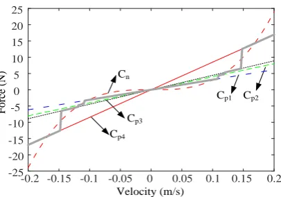
was applied as the loadings to the model.In the experiments, the cubic damping coefficient was chosen as 3 3
3000 Ns m
n
C . In this case, the cubic
damping characteristic and the force-velocity relationships of the semi-active damper under the four damping coefficients given in Eq. (18) are shown in Fig. 15 where the maximum velocity across the damper is 0.2 m s .
In order to compare the performance of the proposed nonlinearly damped system with the performance that can be achieved by the LQG based feedback control and traditional linear damping, an equivalent linear damping was chosen as Cp4 84.8 Ns m such that the three different techniques can achieve a similar
transmissibility over the resonant frequency range as shown in Fig. 15.
With respect to the LQG clipped semi-active control, the adopted cost functional is chosen following the
standard requirement in earthquake engineering [25]. The functional is the sum of squared floor accelerations
and squared control force with an empirically-tuned weight coefficient of 10 kg−2 as given by
2 2 2
0 1 0 2
0 d
J E x t x t x t x t Ru t t
(20)where E
. denotes the mathematical expectation, x t0
,x t and 1 x t are the accelerations on the ground, 2
the first, and the second floor, respectively, R10 kg2, and u t
is the semi-active control force.In (20), the term
0
1
2
0
2
2
0 d
E x t x t x t x t t
in the cost functional is introduced tominimise the absolute accelerations on each floor so as to reduce possible damage to contents and
non-structural components in a building structure. The additional term
2
0 d
E
Ru t t is used to penalise theexcessive control action that could take by the semi-active controller. The weighting value R10 kg2was
empirically tuned in order for the LQG clipped semi-active control to achieve the same transmissibility at the first resonant frequency as the transmissibility that can be achieved by the proposed cubic damping with
coefficient 3000 Ns m and its equivalent linear damping with coefficient 84.8 Ns m . This is to facilitate 3 3
an effective comparison between the three different building isolation techniques.
In determination of a Kalman filter gain, noise intensities are assigned 4 2 2
2.6 10 m s for system noise and
4 2 4
2.99 10 m s , 4 2 4
1.62 10 m s , and 4 2 4
Velocity (m/s)
F
orc
e (N
)
Cp4
Cp3
Cp2
Cp1
Cn
-0.2 -0.15 -0.1 -0.05 0 0.05 0.1 0.15 0.2 -25
-20 -15 -10 -5
[image:13.595.196.399.55.197.2] [image:13.595.174.447.280.370.2]0 5 10 15 20 25
Fig. 15. Force-velocity relationship of 3000 Ns m3 3
n
C and the real damping force (thick grey line)
In the laboratory studies, due to the limitation of the software system and also for the simplicity of implementation, instead of using the PI control in Eq. (15), a straightforward look-up table-based feedforward control was applied to determine the damping coefficient from its four available choices based on the measured velocity across the damper as follows:
1 1 2
2 1 2 2 3
3 2 3 3 4
4 3 4
, for 2
, for 2 2
, for 2 2
, for 2
p d p p
p p p d p p
s
p p p d p p
p d p p
C u v C C
C C C u v C C
C t
C C C u v C C
C u v C C
(21)
um C t vs
(22)where u and d u are the desired and measured damping force, respectively, and m v is the velocity across the
damper. In the experiments, v is estimated by a Kalman filter using the measured acceleration data z x and , 1
2
x . The implemented cubic damping characteristic is shown by the grey line in Fig. 15. Consequently, a
qualitative demonstration of the performance of the proposed nonlinearly damped system is expected from the experimental studies.
Remark: Eq. (15) shows how a PI feedback control can be implemented by using the semi-active damping
system currently used in the Sosokan Building to achieve a desired damping characteristic. Eq. (21) shows a simpler feed forward control solution used in the experimental study. Both implementations are based on traditional control system designs. Generally speaking, Eq. (15) is an ideal solution if the implementation is not constrained by hardware and software limitations. This is because a PI based close loop control can achieve the desired damping force better than an open loop method.
[image:13.595.91.522.555.700.2]
(a) The transmissibility of the 1st floor (b) The transmissibility of the 2nd floor
Fig. 16. Comparison of the transmissibilities: Cubic damper (Blue dot line); LQG (Red line); Linear damper (Green
dash line); No damper (Purple dash-dot line)
method; while the transmissibility with the equivalent linear damping increases significantly beyond the resonant frequency range of the system. All of these are consistent with the conclusions reached in Section IV from simulation studies.
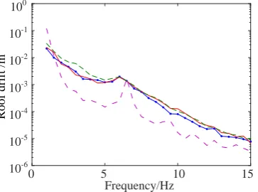
The roof drifts of the 2DOF physical building model controlled by the three different methods are shown in Fig.17, which further confirms the conclusion reached by simulation that the nonlinear damping method outperforms the other two approaches.
Roof dri
ft
/
m
0 5 10 15
Frequency/Hz 10-6 10-5 10-4 10-3 10-2 10-1 100
Fig. 17. Comparison of the roof drifts: Cubic damper (Blue dot line); LQG (Red line); Linear damper (Green dash line);
No damper (Purple dash-dot line)
In order to explain the superior performance of nonlinear damping over LQG, the situations with switching over the four different damping coefficients under the nonlinear damping and LQG are shown in Figs. 18 and 19 for the cases when the system is working at the resonant frequency ( f 1.0 Hz) and high frequency
(f 13 Hz), respectively.
D am pi ng c oe ffi ci ent s N s/ m D am pi ng c oe ffi ci ent s N s/ m
0 5 10 15
Time /s 30 40 50 60 70 80 90
0 5 10 15
Time /s 30 40 50 60 70 80 90
(a) Cubic damping (b) LQG
Fig. 18. Situations with switching over four damping coefficients at f 1.0 Hz
0 5 10 15
Time /s 30 40 50 60 70 80 90 D am pi ng c oe ffi ci ent s N s/ m
0 5 10 15
Time /s 30 40 50 60 70 80 90 D am pi ng c oe ffi ci ent s N s/ m
[image:14.595.209.391.143.278.2](a) Cubic damping (b) LQG
Fig. 19. Situations with switching over four damping coefficients at f 13.0 Hz
From Figs. 18 and 19, it can be observed that over the resonant frequency range, the nonlinear damping
approach select, the maximum damping coefficient for most of the time while the LQG method only
occasionally use the maximum damping coefficient. On the other hand, over the higher frequency, the nonlinear damping method uses smaller damping coefficients while LQG still opts for the maximum damping
[image:14.595.151.458.378.674.2]It is worth noting that the minimum damping coefficient that both nonlinear damping and LQG approach
can use in the experiment is Cp130.8 Ns m. If the minimum realisable damping coefficient is very small, it
is expected that the nonlinear damping would achieve almost the same transmissibility as that shown in purple
dash-dot line in Fig. 16 over the range of higher frequencies while still suppressing the vibration well over the resonance, showing an ideal performance over almost all ranges of frequencies.
6. Conclusions
In March 2011, the most powerful earthquake ever recorded in Japan occurred approximately 70 kilometres
east of the Oshika Peninsula. The measured ground motion contained long-period waves with unprecedented intensity and duration. However, the building regulations in Japan currently do not cover the profile of the
long-period waves observed in 2011. Engineers are therefore motivated to improve the current seismic
protection technologies.
Ideally, dampers used for system isolation should have high damping coefficients when the excitation
frequency is low and have low damping coefficients when the excitation frequency is high. As it is impossible
to predict the frequency spectrum of future earthquakes, changing dampers according to the input frequency is not a practical solution.
The authors have recently explored the idea of applying nonlinear damping to vibration isolation problems.
It has been proven that nonlinear damping in a vibration isolation system can offer sufficient isolation around the resonance without affecting the high frequency performance. In this paper, the realization of the desired
nonlinear damping force has been implemented using a semi-active damper, which can be readily achieved in
practice. The Sosokan Building model based numerical simulation studies and experimental studies on a scaled physical model have demonstrated the performance of the new technique and the advantages of the technique
over traditional solutions
The proposed nonlinear damping isolation system provides a good isolation against long-period waves as well as ground motions in the frequency spectrum which have been observed during most earthquakes. The
controller only requires force and velocity measurements that are local to the semi-active dampers. This is a
major practical advantage over other solutions as local measurements are much less susceptible to noise and interference. Instead of treating the semi-active dampers as actuators during the design process, the proposed
approach guarantees robustness and stability, which is essential during earthquakes.
Other advantages of the proposed method can be highlighted by comparing with some existing solutions. The nonlinear damping based semi-active dampers can be easily installed in the isolation layer of most
buildings without requiring a major redesign. Active actuators can be readily installed but the requirement of
a large power supply may have more safety implications. Therefore, in terms of costs, practicality and performance, the proposed nonlinearly damping solution is a better all-round alternative.
In the present study, the great potential of a base-isolation system with nonlinear damping implemented by
using a semi-active damper has been demonstrated when the ground motion can be assumed to be a
single-tone sinusoidal wave, which is often the case when the building is located far away from the epicenter.The
scenarios considered in this study are the earthquake ground motions which have either dominant frequency
in the isolated range or a dominant frequency in the non-isolated range of the system. The results indicate the proposed nonlinear damping solution guarantees that the base isolation system works well in both cases. For
the cases of near-fault ground motions as well as the cases where the ground motion contains energy in both
frequency ranges, the proposed cubic damping solution is also expected to perform better than linear solutions
[28]. However, a more comprehensive principle needs to be followed to perform the nonlinear damping design, which will be investigated and reported in a future publication.
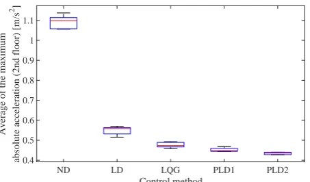
Fig. 20. An experimental comparison of the base isolation performances when the building model (Fig.12) is
subject to a simulated near-fault ground motion in the four cases of (i) No Damping (ND), (ii) Linear
Damping (LD), (iii) LQG, (iv) Two different cubic damping (denoted as PLD1 and PLD2, respectively)
Acknowledgment
The authors would like to thank the Engineering and Physical Sciences Research Council (EPSRC), UK and the European Research Council. The authors also acknowledge Mr. Maki Dan, Mr. Masahi Omura and Mr. Fumito Nakamichi at Keio University for their supports in the shaking table experiments.
References
[1] F. Naeim, The seismic design handbook, Springer Science & Business Media, 1989.
[2] A. Y. Fallah, T. Taghikhany, Sliding mode fault detection and fault-tolerant control of smart dampers in semi-active
control of building structures, Smart Mater. Struct. 24 (2015) 125030.
[3] K. Kasai, A. Mita, H. Kitamura, K. Matsuda, T. A. Morgan and A. W. Taylor, Performance of seismic protection
technologies during the 2011 tohoku-oki earthquake, Earthq. Spectra. 29 (2013) S265-S293. [Online] Available: http://dx.doi.org/10.1193/1.4000131.
[4] T. Soong, Active structural control: theory and practice, ser. Longman structural engineering & structural
mechanics series. Addison-Wesley, London. 1990.
[5] F. Amini, S. A. Mohajeri, M. Javanbakht, Semi-active control of isolated and damaged structures using online
damage detection,Smart Mater. Struct.24 (2015) 105002.
[6] P. Thureau, D. Lecler, J. Grosjean, An introduction to the principles of vibrations of linear systems, Thornes, 1981.
[7] B. Ravindra, A. K. Mallik, Chaotic response of a harmonically excited mass on an isolator with non-linear stiffness and damping characteristics, J. Sound Vibr. 182 (1995) 345-353.
[8] Z. Lang, X. Jing, S. Billings, G. Tomlinson, Z. Peng, Theoretical study of the effects of nonlinear viscous damping on vibration isolation of SDOF systems. J. Sound Vibr. 323 (2009) 352-365.
[9] C. Ho, Z. Q. Lang, B. Sapi´nski, S. A. Billings, Vibration isolation using nonlinear damping implemented by a feedback-controlled MR damper, Smart Mater. Struct. 22 (2013) 105010.
[10] C. Ho, Z. Q. Lang, S. A. Billings, Design of vibration isolators by exploiting the beneficial effects of stiffness and
damping nonlinearities, J. Sound Vibr. 333 (2014) 2489-2504.
[11] C. Ho, Z. Q. Lang, S. A. Billings, A frequency domain analysis of the effects of nonlinear damping on the duffing
equation, Mech. Syst. Signal Proc. 45 (2014) 49-67.
[12] M. Dan, M. Kohiyama, System identification and control improvement of a semi-active-controlled base-isolated
building using the records of the 2011 Great East Japan Earthquake, Safety, Reliability, Risk and Life-Cycle Performance of Structures and Infrastructures. (2014) 3841-3847.
[13] N. D. Sims, R. Stanway, D. J. Peel, W. A. Bullough, A. R. Johnson, Controllable viscous damping: an experimental
study of an electrorheological long-stroke damper under proportional feedback control, Smart Mater. Struct. 8 (1999) 601.
ND LD LQG PLD1 PLD2
Control method
0.4 0.5 0.6 0.7 0.8 0.9 1 1.1
A
v
er
ag
e
o
f
th
e
m
ax
im
u
m
ab
so
lu
te
a
cc
el
er
at
io
n
(
2
n
d
f
lo
o
r)
[
m
/s
[image:16.595.177.404.96.229.2][14] F. Blanchini, P. Colaneri, D. Casagrande, P. Gardonio, S. Miani, Switching gains for semi-active damping via
Nonconvex Lyapunov functions, IEEE Trans. Control Syst. Technol. 22 (2014) 721-728.
[15] S. A. Billings, Nonlinear system identification: NARMAX methods in the time, frequency, and spatio-temporal
domains, John Wiley & Sons. 2013.
[16] I. Takewaki, H. Tsujimoto, Scaling of design earthquake ground motions for tall buildings based on drift and input energy demands, Earthq. Struct. 2 (2011) 171-187.
[17] I. N. Kar, K. Seto, F. Doi, Multimode vibration control of a flexible structure using Hinfin-based robust control, IEEE-ASME Trans. Mechatron. 5 (2000) 23-31.
[18] D. Karnopp, Design principles for vibration control systems using semi-active dampers, J. Dyn. Syst. Meas. Control-Trans. ASME. 112 (1990) 448-455.
[19] Z. Q. Lang, S. A. Billings, R. Yue, J. Li, Output frequency response function of nonlinear Volterra systems, Automatica. 43 (2007) 805-816.
[20] E. Miranda, C. J. Reyes, Approximate lateral drift demands in multistory buildings with nonuniform stiffness, J.
Struct. Eng. 128 (2002) 840-849.
[21] M. Yu, X. M. Dong, S. B. Choi, C. R. Liao, Human simulated intelligent control of vehicle suspension system with
MR dampers, J. Sound Vibr. 319 (2009) 753-767.
[22] W. Q. Zhu, M. Luo, L. Dong, Semi-active control of wind excited building structures using MR/ER dampers, Probab.
Eng. Eng. Mech. 19 (2004) 279-285.
[23] K. Fujita, T. Miura, M. Tsuji, I. Takewaki, Experimental study on influence of hardening of isolator in multiple isolation building, Front. Built Environ. 2 (2016) 1-10.
[24] S. H. Eem, H. J. Jung, J. H. Koo, Seismic performance evaluation of an MR elastomer-based smart base isolation system using real-time hybrid simulation, Smart Mater. Struct. 22 (2013) 1-11.
[25] R. E. Christenson, B. F. Spencer Jr, N. Hori, K. Seto, Coupled building control using acceleration feedback, Comput.-Aided Civil Infrastruct. Eng., 18 (2003), 4-18.
[26] Z. Q. Lang, P. F. Guo, I. Takewaki, Output frequency response function based design of additional nonlinear viscous dampers for vibration control of multidegree-of-freedom systems, J. Sound Vibr. 332 (2013) 4461-4481.
[27] P. F. Guo, Damping System Designs using Nonlinear Frequency Analysis Approach Sheffield University. 2012
[28] M. Dan, O. Masashi, N. Fumito, K. Masayuki, Z. Q. Lang, Experimental study of the effectiveness of semi-actively implemented power-law damping on suppressing the seismic response of a base-isolated building, EACS 2016-6th