O R I G I N A L P A P E R
Open Access
GA-based multi-objective optimization of
active nonlinear quarter car suspension
system
—
PID and fuzzy logic control
Mahesh P. Nagarkar
1,2*, Yogesh J. Bhalerao
3, Gahininath J. Vikhe Patil
2and Rahul N. Zaware Patil
4Abstract
Background:The primary function of a suspension system is to isolate the vehicle body from road irregularities thus providing the ride comfort and to support the vehicle and provide stability. The suspension system has to perform conflicting requirements; hence, a passive suspension system is replaced by the active suspension system which can supply force to the system. Active suspension supplies energy to respond dynamically and achieve relative motion between body and wheel and thus improves the performance of suspension system.
Methods:This study presents modelling and control optimization of a nonlinear quarter car suspension system. A mathematical model of nonlinear quarter car is developed and simulated for control and optimization in Matlab/ Simulink® environment. Class C road is selected as input road condition with the vehicle traveling at 80 kmph. Active control of the suspension system is achieved using FLC and PID control actions. Instead of guessing and or trial and error method, genetic algorithm (GA)-based optimization algorithm is implemented to tune PID
parameters and FLC membership functions’range and scaling factors. The optimization function is modeled as a multi-objective problem comprising of frequency weighted RMS seat acceleration, Vibration dose value (VDV), RMS suspension space, and RMS tyre deflection. ISO 2631-1 standard is adopted to assess the ride and health criterion. Results:The nonlinear quarter model along with the controller is modeled and simulated and optimized in a Matlab/Simulink environment. It is observed that GA-optimized FLC gives better control as compared to PID and passive suspension system. Further simulations are validated on suspension system with seat and human model. Parameters under observation are frequency-weighted RMS head acceleration, VDV at the head, crest factor, and amplitude ratios at the head and upper torso (AR_h and AR_ut). Simulation results are presented in time and frequency domain.
Conclusion:Simulation results show that GA-based FLC and PID controller gives better ride comfort and health criterion by reducing RMS head acceleration, VDV at the head, CF, and AR_h and AR_ut over passive suspension system.
Keywords:Multi-objective optimization, Genetic algorithm, Nonlinear quarter car, PID, FLC
* Correspondence:[email protected]
1SCSM College of Engineering, Ahmednagar, MS 414005, India
2Research Department of Mechanical Engineering, AVCoE, Sangamner, MS,
India
Full list of author information is available at the end of the article
Background
The main function of an automotive suspension system is to support the vehicle weight, to isolate the occupants against the excitations caused by road unevenness and thus providing the ride comfort and better handling, and to keep the contact between tyre and ground. The task of the suspension system is a trade-off between ride and performance as ride comfort needs soft suspension sys-tem whereas to follow track and support vehicle weight stiff suspension system is required.
The primary objective of the active suspension system is to replace the passive suspension system by a controlled system which can supply force to the system. Active sus-pension supplies energy to respond dynamically and achieve relative motion between the body and the wheel. Thus, to changing road conditions, active suspension sys-tem improves the performance of the suspension syssys-tem such as ride comfort, suspension or rattle space displacement, tyre displacement, and body displacements (Wong2001). For active control, various control strategies are implemented like optimal control, robust control, non-linear control, nonnon-linear control with backstepping, sliding mode control, intelligent control, neural control, and hy-brid control. One of the main objectives was to minimize body acceleration to improve ride comfort.
Metered et al. (2015) had implemented particle swarm optimization (PSO) algorithm to tune the PID controller implemented on a semi-active quarter car suspension sys-tem. A 2DoF model with MR damper is simulated in a Matlab/Simulink environment with bump and random road inputs. The system was tested in time and frequency domain. It was observed that POS tuned PID controller improves ride comfort and vehicle stability. Kesarkar and Selvaganesan (2015) designed fractional order PID con-troller using artificial bee colony algorithm with objective functions such as integral absolute error, integral square error, and integral time absolute error implemented to a multi-modal complex optimization problem. The authors observed that the results were promising as compared to the conventional PID method. Niu (2014) had imple-mented GA-based optimization method to tune PID pa-rameters of the active suspension system. Absolute error control is used as an objective function to tune the PID parameters. It was observed that the GA-based optimized PID controller improves the dynamic performance of the active suspension system and improves stability. Gad et al. (2017) implemented a fractional order PID controller to a semi-active seat suspension. PID parameters are tuned using multi-objective GA for a seat suspension system using the 6-DoF human body. It is observed that GA-based PID controller improved SEAT value, VDV ra-tio, and crest factor as compared to the passive system and classical PID controller. Results are obtained in time as well as frequency domain. Tammam et al. (2013)
implemented a multi-objective GA-based PID controller to control the load frequency of a single area power sys-tem. It is observed that GA-based PID controller is simple and easy to implement and improves system performance effectively. Abdelrassoul et al. (2016) studied the perform-ance of the PV system based on GA-optimized PID con-troller. Here, PID controller is implemented to enhance PV system output with minimum overshoot and mini-mum rise time in output voltage with the better response. Chen and Chang (2006) studied GA-based PID tuning for active magnetic bearing. The proposed PID controller shows that the active magnetic bearing had good static and dynamic performance and showed better performance and effectiveness.
It is observed that optimization of PID controller applied to suspension system is carried out in single objective nature (Metered et al.2015; Niu2014) whereas (Kesarkar and Selvaganesan 2015) presented a multi-modal optimization approach and (Gad et al.
and Chao2000; Salem and Aly2009; Rajendiran and Lak-shmi 2016) have successfully implemented the FLC for ride control applications, whereas (Kalaivani et al. 2014) optimized FLC using a single optimization function.
Talib and Darus (2014) implemented a semi-active suspension system using FLC and PID controllers. Per-formance of both the controllers is optimized by the PSO algorithm for mean square error. Optimized FLC, PID controllers are compared with a passive suspension system for body displacement, acceleration, tyre dis-placement for bump, and hole disturbances. It is ob-served that the FLC controller gave better results as compared to the PID controller. Celin and Rajeswari (2012) implemented type-2 FLC to the active suspension system. Sprung mass displacement, RMS acceleration, suspension space, and tyre deflection criterions were used to study the FLC and passive suspension system. GA-coded FLC outperforms the FLC and passive sus-pension system. D’Amato and Viassolo (2000) presented the active suspension system to reduce the body acceler-ation to improve comfort. FLC is used to control where parameters are tuned by GA optimization. This method-ology improves ride comfort thus was effective in case of a quarter car suspension system. Li and Du (2006) pre-sented a GA-based approach to optimize rule base and scaling factors. The parameters were coded into real-coded strings and treated as chromosomes during optimization. The GA-based optimization approach im-proves the performance of FLC. Liu et al. (2016) had suc-cessfully optimized the membership functions of FLC to a maximum power point tracking (MPPT) algorithm using PSO algorithm to improve averaged tracking error and fit-ness value. Bouarroudj et al. (2017) had presented the comparative analysis of Mamdani FLC with Gaussian membership functions for MPPT of PV system using GA and PSO approach. It was observed that PSO and GA op-timized FLC gives better results in terms of performance.
This paper presents the mathematical modelling of a nonlinear quarter car (NLQC) along with a human model. The nonlinear quarter car model consists of quadratic tyre stiffness and cubic stiffness in suspension spring as non-linearities. PID and FLC are implemented with the control objective to minimize frequency weighted RMS sprung mass acceleration (hereafter called as RMS sprung mass acceleration), VDV, RMS suspension space requirement, and RMS tyre deflection along with RMS optimal control force. The constraints on optimization are maximum con-trol force, maximum sprung mass acceleration, maximum suspension space requirement, and maximum tyre deflec-tion. Due to multi-objective natures of optimal control and conflicting control objectives, the key issue is to select the PID gain values and range of fuzzy input and output membership functions and scaling factors to fulfill the conflicting requirements. Trial and error method and or
manual tuning of the PID controller and FLC are cumber-some and time-consuming. Hence, a GA-based evolution-ary optimization technique is used to search the optimum parameters. During optimization, a nonlinear optimal control system is simulated in a Matlab/Simulink® envir-onment where the tuning parameters are selected from the search space. The output of the nonlinear optimal control system is fed to the optimization algorithm to de-termine the objectives and validate the constraints. The optimization procedure is repeated up to 100 generations. Further, the optimization results are validated on a quarter car with seat and human model. Results are presented in both time domain and frequency domain.
Methods
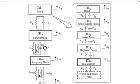
Mathematical modelling—nonlinear quarter car suspension-seat-human model
A suspension system consists of damper and coil springs. Researchers have used various mathematical models viz. quarter car model having 2-DoF, a half car model having 4-DoF, and full car model. In this study, a 2-DoF quarter-car model is implemented for ride and control applications (Metered et al.2015; Kalaivani et al.
2014; Taskin et al.2017; Huang and Chao (2000); Salem and Aly2009; Rajendiran and Lakshmi2016).
Mathematical modeling is carried out using linear springs and damper by various authors (Kalaivani et al.
2014; Taskin et al.2017; Huang and Chao (2000); Salem and Aly 2009; Rajendiran and Lakshmi 2016). But it is observed that spring exhibits nonlinear nature so do the tyre (Fuller et al.1996). Thus, the nonlinearity should be considered during modeling. McGee et al. (2005) studied nonlinearities in the suspension system using a fre-quency domain technique and are validated experimen-tally with shaker data. It was observed quadratic and cubic stiffness and Coulomb friction nonlinearities in the suspension system (McGee et al.2005). A chaotic re-sponse was presented by Zhu and Ishitobi (2006). They used a 7-DoF model with tyre stiffness and suspension spring stiffness nonlinearities. Bifurcation and chaotic response of 2-DoF model with tyre stiffness and suspen-sion spring stiffness nonlinearities were presented by Lixia and Wanxiang (2008).
In the present analysis, a nonlinear quarter car model having quadratic tyre stiffness and cubic stiffness in sus-pension spring nonlinearities are considered.
A human model suggested by (Boileau and Rakheja
According to D’Alembert’s principle, the governing equations of motion representing nonlinear quarter car suspension-seat-human model are represented as–
mus€xus¼−ktðxus−xrÞ þksðxs−xusÞ þcsðx_s−x_usÞ þktnlðxus−xrÞ2
þksnlðxs−xusÞ3−f
ms€xs¼−ksðxs−xusÞ−csðx_s−x_usÞ−ksnlðxs−xusÞ3þkf xf−xs
þcf x_f−x_s
þf
mf€xf¼−kf xf−xs
−cf x_f−x_s
þkc xc−xf
þcc x_c−x_f
mc€xc¼−kc xc−xf
−cc x_c−x_f
þktpðxt−xcÞ þctpðx_t−x_cÞ
mt€xt¼−ktpðxt−xcÞ−ctpðx_t−x_cÞ þkltðxlt−xtÞ þcltðx_lt−x_tÞ mlt€xlt¼−kltðxlt−xtÞ−cltðx_lt−x_tÞ þkutðxut−xltÞ þcutðx_ut−x_ltÞ mut€xut¼−kutðxut−xltÞ−cutðx_ut−x_ltÞ þkhðxh−xutÞ þchðx_h−x_utÞ mh€xh¼−khðxh−xutÞ−chðx_h−x_utÞ
g
ð1Þ
The nonlinear quarter car seat-suspension-human model parameters are as follows:
mh= 5.31;ch= 400;kh= 310,000;
mut= 28.49;cut= 4750;kh= 183,000;
mlt= 8.62;clt= 4585;klt= 162,800;
mt= 12.78;ct= 2064;kt= 90,000;
mc= 1;cc= 200;kc= 18,000;
mf= 15;cf= 830;kf= 31,000;
ms= 290;cs= 700;ks= 23,500;ksnl= 100ks(Lixia and Wanxiang2008);
mus= 40;kt= 190,000;ktnl= 1.5kt(Zhu and Ishitobi 2006).
The nonlinear quarter car having quadratic stiffness nonlinearity in the tyre and cubic stiffness in suspension spring is modeled and simulated in Matlab/Simulink®. Further, the simulations are carried out on a quarter car model with seat consisting frame and cushion with a hu-man model.
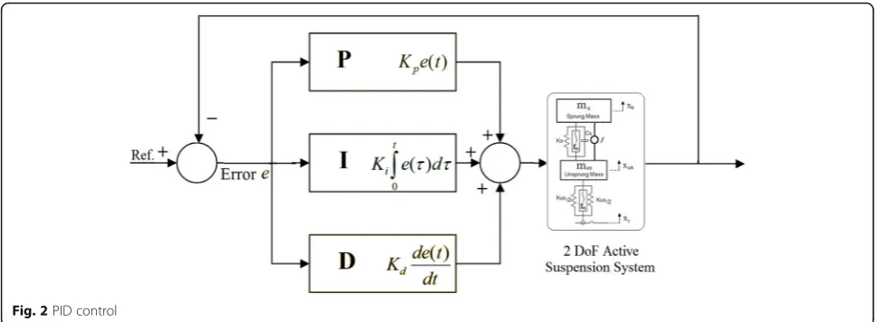
Control theory—PID control
PID stands for proportional, integral, and derivative and is a classical controller used for several control applica-tions (Metered et al. 2015; Kesarkar and Selvaganesan
2015; Niu2014; Gad et al. 2017; Tammam et al. 2013; Abdelrassoul et al. 2016; Chen and Chang 2006). The PID controllers are so designed that continuous atten-tion of the operator is eliminated. As the PID controller has designed a derivative nature type, small variation of output can be easily avoided. A PID controller is depicted in Fig. 2. The set point is where the
measurement should be. An error is defined as the dif-ference between the set pointr(t) and measurementy(t). PID computes the control signal based on the following equations:
u tð Þ ¼Kpe tð Þ þKi Z
e tð ÞdtþKd d
dte tð Þ ð2Þ
e tð Þ ¼r tð Þ−y tð Þ ð3Þ
The error, e(t), variable being adjusted is called the manipulated variable which usually is equal to the out-put of the controller. As there is a change in measure-ment or set point, so is the output of the controller. Generally, Z-N tuning or auto-tuning is used to tune the P, I and D parameters of the controller.
Control theory—fuzzy logic control
FLC uses heuristic information for control applications. The FLC uses rule-base derived through an operator’s experience and thus acts as a human-in-the-loop con-troller providing human experience to achieve high per-formance (Kalaivani et al. 2014; Taskin et al. 2017; Huang and Chao2000).
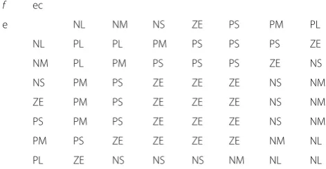
Figure3 represents the structure of a typical FLC im-plemented for a 2-DOF suspension system. Here, two in-puts (error e and ec) and one output (force fFLC) FLC with rule-base is implemented. Sprung mass velocity (error e) and acceleration (change in error ec) are used as input, and control force (fFLC) is output. FLC rule base is a linguistic-based rule base which incorporates past human experience. Table1 represents the rule base for two input-one output rule base for ride comfort. Fig-ure 4 represents the surface plot rule base as stated in Table1.
Fig. 2PID control
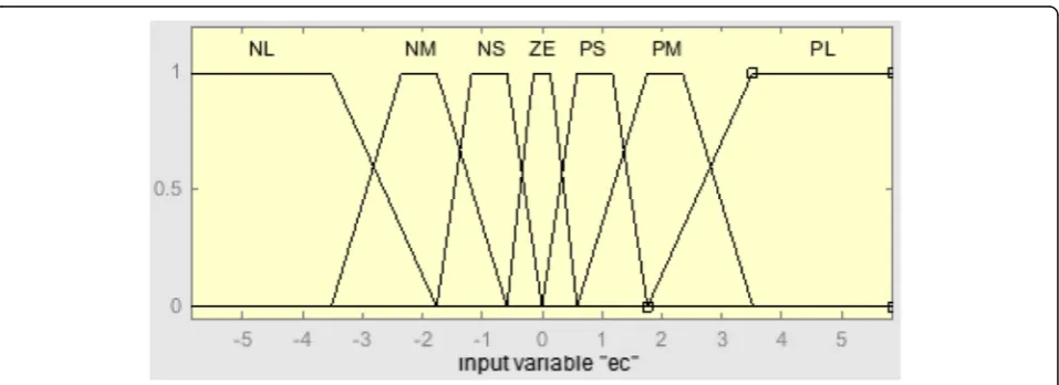
Firstly, FLC decomposes the input into fuzzy sets, called as fuzzification, using membership functions (MF). Primarily membership functions map practical space to fuzzy space, known as fuzzification. Here, trap-ezoidal membership functions are used for input and output variables (refer Figs. 5, 6, and 7). The FLC con-sists of seven membership functions each, ie., for two in-puts (error e and change in error ec) and an outputfFLC; these are NL, NM, NS, ZE, PS, PM, PL. Mamdani type fuzzy inference system (FIS) is used. Defuzzification is the process which maps the variables back to practical space from fuzzy space. Centroid defuzzification method is used in this FLC.
Objective functions
One of the key factors in optimization problems is to choose proper objective functions. Here, the control strategies are implemented to improve ride characterized
by RMS sprung mass acceleration, VDV, RMS suspen-sion space deflection, RMS tyre deflection, and RMS controller force.
RMS acceleration
As per ISO 2631-1 (1997), RMS acceleration is given by
Aws ¼ f
1 T
Z T
0
½awðtÞ2dtg 1 2
ð4Þ
A major portion of the vibration experienced by the occupants of an automobile enters the body through the seat (Van Niekerk et al.2003; Bovenzi 2005). The health risk increases as the exposure time to vibrations in-creases. Hence, is it necessary to measure the whole body vibrations for ride and health criterion. As per ISO 2631-1 (1997), VDV is one measure for whole body vi-brations. VDV also called as fourth power vibration dose. VDV is the method of assessing the cumulative ef-fect (dose) of the vibration.
Vibration dose value (VDV)
VDV is the fourth power of acceleration time histories. It is expressed as
-VDVs¼
Z T
0
awð Þt
½ 4dt
1
4
ð5Þ
Suspension travel
Suspension travel is characterized by the relative travel between the sprung mass and unsprung mass. Due to
Table 1Fuzzy logic rule table (2-DoF active suspension system)
f ec
e NL NM NS ZE PS PM PL
NL PL PL PM PS PS PS ZE
NM PL PM PS PS PS ZE NS
NS PM PS ZE ZE ZE NS NM
ZE PM PS ZE ZE ZE NS NM
PS PM PS ZE ZE ZE NS NM
PM PS ZE ZE ZE ZE NM NL
PL ZE NS NS NS NM NL NL
Nnegative,ZEzero,Ppositive,Llarge,Mmedium,Ssmall
random input, RMS suspension space travel is taken as one of the objective functions.
Suspension Travel¼xs−xus ð6Þ
RMS Suspension Travel¼ 1 T
Z T
0
xsð Þt −xusð Þt
ð Þ
½ 2dt
1
2
ð7Þ
Dynamic tyre deflection
Dynamic tyre force is related to tyre deflection. Due to the random nature of input, the RMS of tyre deflection is the next objective function.
Tyre Deflection¼xus−xr ð8Þ
RMS Tyre Deflection¼ 1 T
Z T
0 x
usð Þ−t xrð Þt
ð Þ
½ 2
dt
1
2
ð9Þ
Control force is introduced as one of the objective functions, to find optimum control force to achieve ride comfort.
RMSf ¼ 1
T
Z T
0 f t
ð Þ
ð Þ
½ 2
dt
1
2
ð10Þ
According to Baumal et al. (1998), at least, 125 mm of suspension travel is required, and maximum seat acceler-ation should not increase 4.5 m/s2to avoid hitting the sus-pension stop. To minimize dynamic tyre forces, maximum tyre deflection should not increase 0.0508 m. These parame-ters are included as constraints in the optimization problem.
Fig. 5Membership function (e)
The formulation of the optimization problem is as follows:
fob j1¼MinimizeðRMSfÞ
fobj2¼ Minimize VDVð sÞ
fobj3¼ Minimize Að wsÞ
fobj4¼ Minimize RMS Suspension Travelð Þ
fobj5¼ Minimize RMS Tyre Deflectionð Þ
Subject to constraints:
amax seat ≤4:5m
s2; Max:ðxs−xusÞ≤0:125m;
Max:ðxus−xrÞ≤0:0508m;fmax≤2000 N:
Multi-objective optimization
Researchers have invented several meta-heuristic optimization algorithms to optimize the problems in several fields. These algorithms have implemented on several mathematical problems involving single objective optimization to multi-objective optimization and pro-vided excellent results.
The suspension system has to perform several conflict-ing objectives such as ride comfort, road holdconflict-ing, and
suspension/rattle space requirements. Thus, the optimization problem becomes a multi-objective type (consisting of RMS control force, VDV, RMS sprung mass acceleration, RMS suspension space requirement, and RMS dynamic tyre deflection as objective functions) with conflicts. As compared to a single objective optimization problem, a multi-objective optimization (MOO) problem has to satisfy several objectives simul-taneously. Hence, multi-objective optimization using a genetic algorithm (GA) (Holland1992; Holland1975) is implemented to solve the optimization problem.
In the solution of MOO problems, MOO forms a Pareto optimal front consisting of multiple optimal solu-tions. GA is implemented to optimize in multiple do-mains as it handles complex optimization problems with discontinuities, non-differentials, noisy functions, and functions with multi-modality. GA also supports parallel computations with obtaining Pareto front in a single run. Non-dominated sort GA-II (NSGA-II) (Deb et al.
2002) is one of the MOEAs using GA strategy. NSGA-II implements non-dominated sort algorithm thus redu-cing the computational complexities. While sorting the parents and children, elitism is introduced in NSGA-II. In NSGA-II, to preserve the diversity and uniform spread of optimal front, a crowding distance (CD) (Deb et al. 2002) operator is used. Chromosomes with better fitness are assigned highest ranks, and thus, they deter-mine the domination.
From the non-dominated front, parents are selected by tournament selection and compared to the CD. New
Fig. 7Membership function (U)
Table 2Membership functions
MF Input 1 (e) Input 2 (ec) Output (f)
NL [−1–1−0.7−0.4] [−1−1−0.6−0.3] [−1−1−0.9−0.6]
NM [−0.7−0.5−0.3−0.05] [−0.6−0.4−0.3−0.1] [−0.9−0.7−0.5−0.2]
NS [−0.4−0.2−0.1 0] [−0.3−0.2−0.1 0] [−0.6−0.3−0.2 0]
ZE [−0.05−0.01 0.01 0.05] [−0.1−0.025 0.025 0.1] [−0.2−0.05 0.05 0.2]
PS [0 0.1 0.2 0.4] [0 0.1 0.2 0.3] [0 0.2 0.3 0.6]
PM [0.05 0.3 0.5 0.7] [0.1 0.3 0.4 0.6] [0.2 0.5 0.7 0.9]
PL [0.4 0.7 1 1] [0.3 0.6 1 1] [0.6 0.9 1 1]
Table 3Design variables range—PID Control
Design variable
Range Size
Kp 15,000–2000 = 13,000 213
= 8192 < 13,000 < 214
= 16,384 14 bits
Ki 150–10 = 140 27
= 128 < 140 < 28
= 256 08 bits
Kd 50,000–15,000 = 35,000 215
= 32,768 < 35,000 < 216
off-springs are created using a crossover operator and mutation operator. New off-springs and current tion (parents) are combined to generate a new popula-tion. Selection is carried out for next generation individuals. The binary tournament selection method is used by NSGA-II to handle constraints. For multi-objective optimization, NGPM code (NSGA-II
Program in Matlab) is used (Song 2011; Song 2015). NGPM is the implementation of NSGA-II (non-domi-nated sort genetic algorithm) in Matlab.
Optimization methodology—PID control
During simulation and optimization of PID controller, PID parameters are randomly initialized, and objective functions are determined. Then, optimum PID parame-ters are iteratively obtained till algorithm stops. The classical PID gains are determined using the Z-N method.
Search space for PID controller is as follows
-Kp∈½2000;15000;Ki∈½10;150;Kd∈½15000;50000:
Optimization methodology—fuzzy logic control
FLC is a typical two input-one output functions control-ler. In this design, initially, seven trapezoidal member-ship functions are defined for two inputs and output. The seven membership functions are initialized in the range of [−1 1] and are then multiplied using respective scale factors. Table 2 represents the initial membership functions in the range of [−1 1]. Also, error (e), change in error (ec) and control output (f ) are scaled using scal-ing factors ke, kec, and kf respectively and included in the Simulink® model.
During optimization, values are randomly initialized and the model is simulated to determine objective func-tions. Then, iteratively optimum parameters are obtained from their ranges till the algorithm stops.
The search space for the input-output functions and scaling factors is as follows:
Input Function1∈½1;10;Input Function2∈½1;10;
Output Function1∈½1;10
ke∈ −½ 5;5;kec∈ −½ 5;5;kf∈½0;25
NSGA-II—population range
In GA, the range of design variable Kp is (15000–2000=) 13,000. Thus, the design variable Kp needs to be divided into 13,000 equal range of size. Hence, 213= 8192 <
Fig. 8Flow chart—GA (Nagarkar et al.2016)
Table 4ISO Road classification (ISO 8608 (1995))
Road class Degree of roughnessϕ(no) (10− 6
m2/(cycle/m)) Where no= 0.1 cycle/m
Lower limit Geometric mean Upper limit
A (very good) – 16 32
B (good) 32 64 128
C (average) 128 256 512
D (poor) 512 1024 2048
13,000 < 214= 16,384, i.e., 14 bits are required to store the value of design variable Kp in the chromosome. Similarly, for other design variables, the bit required is tabulated in Table3.
Hence, the total length of chromosome or gene is 14 + 08 + 16 = 38 bits that are required, where the first 14 bits are required for Kp, the next 08 bits are required for Ki, and the next 16 bits are required for Kd. Popula-tion size is selected such that
Ns< population size < 2Ns, where Ns= string length (Alander1992)
Also, the range of variables for the FLC design variables is small as compare to the PID controller. Thus, selecting population size of 100 (Rosenthal and Borschbach 2014; Hernández-Díaz et al. 2008; Nagarkar et al. 2016) and optimization is stopped after 100 generations. Figure8 ex-plains the flowchart of the GA algorithm implemented for multi-objective optimization.
Fig. 9Road surface (class C, velocity 80 kmph)
Results and discussion
Multi-objective optimization of the non-linear quarter-car model is simulated in a Matlab/Simulink® environment using NSGA-II algorithm.
The stationary road roughness is effectively described by power spectral density (PSD). When a car moves at a constant velocityv, the road roughness can be viewed as a stationary process in the space domain. The differen-tial equation of road roughness can be expressed as (He et al.2008; Zhang et al.2007):
_
xrð Þ þt 2πnovxrð Þ ¼t
ffiffiffiffiffiffiffiffiffiffiffiffiffiffiffi Sqð Þno v q
w tð Þ ð11Þ
Equation (11) is modeled in the Simulink environment to model the road surface. According to ISO 8608, roads are divided into classes like A, B, C, D, and E. Class A and B represents expressways or motorways, whereas class C road is a typical average road type. Class B and C roads are generally country or district roads. Class C road considers velocities of typical secondary roads ran-ging from ~ 30 kmph to ~ 60 kmph. The input road condition is modeled as class C road (average road) with a degree of road roughness 512 × 10−6 m2/(cycle/m) (Zhang et al.2007; ISO 86081995). Refer to Table4for the road roughness classification. The vehicle is traveling with a velocity of 80 kmph. Figure9represents the class C road surface.
PID controller
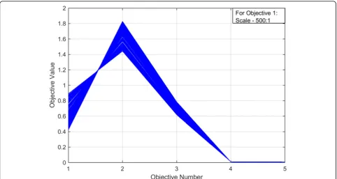
The trade-off front of 100 different solutions for object-ive functions satisfying the constraints is obtained after optimization. The trade-off front is shown in Fig.10. For ride comfort and health criterion, RMS acceleration and VDV are selected as optimum values. Hence, for PID controller P, D and D parameters’ gain values are se-lected for minimum valued of RMS acceleration and VDV and simulated further. Refer to Table7for the cor-responding optimized PID parameters.
It is observed that the RMS acceleration for the GA-optimized PID controller is 0.6178 m/s2, which is a little uncomfortable. In GA-PID controlled system, RMS
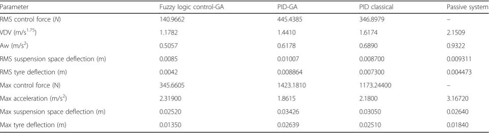
acceleration is reduced by 34% (passive suspension sys-tem has RMS acceleration 0.9322 m/s2which is uncom-fortable) and is reduced by 10% as compared to the classical PID control. For GA optimized PID controller, VDV is reduced by 33% as compared to the passive sus-pension system and is reduced by 11% as compared to classical PID control. Also, constraints are not violated in the GA optimized system. The results of RMS optimal control force, RMS sprung mass acceleration, RMS sus-pension space, RMS tyre deflection, maximum controller force, and maximum sprung mass acceleration are tabu-lated in Table 5 (refer to Fig. 11 for time domain results).
Further frequency domain analysis is carried out for the PID controlled system and passive system. In fre-quency analysis, it is observed that the optimized PID controlled system experiences low amplitudes of body accelerations as compared to the passive suspension sys-tem (refer to Fig. 12). PID can reduce the amplitude of body accelerations at points 100and 101Hz frequencies. Also, it shows better performance over higher amplitude regions > 10 Hz.
Fuzzy logic control
During simulation 2-DOF nonlinear active suspension system, it is excited by a random road disturbance. The NSGA-II-based optimization is carried out and results are obtained using a MATLAB/SIMULINK. The velocity and acceleration of sprung mass are selected as an error (e) and change in error (ec) feedback signals for the 2-DOF suspension system control.
The trade-off front of 100 different solutions for ob-jective functions satisfying the constraints is obtained after optimization. The trade-off front is shown in Fig.13. For ride comfort and health criterion, the mini-mum RMS acceleration and VDV are selected as optimum values. Hence, FLC parameters, ke, kc, kf, and scaling factors for input-output membership functions are selected having minimum values of RMS acceler-ation and VDV corresponding to the trade-off front and
Table 5Optimization results—objective function and constraints
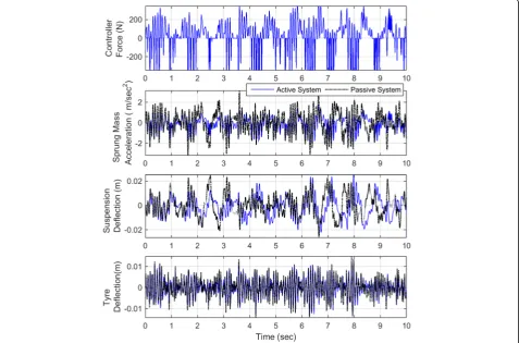
Parameter Fuzzy logic control-GA PID-GA PID classical Passive system
RMS control force (N) 140.9662 445.4385 346.8979 –
VDV (m/s1.75
) 1.1782 1.4410 1.6174 2.1509
Aw (m/s2
) 0.5057 0.6178 0.6890 0.9322
RMS suspension space deflection (m) 0.0085 0.01007 0.008700 0.009311
RMS tyre deflection (m) 0.0042 0.008864 0.007300 0.004473
Max control force (N) 345.6605 1423.1810 1173.24400 –
Max acceleration (m/s2
) 2.31900 1.8615 2.1800 3.16720
Max suspension space deflection (m) 0.02520 0.03426 0.03050 0.02640
Fig. 12PID control results—frequency domain
Fig. 14Fuzzy logic control results—time domain
are simulated further. Refer to Table 7 for the corre-sponding optimized FLC parameters.
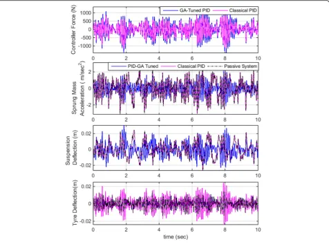
It is observed that RMS acceleration for the GA-optimized FLC is 0.5057 m/s2, which is a little un-comfortable. In the fuzzy logic control system, RMS ac-celeration is reduced by 46% as compared to the passive system (passive suspension system has RMS acceleration 0.9322 m/s2 which is uncomfortable) and by 18% as compared to GA-based PID controller. Also, VDV for GA-based FLC is reduced by 45% as compared to the passive suspension system and by 18% as compared to the GA-based PID controller. Also, the RMS suspension space and RMS tyre deflection are less for FLC as
compared to the GA-based PID controller and passive suspension system. The constraints are not violated in GA optimized FLC. The results of RMS optimal control force, RMS sprung mass acceleration, RMS suspension space, RMS dynamic tyre deflection, and maximum controller force are maximum sprung mass acceleration are tabu-lated in Table 5 (refer to Fig. 14 for the time domain results). Results are also shown in the bar chart (refer to Fig.15).
From simulations and Table 5, it is observed that the GA-tuned FLC controller performs better as compared to the GA-tuned PID controller. In the case of GA-tuned FLC controller, VDV and RMS acceleration is
Fig. 16Fuzzy logic control results—frequency domain
reduced by 18.23% and 18.14% as compared to the GA-tuned PID controller. Also, RMS suspension space deflection and RMS tyre deflection is less for the GA-tuned FLC controller.
Further, the frequency domain analysis is also carried out for the FLC system and passive system. For fre-quency analysis, it is observed that the FLC system expe-riences low amplitudes of vibrations over a broader range of frequencies as compared to the passive suspen-sion system (refer to Fig. 16). The FLC can reduce the amplitude of body accelerations at points 100 and 101 Hz frequencies and also shows better performance over higher amplitude regions > 10 Hz.
Further, to study the controller performance, the non-linear quarter car suspension system is simulated over class C and class D roads with vehicle speed ranging from 20 to 160 kmph. Figure 17 shows performance over class C road type. For class C road, the maximum value of VDV is 1.8385 m/s1.75 and is observed at 160 kmph, for GA-tuned PID controller. Whereas for
the GA-based FLC maximum VDV is 1.7205 m/s1.75. The maximum value of RMS sprung mass acceleration is 0.7910 m/s2 for the GA-tuned PID controller and 0.7065 m/s2for the GA-FLC controller and is observed at 160 kmph. From Fig.17, it is observed that, for FLC controller, up to 130 kmph speed, the RMS sprung mass acceleration is in a slightly uncomfortable region as per ISO2631-1:1997. Whereas for the PID controller, the same level is achieved up to 100 kmph. Above these speed limits, the RMS sprung mass acceleration falls under the fairly uncomfortable region. Other parameters like RMS suspension space and RMS tyre deflection are also represented in Fig.17.
The non-linear quarter car is also simulated over class D road. Figure18shows the performance of the nonlin-ear quarter car with both controllers over class D road. From the figure, it is observed that FLC and PID con-troller shows nearly the same performance for the RMS sprung mass acceleration. The VDV value is maximum at 160 kmph for both controllers. The maximum VDV
for PID controller is 2.1874 m/s1.75and for FLC controller VDV is on the slightly higher side and is 2.6091 m/s1.7. The maximum RMS sprung mass is the acceleration is observed at 160 kmph for both controllers and is 0.9391 m/s2 for the GA-tuned PID controller and 0.9586 m/s2 for GA-FLC controller respectively. From Fig. 18, it is observed that for FLC controller, up to 80 kmph speed, the RMS sprung mass acceleration is in a slightly uncomfortable region whereas for PID controller, the same level is achieved up to 70 kmph as per ISO2631-1:1997. Above these speed limits, RMS sprung
mass acceleration falls under the fairly uncomfortable region.
To check the effect of vibrations on a human body, the suspension system along with the human model is simulated. The nonlinear quarter car along with seat and human model is simulated using PID and FLC system and compared with a passive system. VDV at the head, RMS head acceleration, crest factor, and amplitude ratios are observed.
Crest factor (CF) is defined as the ratio of maximum head acceleration to the RMS head acceleration [26].
C F¼Max ah
! = 1
T
Z T
0
awhð Þt
½ 2
dt
1
2
ð12Þ
The amplitude ratio of head RMS acceleration to seat RMS acceleration (AR_h) is defined as the ratio of the RMS head acceleration to the RMS seat acceleration (Nagarkar et al.2016).
Fig. 18Performance of FLC and PID controller—class D road
Table 6Human model results—FLC, PID, and passive system
Parameter FLC PID Passive system
VDV_h (m/s1.75) 2.8938 2.8787 4.8180
Aw_h (m/s2) 1.1083 1.1082 2.0408
CF 2.6811 3.3829 3.3109
AR_h 0.9684 1.0192 1.2033
AR h¼ 1 T
Z T
0 a
hð Þt
½ 2
dt
1
2
= 1 T
Z T
0 a
sð Þt
½ 2
dt
1
2
ð13Þ
The amplitude ratio of upper torso RMS acceleration to seat RMS acceleration (AR_ut) is defined as the ratio of the RMS upper torso acceleration to the RMS seat ac-celeration (Nagarkar et al.2016).
AR¼ 1 T
Z T
0 a
utð Þt
½ 2
dt
1
2
= 1 T
Z T
0
asð Þt
½ 2
dt
1
2
ð14Þ
It is observed that the RMS head acceleration is duced by 39% in the case of the GA-based FLC and re-duced by 46% in the case of the GA-based PID controller as compared to the passive suspension system, whereas VDV at the head is reduced by 39% and 41% for
Fig. 19Human model results
FLC and PID controller as compared to the passive sys-tem. CF, AR_h, and AR_ut parameters are reduced for FLC as compared to the PID and passive suspension sys-tem. Results are tabulated in Table6 and are presented in the bar chart (refer to Fig.19).
From Table 6 and Fig. 19, it is observed that the GA-tuned FLC has RMS acceleration of head and VDV at head slightly greater (1.9% and 1%
respectively) as compared to the GA-tuned PID con-troller. But, FLC gives better results as compared to the PID controller for CF, AR_h, and, AR_ut (20.75%, 4.98%, and 9.07% less respectively as compared to PID controller).
From frequency domain results, it is observed that the PID controller experiences low amplitude of vibrations at the head as compared to the passive system. FLC also
Fig. 21Head acceleration time domain results—FLC and passive suspension system
experiences low amplitude of vibrations at a broader range of frequencies. FLC and PID controller improves amplitude of vibrations at head around 100Hz regions, which is the most sensitive region related to ears and eyes. Refer Figs.20 and21for time domain results and Fig.22for frequency domain results.
Conclusions
This paper presents mathematical modelling, control, and multi-objective optimization of an active nonlinear quarter car suspension system. A nonlinear 2-DoF non-linear quarter car model having quadratic nonnon-linearities in the tyre and cubic nonlinearity in suspension spring is developed and implemented for control applications.
The PID and FLC strategies are implemented on a nonlinear quarter car system. Controller parameters such as P, I, and D parameters of the PID controller and input-output membership functions’ range and scaling factors of the FLC are then tuned using NSGA-II algo-rithm (Table 7). In optimization problem comfort and health criterion consisting of VDV, RMS acceleration, along with stability criterions consisting of suspension space and tyre deflection are used as objective functions. ISO 2631-1 methodology is adopted and successfully implemented. Numerical simulations show that the GA-based FLC active control system minimizes the frequency-weighted RMS ac-celeration and VDV as compared to the PID and passive suspension system thus improving the ride comfort. Results are also presented in the frequency domain which shows that the active control system experiences less amplitude as compared to the passive one.
Further results are extended on a human model, which shows that the active control system shows minimum RMS head acceleration, VDV at the head, crest factor, and amplitude ratio at the head and amplitude ration at upper torso, thus providing comfort with health criterion.
Abbreviations
Aw:Frequency-weighted RMS head acceleration (m/s2); aw:
Frequency-weighted sprung mass acceleration (m/s2); c: Damping coefficient (Ns/m);
ch: Cervical spine damping (Ns/m); clt: Lumber spine damping (Ns/m);
cut: Thoracic spine damping (Ns/m);f: Control force (N); fobj: Objective
function; k: Stiffness (N/m); ke, kec, ku: Scaling factors for error, change in error, and force respectively; kh: Cervical spine stiffness (N/m); klt: Lumber
spine stiffness (N/m); Kp, Ki, Kd: PID gains—proportional, integral, and derivative respectively; ksnl: Nonlinear spring stiffness (N/m3); kt: Tyre stiffness
(N/m); ktnl: Nonlinear tyre stiffness (N/m2); kut: Thoracic spine stiffness (N/m);
m: Mass (kg); no: Reference spatial frequency = 0.1(cycles/m);
Sq(no): Coefficient of road roughness; v: Velocity (m/s); VDV: Vibration dose
value (m/s1.75); w(t): White noise signal having PSD = 1; x,ẋ,ẍ: Displacement
(m), velocity (m/s), and acceleration (m/s2); x
r: Road profile (m);
Subscripts
c: Seat cushion; f: Frame; h: Head; lt: Lower torso; s: Sprung; t: Thigh and pelvis; us: Unsprung; ut: Upper torso
Acknowledgements
The first author likes to express his deep gratitude towards the management of Ahmednagar Jilha Maratha Vidya Prasarak Smamaj, Ahmednagar, and likes to thank the Principal, SCSMCoE, Ahmednagar, for their encouragement and constant support to carry out this research work. The first author also likes to thank Springer Nature and Springer Nature Waiver team for their generous help and constant support during this work.
Funding
Not applicable.
Availability of data and materials
Not applicable.
Authors’contributions
MPN has been involved in the optimization, simulation, and drafting. YJB, GJV, and RNZ have been involved in the drafting of the manuscript and revising it critically for important intellectual content. All authors read and approved the final manuscript.
Competing interests
The authors declare that they have no competing interests.
Publisher’s Note
Springer Nature remains neutral with regard to jurisdictional claims in published maps and institutional affiliations.
Author details
1
SCSM College of Engineering, Ahmednagar, MS 414005, India.2Research Department of Mechanical Engineering, AVCoE, Sangamner, MS, India.
3
Professor, Mechanical Engineering Department, MIT Academy of Engineering, Alandi, Pune, MS 412105, India.4DVVP CoE, Vilad Ghat,
Ahmednagar, MS 414111, India.
Received: 21 July 2018 Accepted: 25 October 2018
References
Abdelrassoul, R., Ali, Y., & Zaghloul, M. S. (2016). Genetic algorithm-optimized PID controller for better performance of PV system. InProceedings - 2016 world symposium on computer applications and research, WSCAR 2016(pp. 18–22).
https://doi.org/10.1109/WSCAR.2016.14.
Alander, J. T. (1992). On optimal population size of genetic algorithms. In
CompEuro 1992 Proceedings computer systems and software engineering(pp. 65–70).https://doi.org/10.1109/CMPEUR.1992.218485.
Amato, F. J. D., & Viassolo, D. E. (2000). Fuzzy control for active suspensions.
Mechatronics, 10(8), 897–920.https://doi.org/10.1016/S0957-4158(99)00079-3. Baumal, A. E., McPhee, J. J., & Calamai, P. H. (1998). Application of genetic
algorithms to the design optimization of an active vehicle suspension system.Computer Methods in Applied Mechanics and Engineering, 163(1–4), 87–94.https://doi.org/10.1016/S0045-7825(98)00004-8.
Boileau, P., & Rakheja, S. (1998). Whole-body vertical biodynamic response characteristics of the seated body biodynamic response under vertical vibration.Journal of Sound and Vibrations, 215(4), 841–862.https://doi.org/10. 1016/S0169-8141(97)00030-9.
Bouarroudj, N., Boukhetala, D., Djari, A., Rais, Y., & Benlahbib, B. (2017). FLC based Gaussian membership functions tuned by PSO and GA for MPPT of photovoltaic system: a comparative study. In2017 6th international conference on systems and control, ICSC 2017(pp. 317–322).https://doi.org/10. 1109/ICoSC.2017.7958640.
Bovenzi, M. (2005). Health effects of mechanical vibrations.Giornale Italiano di Medicina del Lavoro ed Ergonomia, 27(1), 58–64.
Table 7Controller parameters after optimization
Type Controller parameters
PID Classical: KP = 3055, KI = 0.7; KD = 32,060.
Optimized: KP = 200, KI = 50.9245; KD = 48,176.4
FLC Ke =−0.2806, Kec =−4.0721; Ku = 15.9754,
Celin, P. S., & Rajeswari, K. (2012). GA tuned Type-2 fuzzy logic controller for vehicle suspension system. InProceedings: international conference on computing, electronics and electrical technologies [ICCEET](pp. 383–388). Kumaracoil.https://doi.org/10.1109/ICCEET.2012.6203863.
Chen, H., & Chang, S. (2006). Genetic algorithms based optimization design of a PID controller for an active magnetic bearing.IJCSNS International Journal of Computer Science and Network Security, 6(12), 95–99.
Deb, K., Pratap, A., Agarwal, S., & Meyarivan, T. (2002). A fast and elitist multiobjective genetic algorithm: NSGA-II.IEEE Transactions on Evolutionary Computation, 6(2), 182–197.https://doi.org/10.1109/4235.996017. Fuller, C. R., Elloit, S. J., & Nelson, P. A. (1996).Active control of vibrations. London:
Academic Press.
Gad, S., Metered, H., Bassuiny, A., & Abdel Ghany, A. (2017). Multi-objective genetic algorithm fractional-order PID controller for semi-active magnetorheologically damped seat suspension.Journal of Vibration and Control, 23(8), 1248–1266.https://doi.org/10.1177/1077546315591620. He, L., Qin, G., Zhang, Y., & Chen, L. (2008). Non-stationary random vibration
analysis of vehicle with fractional damping.2008 International Conference on Intelligent Computation Technology and Automation (ICICTA), 2, 150–157.
https://doi.org/10.1109/ICICTA.2008.348.
Hernández-Díaz, A. G., Coello, C. A. C., Pérez, F., Caballero, R., Molina, J., & Santana-Quintero, L. V. (2008). Seeding the initial population of a multi-objective evolutionary algorithm using gradient-based information. In2008 IEEE congress on evolutionary computation, CEC 2008(pp. 1617–1624).https://doi. org/10.1109/CEC.2008.4631008.
Holland, J. H. (1975).Adaptation in natural and artificial systems. Michigan: MIT Press.
Holland, J. H. (1992). Genetic algorithms.Scientific American, 267(1), 66–72.https:// doi.org/10.1038/scientificamerican0792-66.
Huang, S. J., & Chao, C. H. (2000). Fuzzy logic controller for a vehicle active suspension system.Proceedings of the Institution of Mechanical Engineers, Part D: Journal of Automobile Engineering, 214(1), 1–12.https://doi.org/10.1243/ 0954407001527178.
ISO 2631-1 (1997) Mechanical vibration and shock - Evaluation of human exposure to whole-body vibration.
ISO 8608. (1995).Mechanical vibration–Road surface profile–Reporting of measured data(1st ed.).
Kalaivani, R., Lakshmi, P., & Sudhagar, K. (2014). Hybrid (DEBBO) fuzzy logic controller for quarter car model. InProceedings - UKACC international conference on control(pp. 301–306). Loughborough.
Kesarkar, A. A., & Selvaganesan, N. (2015). Tuning of optimal fractional-order PID controller using an artificial bee colony algorithm.Systems Science and Control Engineering, 3(1), 99-105.https://doi.org/10.1080/21642583.2014. 987480.
Li, P., & Du, X. (2006). A GA optimization for FLC with its rule base and scaling factors adjustment. InProceedings: International Conference on Intelligent Computing-Part II(pp. 1–10). Kunming.https://doi.org/10.1007/11816171_1. Liu, Y.-H., Wang, S.-C., & Peng, B.-R. (2016). Determining optimal membership
functions of a FLC-based MPPT algorithm using the particle swarm optimization method. InProceedings - 2016 5th IIAI international congress on advanced applied informatics, IIAI-AAI 2016.https://doi.org/10.1109/IIAI-AAI. 2016.123.
Lixia, J., & Wanxiang, L. (2008). Chaotic vibration of a nonlinear quarter -vehicle model. InProceedings - IEEE vehicle power and propulsion conference(pp. 1–4). Harbin.
McGee, C., Haroon, M., Adams, D., & Luk, Y. (2005). A frequency domain technique for characterizing nonlinearities in a tire-vehicle suspension system.Journal of Vibration and Acoustics, 127(1), 61–76.https://doi.org/10. 1115/1.1855931.
Metered, H., Elsawaf, A., Vampola, T., & Sika, Z. (2015). Vibration control of MR-damped vehicle suspension system using PID controller tuned by particle swarm optimization.SAE International Journal of Passenger Cars - Mechanical Systems, 8(2), 01–0622.https://doi.org/10.4271/2015-01-0622.
Nagarkar, M. P., Vikhe Patil, G. J., & Zaware Patil, R. N. (2016). Optimization of nonlinear quarter car suspension–seat–driver model.Journal of Advanced Research, 7(6), 991–1007.https://doi.org/10.1016/j.jare.2016.04.003. Niu, X. (2014). The optimization for PID controller parameters based on genetic
algorithm.Applied Mechanics and Materials, 513-517, 4102–4105.https://doi. org/10.4028/www.scientific.net/AMM.513-517.4102.
Rajendiran, S., & Lakshmi, P. (2016). Simulation of PID and fuzzy logic controller for integrated seat suspension of a quarter car with driver model for
different road profiles.Journal of Mechanical Science and Technology, 30(10), 4565–4570.https://doi.org/10.1007/s12206-016-0927-6.
Rosenthal, S., & Borschbach, M. (2014). Impact of population size and selection within a customized NSGA-II for biochemical optimization assessed on the basis of the average cuboid volume indicator. InProceedings - Sixth International conference on bioinformatics, biocomputational systems and biotechnologies(pp. 1–7). Chamonix: BIOTECHNO.
Salem, M. M. M., & Aly, A. A. (2009). Fuzzy control of a quarter-car suspension system.World Academy of Science, Engineering and Technology, 53, 258–263. Song, L. (2011).NGPM-A NSGA-II Program in Matlab - User Manual. Version 4.1(pp.
1–20).
Song, L. (2015). NGPM-A NSGA-II Program in Matlab v14. Matlab Code.http://in. mathworks.com/matlabcentral/fileexchange/31166-ngpm-a-nsga-ii-program-in-matlab-v1-4. Accessed on 15 Mar 2015.
Talib, M. H. A., & Darus, I. Z. M. (2014). Development of fuzzy logic controller by particle swarm optimization algorithm for semi-active suspension system using magneto-rheological damper.WSEAS Transactions on Systems and Control, 9, 77–85.
Tammam, M. A., Magdy, A. S., Aboelela, M. A., Moustafa, & Seif, A. E. A. (2013). A multi-objective genetic algorithm based PID controller for load frequency control of power systems.International Journal of Emerging Technology and Advanced Engineering, 3(12), 463–467.
Taskin, Y., Hacioglu, Y., & Yagiz, N. (2007). The use of fuzzy-logic control to improve the ride comfort of vehicles.Strojniski Vestnik/Journal of Mechanical Engineering, 53(4), 233–240.
Taskin, Y., Hacioglu, Y., & Yagiz, N. (2017). Experimental evaluation of a fuzzy logic controller on a quarter car test rig.Journal of Brazilian Society of Mechanical Science and Engineering, 39(7), 2433–2445. https://doi.org/10.1007/s40430-016-0637-0.
Van Niekerk, J. L., Pielemeier, W. J., & Greenberg, J. A. (2003). The use of SEAT effective amplitude transmissibility (SEAT) values to predict dynamic seat comfort.Journal of Sound and Vibration, 260(5), 867–888.https://doi.org/10. 1016/S0022-460X(02)00934-3.
Wong, J. Y. (2001).Theory of ground vehicles. NY: Wiley.
Zhang, Y., Chen, W., Chen, L., & Shangguan, W. (2007). Non-stationary random vibration analysis of vehicle with fractional damping. InProceedings - 13th national conference on mechanisms and machines (NaCoMM07)(pp. 171–178). Bangalore.
Zhu, Q., & Ishitobi, M. (2006). Chaotic vibration of a nonlinear full-vehicle model.