This is a repository copy of
3D Electromagnetic Diffusion Models for Reverberant
Environments
.
White Rose Research Online URL for this paper:
http://eprints.whiterose.ac.uk/120554/
Version: Accepted Version
Proceedings Paper:
Flintoft, I. D. orcid.org/0000-0003-3153-8447 and Dawson, J. F.
orcid.org/0000-0003-4537-9977 (2017) 3D Electromagnetic Diffusion Models for
Reverberant Environments. In: 2017 International Conference on Electromagnetics in
Advanced Applications (ICEAA). 2017 International Conference on Electromagnetics in
Advanced Applications (ICEAA), 11-15 Sep 2017 , Verona , pp. 511-514.
https://doi.org/10.1109/ICEAA.2017.8065293
[email protected] https://eprints.whiterose.ac.uk/ Reuse
["licenses_typename_other" not defined]
Takedown
If you consider content in White Rose Research Online to be in breach of UK law, please notify us by
________________________________________________________________________________________
1Department of Electronic Engineering, University of York, Heslington, York, UK, YO10 5DD. e-mail: [email protected], tel.: +44 1904 322391; [email protected], tel: +44 1904 322356.
3D Electromagnetic Diffusion Models for Reverberant
Environments
I. D. Flintoft
1J. F. Dawson
1Abstract Diffusion equation based modeling has been
proposed for mapping the reverberant component of the electromagnetic field in enclosures at high frequencies. Preliminary evaluation of the electromagnetic diffusion model using a dimensional reduction approach showed promising results compared to measurements. Here we develop a full three-dimensional diffusion model of the experimental canonical test cases considered in the preliminary evaluation and obtain finite element method solutions. The results are compared to those of the two-dimensional models. We find that the two- and three-dimensional models are generally in excellent agreement for the pseudo two-dimensional test-cases considered. Some deviations between the two- and three-dimensional models are observed due to the fact the point source must be effectively represented by a line source in the reduced model. The three-dimensional model is still highly efficient compared to other applicable techniques, offering the prospect of a radical reduction in the resources required for simulating reverberant fields in electrically large structures.
1 INTRODUCTION
Full-wave electromagnetic (EM) simulations which solve Maxwell’s equation directly can become extremely costly in terms of computational resources when applied to electrically large enclosed spaces. Even when such resource is available the boundary conditions in real complex systems are rarely know with sufficient accuracy for a single deterministic simulation of the structure to provide the desired engineering results; multiple simulations are therefore often required, maybe as part of a Monte Carlo Method approach, in order to provide estimates of the statistical distribution of the observables of interest. More efficient asymptotic energy methods have therefore been developed with a range of underlying assumptions and levels of approximation.
The power balance (PWB) method of Hill et al assumes the energy density in an enclosure is uniform and makes strong assumptions about the statistics of the diffuse field [1]. The PWB model provides very fast results, but it cannot account for the inhomogeneity in the diffuse field arising from any loss in the cavity. Examples of where this limitation is potentially significant include reverberation chamber (RC) measurements made with significant loading to replicate multipath environments for antenna measurements and estimating the exposure of people to diffuse fields in enclosed spaces [2],[3].
Therefore in [4], we evaluated a statistical energy method of intermediate sophistication, based on the diffusion equation, which we have called the electromagnetic diffusion model (EDM). This
approach is based on that developed by the acoustics community and it can account for the variation of the diffuse energy density in enclosed spaces due to the presence and distribution of losses on the walls and contents of the enclosure. Recent reviews of the acoustic diffusion model (ADM) are given in [5], [6]. The diffusion method can be rigorously derived from a more advanced radiative transport theory of rays in the enclosure and can be seen as a natural generalization of the PWB method in both the time and frequency domains. The computational burden of the EDM, while significantly higher than that of PWB, is still substantial lower than that of ray tracing or full-wave simulation.
For the initial evaluation, we made use of a dimensional reduction technique to construct two-dimensional (2-D) models for some canonical test cases consisting of single and dual cavities loaded with radio absorbing material (RAM). The results compared reasonably well with experimental data. In this paper we present the first simulations of the full 3-D EDM applied to the same set of canonical test cases and compare the results to the 2-D simulations.
2 THE DIFFUSION MODEL
The assumptions underlying the electromagnetic diffusion model and its derivation are detailed in [4]; here we briefly summarize the main features. The model assumes the existence of a diffuse EM field with average energy density ( , ) = ( , )| , where ( , )is the electric field. Here denotes an average over a statistical ensemble of systems, for example, mode tuning configurations in an RC or variations in the boundary conditions due to the contents inside an enclosure. The diffuse field can be considered to be constituted of a collection of rays. The scalar power density, ( , ), of the classic Hill et al plane-wave analysis of an ideal diffuse field [7] is related to the average energy density, ( , ),by
( , ) = c ( , ) . (1)
The diffuse electromagnetic energy density within the volume of an enclosed space, V, is assumed to satisfy a diffusion equation
( ) + ( , )
= ( ) ( )( ) (2)
where ( ) is the (potentially inhomogeneous)
© 2017 IEEE. Personal use of this material is permitted. Permission from IEEE must be obtained for all other uses, in any current or future media, including reprinting/republishing this material for advertising or promotional purposes, creating new collective works, for resale or redistribution to servers or lists, or reuse of any copyrighted component of this work in other works.
diffusivity, is a volumetric energy loss rate due to absorption by the cavity contents and we have assumed there is a single time-dependent isotropic point source of total radiated power (TRP) ( ) located at . The diffusivity is related to the overall mean-free-path (MFP), , between scatterings of the rays from the walls and contents of the cavity by
= c 3 . (3)
For a simply connected convex cavity the diffusivity due to the walls is well described by taking the MFP to be given by the value determined from the classic room acoustics estimate of the reverberation time [5]
= 4 . (4)
The overall MFP is the harmonic mean of the MFP of the walls and contents. For sparsely populated enclosures the MFP of the walls dominates and we can assume . Details on accounting for the contents in the determination of the diffusivity can be found in [4].
On the boundary surface of the volume, denoted by , the energy density is assumed to satisfy a Robin flux type boundary condition (BC)
( ) + c ( ) ( , ) = 0 (5)
where c is the speed of light, is an outward unit normal vector and ( )is an absorption factor related to the dissipation of energy in the walls. Due to the geometric optics propagation assumption the electromagnetic wavelength only enters the model via the frequency dependence of the absorption processes within the cavity described by and ( ). The absorption in the contents described by can also be accounted for by including the surfaces of the contents explicitly in the model and applying an appropriate loss factor on those surfaces. This is the approach taken in this paper, so we will focus on the loss factor
( ).
Consideration of the full electromagnetic solution of the cavity shows the loss factor for a diffuse field at a surface is given by
( ) ( ) 4 (6)
where ( ) is the average power absorption efficiency of the surface. This can be determined from the reflection coefficient of the surface by averaging the flux of the normal component of the Poynting vector over the arrival angles and polarizations of the rays [8]. This relation is analogous to Sabine’s formula in acoustics [9] and its derivation assumes the diffused rays arrive at random angles but undergo specular reflections from the walls. A radiative transport derivation of the diffusion model leads to the more general expression
( ) = ( )
( ) (7)
for the absorption factor [5]. This model assumes the reflection process at the surface is itself diffusive, i.e. the power reflectance is independent of the angle of incidence. For low absorption (7) predicts a loss factor that is close to that of the Sabine formula above; however, for high absorption the loss factor approaches twice that of Sabine’s formula.
An isotropic diffuse point source is included in (2). The time independent Green’s function for this diffusion equation in an unbounded space is given by [10]
( | ) =
| |exp | | .(8)
This includes a spurious “direct” term
; ( ) = 4 | (9)
close to the source which Visentin et al argue should be subtracted from the solution to give the true reverberant energy density
( ) = ( )
| |. (10)
The physically correct direct energy from the source is determined using
( ) =
| | . (11)
In contrast to the result reported in [4], in this paper we shall consider the effects of the direct term and present results for the reverberant energy density, ( ), and the associated scalar power density, ( ) = c ( ).
Two cavities coupled through an electrically large aperture can be treated as a single computational domain in the EDM, with no special treatment of the aperture. This method assumes that the field in the aperture is well diffused, which is only a good approximation for apertures well above their resonant frequency. Providing the coupling area is not too large each cavity’s diffusivity and loss rate will be approximately determined by its own respective geometry and absorption characteristics and unaffected by the coupling. In order to accurately model apertures that are either electrically small or in the resonant regime coupled energy exchange BCs can be used as described in [4].
3 CANONICAL TEST CASE
In this section, we briefly recall the geometry of the canonical test cases defined in [4]. They are based on a physical cuboid cavity defined as occupying the
volume , and as
Table 1. The cavity is excited by an isotropic source of total radiated power = 1 W at the position ( . An absorbing cylinder having a radius and a height is positioned in the cavity, with its axis in thez-direction, centered at( .The cavity is partitioned into two sub-cavities using a metal plate which leaves a slot of width over the full height of
the cavity located in the region ,
[image:4.595.84.279.237.342.2]of the shared wall. The walls and cylinder have homogeneous absorption efficiencies of and respectively. The values are determined from measurements of the cavity and cylinder [4].
Figure 1: Cross-section of the cuboid cavity used for the canonical examples and validation measurements here and in [4].
Parameter Value Parameter Value
0.45 m 0.01 m
0.45 m 0.225 m
d 0.04 m 0.225 m
0.05 m 1 W
0.0027 (dual) 0.675 m
Table 1: Parameter values for the canonical examples. Note that the position of the cylinder is slightly different in the single and dual cavity examples.
4 FINITE ELEMENT SOLUTION
The finite element method (FEM) was used to solve the 2-D EDM for the canonical test cases in [4] and the 3-D test case presented here. We used the FreeFEM++ package to implement the FEM solutions, with a Lagrangian polynomial finite element basis [11]. In this paper the coupled cavities were simulated using a single domain with homogeneous diffusivity and the contents were modeled by including their surfaces in the mesh and applying a Robin BC with the appropriate loss factor determine using the Sabine formula (6). 3-D meshes were generated using the parametric CAD package Gmsh [12].
Figure 2 shows a section through the mesh for the cavity loaded with a RAM cylinder. The 1 W point source (not shown in Figure 2) is located at the opposite end of the cavity to the cylinder. The 3-D
[image:4.595.317.517.307.433.2]FEM solution took a few seconds on a desktop computer.
[image:4.595.101.262.401.469.2]Figure 2: Tetrahedral mesh of the coupled cavities test-case containing the lossy cylinder.
Figure 3: Isosurfaces (in dB W∙m-2
) of the reverberant scalar power density in the coupled cavities loaded with the lossy cylinder ( = 0.95).
5 RESULTS
We present some preliminary results for the dual cavity example loaded with a cylinder with = 0.95, corresponding to the physical cylinder in [4]. As this simulation was made using a single computational domain with the diffusivity in each sub-cavity determined from (3) and (4) using the surface area and volume of the whole as a single cavity; it therefore does not account for the effect of the cylinder on the diffusivity in the coupled cavity.
supra-resonant must be borne in mind.
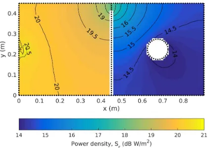
[image:5.595.77.288.301.450.2]The power density at the half-height of the cavity is shown in Figure 4. The variation in the source cavity is about 2.5 dB while that in the coupled cavity is about 4 dB. In the coupled cavity the deepest “shadow” is cast behind the cylinder in the direction away from the aperture. Compared to the 2-D solution in [4], Fig. 14 the qualitative behavior is similar, but the levels are a little different. The ratios of the volume average power densities, , in the source and coupled cavities to their respective PWB predictions are -54 % and +29 %. This is presumably because the current 3-D model does not account for the inhomogeneous diffusivity caused by the introduction of the cylinder. The 2-D model properly accounted for this using a domain decomposition technique; further work is continuing to apply the same approach in the 3-D EDM.
Figure 4: Diffuse power density, r
( )
, in the plane at the half-height of the dual cavities loaded with the absorbing cylinder (with ca = 0.95). Compare to the2-D simulation results in [4], Fig. 14.
6 CONCLUSIONS
3-D EDM models have been implemented using the FEM and applied to canonical examples of a cavity loaded with absorber. Preliminary results suggest that the 2-D EDM, using a Kantorovich dimensional reduction approach, generally gives reasonably accurate results compared to the full 3-D solution when approximate 2-D symmetry exist, however discrepancies begin to increase with loading. The implementation of the 3-D EDM opens the way for investigations of more complex applications such as high frequency enclosure shielding.
References
[1] D. A. Hill, M. T. Ma, A. R. Ondrejka, B. F. Riddle, M. L. Crawford and R. T. Johnk, “Aperture excitation of electrically large, lossy cavities”, IEEE Trans. Electromagn. Compat., vol. 36, no. 3, pp. 169-178, Aug. 1994.
[2] K. A. Remley, J. Dortmans, C. Weldon, R. D. Horansky, T. B. Meurs, C.-M. Wang, D. F. Williams, C. L. Holloway P. F. Wilson, “Configuring and verifying reverberation chambers for testing cellular wireless devices”, IEEE Trans. Electromagn. Compat., vol. 58, no. 3, pp. 661-672, Jun. 2016.
[3] I. D. Flintoft, G. C. R. Melia, M. P. Robinson, J. F. Dawson and A. C. Marvin, “Rapid and accurate broadband absorption cross-section measurement of human bodies in a reverberation chamber”, IOP Meas. Sci. Techn., vol. 26, no. 6, art. No. 065701, pp. 1-9, Jun. 2015.
[4] I. D. Flintoft, A. C. Marvin, F. I. Funn, L. Dawson, X. Zhang, M. P. Robinson and J. F. Dawson, “Evaluation of the diffusion equation for modelling reverberant electromagnetic fields”,IEEE Trans. Electromagn. Compat., vol. 59, no. 3, pp. 760–769, Jun. 2017.
[5] J. M. Navarro and J. Escolano, “Simulation of building indoor acoustics using an acoustic diffusion equation model”, Journal of Building Performance Simulation, vol. 8, no. 1, pp. 3-14, 2015.
[6] L. Savioja and U. Peter Svensson, “Overview of geometrical room acoustic modeling techniques”, J. Acoust. Soc. Am., vol. 138, no .2, pp. 708– 730, 2015.
[7] D. A. Hill, “Plane wave integral representation for fields in reverberation chambers”, IEEE Trans. Electromagn. Compat., vol. 40, no. 3, pp. 209-217, Aug. 1998.
[8] Hill, D. A. , "A Reflection Coefficient Derivation for the Q of a Reverberation Chamber" , IEEE Transactions on Electromagnetic Compatibility,
vol. 38, no. 4, 169-178 , Nov, 1996
[9] W. C. Sabine, Collected Papers on Acoustics, Harvard University Press, 1922.
[10] C. Visentin, N. Prodi and V. Valeau, “A numerical investigation of the Fick’s law of diffusion in room acoustics”, J. Acoust. Soc. Am., vol. 132, no. 5, pp. 3180–3189, 2012. [11] F. Hecht, “New development in FreeFEM++”,
Journal of Numerical Mathematics, vol. 20, no. 3-4, pp. 251–265, 2012.
![Figure 1: Cross-section of the cuboid cavity used forthe canonical examples and validation measurementshere and in [4].](https://thumb-us.123doks.com/thumbv2/123dok_us/7748580.166877/4.595.84.279.237.342/figure-cross-section-cuboid-canonical-examples-validation-measurementshere.webp)