UNIVERSITI TEKNIKAL MALAYSIA MELAKA
CONTROL OF FIVE DC MOTOR FOR APPLICATION IN ROBOT
MANIPULATOR
This report submitted in accordance with requirement of the Universiti Teknikal Malaysia Melaka (UTeM) for the Bachelor Degree of Manufacturing Engineering
(Robotic and Automation) with Honours.
By
SONG CHIEN SHYEN
DECLARATION
I hereby, declared this report entitled “Control of Five DC Motor For Application In Robot Manipulator” is the results of my own research except as cited in references.
Signature : ...
Author’s Name :Song Chien Shyen
APPROVAL
This report is submitted to the Faculty of Manufacturing Engineering of UTeM as a partial fulfilment of the requirements for the degree of Bachelor of Manufacturing Engineering (Robotics and Automation) with Honours. The member of supervisory committee is as follow:
(Signature of Supervisor)
...
i
ABSTRACT
ii
ABSTRAK
iii
DEDICATION
iv
ACKNOWLEDGEMENT
I would like to thank firstly Encik Muhamad Arfauz Bin A.Rahman for willingly take me as my Final Year Project’s Principal Supervisor for the first semester of academic session 2008/09, and Puan Syamimi Binti Shamsuddin also whom willingly take as my Final Year Project’s Principal Supervisor for the second semester of academic session 2008/09. Without your constant guidance, this project will never be a success. Then I would like to extend my humble gratitude to Encik Hisham bin Nordin, without your advice I would not have completed my controller.
To my panels who took their precious time for themselves off to read about my project, Pn Silah Hayati Binti Kamsani and Dr Zamberi B. Jamaludin, I would like to thank you with all my heart.
To my family and beloved ones, who constantly gives me support morally and financially, thank you so much. Without support from you all, nothing will materialize.
To my friends, especially Parameswara, Tham, Aaron, Denis Chua, Anbalagan, and whomever who have helped me, without your constant pushing and help in ways of your expertise, my project will not be as what it is today.
Thank you…!
v
TABLE OF CONTENT
Abstract i
Abstrak ii
Dedication iii
Acknowledgment iv
Table of Content v
List of Tables ix
List of Figures x
List Abbreviations xiv
1. INTRODUCTION 1
1.1 Objective 2
1.2 Scope 2
1.3 Benefit of this Project 3
2. LITERATURE REVIEW 4
2.1 DC Motor 4
2.1.1 Lorentz Force 6
2.1.2 Kirchoff’s Voltage Law 8
2.1.3 Magnetomotive Force (mmf) 8
2.1.4 Induced Voltage 8
2.1.5 Neutral zones 9
2.1.6 Generation of DC Voltage 10
2.1.7 Improvement of DC output Waveform 11
2.1.8 Counter-electromotive force (cemf) 13
2.1.9 Armature Reaction 14
vi
2.2 Mechanical Properties of DC Motor 15
2.2.1 Acceleration of the DC Motor 16
2.2.2 Power and Torque 17
2.3 Types of DC Motor 18
2.3.1 Shunt Dc Motors 19
2.3.2 Series DC Motor 21
2.3.3 Compound DC Motor 22
2.3.4 Advantages and Disadvantages 23
2.3.4.1 Between three types of DC motor 23
2.3.4.2 Between Alternating Current (AC) and DC 26
2.4 Control of DC Motor 29
2.5 Robotic Arm 30
2.6 Control of DC motor in Robotic Arm 35
2.6.1 Relay 36
2.7 Materials 38
2.7.1 What is Stainless Steel? 38
2.7.2 Role of Alloying Elements in Stainless Steel 40
2.7.2.1 Carbon 40
2.7.2.2 Chromium (Cr) 40
2.7.2.3 Nickel (Ni) 41
2.7.2.4 Molybdenum 41
2.7.2.5 Manganese 41
2.7.2.6 Silicon and Copper 41
2.7.2.7 Nitrogen 42
2.7.2.8 Niobium 42
2.7.2.9 Titanium 42
2.7.2.10 Sulphur 43
2.7.3 More about stainless steel 44
2.7.3.1 Martensitic Stainless Steel 44
2.7.3.2 Ferritic Stainless Steel 45
vii
2.7.3.4 Duplex Stainless Steel 46
2.7.4 Nonferrous Alloy Steels 47
2.7.4.1 Aluminum and Aluminum Alloys 47
3. METHODOLOGY 52
3.1 Research 52
3.1.1 Determination of objectives and scopes for first stage of project 54
3.1.2 Research on DC motor 54
3.1.3 Research on control of DC motor, robot arm and controlling DC motor 54 on robot arm
3.1.4 Conceptual Design 55
3.1.5 Determination of Design to Use 56
3.1.6 Technical Drawing of the Design 57
3.1.7 Material Selection 57
3.1.8 Motor Selection 58
3.2 Project tools and equipments 59
4. DESIGN AND DEVELOPMENT 60
4.1 Design Process 60
4.1.1 Design Determination 67
4.2 Material Selection 68
4.3 Motor Selection 72
4.3.1 Motor Type 73
4.3.2 Operating Voltage and Current 74
4.3.3 Power rating and speed 74
4.3.4 Torque 76
4.4 Development of Robot Arm 77
4.4.1 Base Shaft 78
4.4.2 First Joint Shaft 80
4.4.3 Second Joint Shaft 81
viii
4.4.5 Connector 84
4.4.6 Robot Arm Links 85
4.5 Controller Selection 86
4.5.1 Operation of Standard Controller 87
4.5.2 Development of Controller 89
4.6 Test Design 94
5. RESULT 96
6. DISCUSSION 99
6.1 Work on Project 99
6.2 Second Stage of Project 101
6.3 Result Discussion 102
6.3.1 Robot Arm 103
6.3.2 Controller 105
6.3.3 Testing 105
6.4 Suggestion 107
7. CONCLUSION 108
REFERENCES 109
APPENDICES
A Gantt Chart
B Technical Drawings for Robot Arm
ix
LIST OF TABLES
2.1 Advantages and Disadvantages between Shunt, Series and Compound 26 DC Motor
2.2 Advantages and Disadvantages between AC and DC motor 27 2.3 Typical Robot Application Areas (Rudiger Dillmann, 1990) 31 2.4 Summary of role of elements used in stainless steel 43 2.5 Summary of element content in martensitic stainless steel 44 2.6 Summary of element content in ferritic stainless steel 45 2.7 Summary of element content in austenitic stainless steel 46 2.8 Summary of element content in duplex stainless steel 47 2.9 Typical mechanical properties of various aluminum alloys 50
(Adapted from ASM Handbook Volume 2)
3.1 Properties of DC Motor SPG50-60K 58
3.2 Allow Moment Maximum Wrest Power, Output Power and Weight of 58 DC Motor SPG50-60K
3.3 Reduction Ratio for Shunt DC Motor Used in this Project 58
4.1 Components used for symbols in the Light Dimmer circuit 93
4.2 Bill of material for this project 96
5.1 Criterion on the categories to rate the DC motors for this project 96
x
LIST OF FIGURES
2.1 Figure above shows the similarities of DC generator and DC Motor. 5 (Left) Elementary DC generator construction (Jones and Flynn)(Right) Basic construction of a DC Motor (Siemens Energy and Automation)
2.2 Right Hand Rule applied to determine the direction of force (Siemens 6 Energy and Automation, 2000)
2.3 Maximum force when conductor is perpendicular to the magnetic field 7 2.4 Magnetic field due to magnet and current carrying conductor 7 2.5 Neutral zones located in a DC machine (Wildi, 2000) 10 2.6 Induced voltage obtained from the turning coil of the DC generator 10 2.7 Induced voltage produced for one cycle of DC generator rotation 11 2.8 Schematic diagram of a DC generator having 4 coils in 4 segments and 11
4 commutator bars (Theodore Wildi, 2000)
2.9 A more uniform induced voltage produced than in Figure 2.6(Theodore 12 Wildi, 2000)
2.10 Counter-electromotive force (cemf) in a DC motor (Theodore Wildi, 2000) 13 2.11 Magnetic field produced by the current flowing in the armature conductors 14
(Theodore Wildi, 2000)
2.12 Commutating poles produced an mmf of the commutator that opposes the 15 mmf of the armature (Theodore Wildi, 2000)
2.13 Shunt DC Motor (Shaw) 19
2.14 Torque-speed and torque-current characteristic of a shunt motor (Wildi, 20 2000)
xi
2.18 Typical speed versus torque characteristics of various DC motors (Wildi, 24 2000)
2.19 Graph of efficiency vs speed curves at full load among Brush DC motor, 28 Brushless DC motor and AC motor (Edward C.Lee)
2.20 Open-loop of the control of DC motor 29
2.21 (a) Symbol of a rotary joint. (b) Symbol of a prismatic joint 32 2.22 (a) Rhino-robot with link and joint labeling. (b) Frame assignment of 33
Rhino-robot
2.23 (a) Comau-robot with link and joint labeling. (b) Frame assignment for 34 Comau-Robot
2.24 The workspace for Rhino-robot and Comau-robot drawn by using Autocad 34 2007
2.25 Control of DC motor in Robotic Arm 35
2.26 Flow of signal from the teach pendant to determine the direction of 36 rotation of the DC motor
3.1 Flow chart for the first stage of project 53
3.2 Flow chart for the development of the conceptual robot design (Groover, 55 2008)
3.3 (Left) Slider board of the slider. (Right) Length and width of the slider 57 Board
4.1 (Top left) M-420iA from Fanuc Robotics, (Top right) Comau-Robot, 61 (Below) Rhino-Robot
4.2 Design of Conceptual Design 1 and Frame Assignment 62 4.3 (a) Workspace for Conceptual Design 1 from Top View, (b) Workspace 63
For Conceptual Design 1 from Side View
4.4 Design of Conceptual Design 2 and Frame Assignment 64 4.5 (a) Workspace for Conceptual Design 2 from Top View, (b) Workspace 65
For Conceptual Design 2 from Side View
xii
4.7 (a) Workspace for Conceptual Design 3 from Top View, (b) Workspace 67 For Conceptual Design 3 from Side View
4.8 CAD Drawing and parts labeling of conceptual design 3 67
4.9 Measurement of hollow square aluminum bar 68
4.10 Stress distribution to the robot arm base 70
4.11 Static equilibrium acting on W1 and W2 71
4.12 The approximate length of robot arm when stretched 74 4.13 The structure and labeling of this project’s robot arm 77
4.14 Robot arm fabricated with respect to design 78
4.15 Design of Base Shaft 78
4.16 Fabrication process for Base Shaft 79
4.17 Base Shaft on Base 79
4.18 Design of First Joint Shaft 80
4.19 Fabrication process for First Joint Shaft 80
4.20 First Joint Shaft 81
4.21 Design of Second Joint Shaft 81
4.22 Fabrication process of Second Link Shaft 82
4.23 Second Joint Shaft 82
4.24 Design of Base 83
4.25 Process for the cutting of stainless steel using Laser Cutting Machine 83
4.26 Base as Fabricated 84
4.27 (From left) 2 point connector, 3 point connector 84 4.28 Connection between hollow square using 2 point connector 85
4.29 Design of links for the robot arm 85
4.30 Schematic circuit for the standard controller using Automation Studio 87 4.31 Flow of the current to actuate the DC1 in clockwise motion 88 4.32 Flow of the current to actuate the DC1 in anti-clockwise motion 88
4.33 Testing on the strip board using multimeter 89
4.34 Soldering Set 90
xiii
4.37 Circuit for relay using ISIS Professional 92
4.38 Circuit for relay trigger circuit 92
4.39 Schematic circuit for the Light Dimmer 93
4.40 The circuit of the Light Dimmer 94
4.41 Path of test for the first joint for the robot arm 94 4.42 Test design for movement of Second and Third Joint of the robot arm 95
5.1 Sequence of results taking for this project 97
6.1 The work done on the first stage of the project 100
6.2 Slider to have robot arm to mount on 101
6.3 The process work flow for stage two of project 102 6.4 A 10mm x 10mm aluminum hollow steel used to widen the gap between 104
links
6.5 Waviness of the stainless steel plate due to sudden cooling after welding 104 6.6 Testing using multimeter for bypass on strip board between columns 105
xiv
LIST OF ABBREVIATIONS
AC Alternate Current
Al - Aluminum
C - Carbon
DC - Direct Current
CAD - Computer Aided Drawing cemf - Counter electromotive force
kg - Kilogram
KVL - Kirchoff’s Voltage Law
Mm - milimeter
mmf - Magneto-Motive force
N - North
NC - Normally Closed
NO - Normally Open76
pu - per unit
rad - radians
r/min (rpm) - Revolutions per minute
S - South
UTeM - Universiti Teknikal Malaysia Melaka
V - Voltage
1
CHAPTER 1
INTRODUCTION
2 1.1 Project Aim and Objective
The aim of this project is to control 5 DC motor to be acting as the robot actuating agent. The aim is achieved through these objectives.
(a) To study on the advantages and the functionality of DC Motor and hence its capability as the actuator of robot manipulator
(b) To design and develop a five degree of freedom robot manipulator using DC motor as the actuators.
(c) To design and develop a suitable controller for controlling five DC motor
1.2 Scope
In order to achieve the objectives of this research project, the following are the scope of this research project.
(a) Study on the ability of Cytron DC motor, model 60K and SPG-50-180K, to be applied as the rotational actuator for the robot manipulators.
(b) Study on producing a flexible, reliable and functional relay triggered controller for the robot to determine the direction of rotation for the DC motors.
3 1.3 Benefit of this Project
Upon completing of this project, few benefits can be obtained as follows:
(a) 5 degree of freedom robot structure to be mounted onto the slider to create an extra axis to move around
(b) More insight of the capability and flexibility of the DC motor to be used in the high technology industry.
4
CHAPTER 2
LITERATURE REVIEW
This chapter describes the research that has been done on DC motor. The research includes the theory behind DC Motor, DC motor’s properties, types of DC motor and the control of DC motor in robotic arm. Besides that, the theory of robot is also discussed. Then the types of materials, basis on controllers and electronics used to be used to create a functioning robot arm are discussed.
2.1 DC Motor
5
Figure 2.1: Figure above shows the similarities of DC generator and DC Motor. (Left) Elementary DC generator construction (Jones and Flynn) (Right) Basic construction of a DC Motor (Siemens Energy and Automation)
In DC motor and generator, when the armature or coil rotates, the voltage E is induced in each conductor depending on the density of flux when it cuts. The higher the density of flux, the more induced voltage it will be produced. When induced voltage is passed through the conductors in the armature, rotation of the armature will happen. The reason for this is because of several ideologies such as Faraday’s law and Lorentz force. Faraday’s law states that:-
When a time-varying magnetic field passes through a conducting loop or coil, a voltage is induced in the coil. Conversely, when a time-varying voltage is applied to the terminals of the coil, a time-varying magnetic field is generated (Hi-Dong Chai, 1998).
This means when a time varying voltage is applied onto the armature of the DC motor, a time-varying magnetic field is generated. When a current carrying conductor is moved in a magnetic field, a force is produced in a direction perpendicular to the current and magnetic field directions (G. Alciatore, Michael B. Histand, 2007) and can be related to the Lorentz’s force law.
[image:22.612.144.542.88.226.2]6
2.1.1 Lorentz Force
Michael states Lorentz’s force law as follows:-
F = I x B ………….(2.1) Where:
F is the force vector (per unit length of conductor) I is the current vector
B is the magnetic field vector
This formula applies for one conductor carrying current. If single conductor is replaced by a large number of conductors, the force per unit length is increased by the number of turns in the coil which results in the amount of current induced to be increased.
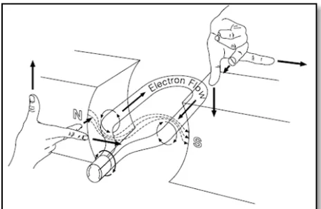
The force direction acting on the armature of the motor can be determined by using the Right Hand Rule. The same rule applies to the DC generator. The Right Hand Rule can be described using Figure 2.2.
Figure 2.2: Right Hand Rule applied to determine the direction of force (Siemens Energy and Automation, 2000)
Theodore Wildi describes that Lorentz force is also known as the electromagnetic force. Lorentz force happens when a current-carrying conductor is placed in a magnetic field. When the current-carrying conductor is placed in a magnetic field, it will be subjected to a force as determine by the Right Hand Rule (Figure 2.2).
[image:23.612.247.479.384.535.2]7
conductor with respect to the direction of the field. The force’s magnitude is the greatest when the conductor is perpendicular to the magnetic field and 0 when parallel to the magnetic field.
The maximum force on a straight conductor can be calculated by using:- F = BIl …………. (2.2)
Where
F = force acting on a conductor [N] B = flux density of the field [T] I = current in the conductor [A] l = active length of the conductor [m]
[image:24.612.199.442.368.473.2]Figure 2.3 shows the maximum force experience by the conductor when it is perpendicular to the magnetic field.
Figure 2.3: Maximum force when conductor is perpendicular to the magnetic field
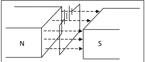
[image:24.612.239.446.586.667.2]When a conductor carries a current, it will be surrounded by a magnetic field. From Figure 2.4, the current is flowing into the page; therefore the circular lines of force have the direction as shown in.
Figure 2.4: Magnetic field due to magnet and current carrying conductor
N S
N S