START STOP SYSTEM
MOHD KHAIRUR RAHIM BIN AWANG
START STOP SYSTEM
MOHD KHAIRUR RAHIM BIN AWANG
This report submitted in partial fulfillment of the requirements for the award of a Bachelor of Mechanical Engineering (Automotive)
Faculty of Mechanical Engineering Universiti Teknikal Malaysia Melaka
i PENGAKUAN
Saya menngisytiharkan kerja dan perkataan kenyataan yang diggunakan didalam laporan ini adalah hasil kerja saya dan setiap butir maklumat yang diggunakan telah diberi peningiktirafan kepada penulis asal dan telah dijelaskan sumbernya.
ii PENGHARGAAN
Dengan ini saya mengambil kesempatan untuk mengucapkan jutaan terima kasih kepada ibu bapa saya yang sentiasa member bantuan dan dorongan untuk menjalani Projek Sarjana Muda ini. Tidak dilupakan kepada abang dan kakak saya juga yg turut membantu.
Yang dihormati Penasihat Projek Sarjana Muda saya, Dr Noreffendy Tamaldin yang banyak membantu, member tunjuk ajar kepada saya untuk menyempurnakan projek ini.
iii ABSTRACT
iv ABSTRAK
v TABLE OF CONTENT
APPRECIATION i
ABSTRACT iv
ABSTRAK v
TABLE OF CONTENT vi
LIST OF TABLE viii
LIST OF FIGURES xi
LIST OF SYMBOLS ix
CHAPTER 1 INTRODUCTION
1.1 Problem statement 2
1.2 Objektif 2
1.3 Scope 3
CHAPTER 2 LITERATURE REVIEW
vi 2.2.1 Four stroke spark ignition system 5
2.2.2 Engine cylinder geometry 7
2.2.3 Otto cycle 9
2.3 Ignition 10
2.3.1 Function of the ignition system 10
2.3.2 Basic igniton system 12
2.3.3 Spark plug 14
2.4 Fuel Injection 16
2.4.1 Fuel injection 16
2.4.2 Injection in SI engines 17
2.5 Emission 19
2.5.1 Global warming 19
2.5.2 Type of emission and pollutant 19
2.5.3 Exhaust emission 21
2.6 Fuel consumption 22
CHAPTER 3 METHODOLOGY 25
3.1 Project Overview 25
3.2 Project Flow 26
3.3 GT-POWER 27
3.3.1 GT-POWER procedure 27
3.3.2 Variable 30
vii
CHAPTER 4 - RESULTS 34
CHAPTER 5 – DISCUSSION 44
CHAPTER 6 – CONCLUSION AND RECOMMENDATION 47
REFERENCE 48
viii LIST OF TABLE
NO. TITLE PAGE
ix LIST OF FIGURES
NO. TITLE PAGES
2.2.1.1 Operation of the engine on four stroke cycle 6
2.2.2.1 Basic terminology 7
2.3.1 P-V diagram of Otto cycle 9
2.2.3.2 T-S diagram of Otto cycle 9
2.3.1.1 Increasing speed, ignition must start earlier 12 2.3.3.1 Battery or coil ignition system diagram 13
2.3.4.1 The diagram of spark plug 14
2.4.1.1 The drawing of the fuel injector Bosch 17 2.4.2.1 The location of injection nozzle in SI engines 19 2.5.3.1 Emission as a function of Equivalence Ratio for an SI engine 22 2.6.1 The example of engine performance of the car 23 2.6.2 The air fuel ratio of the engine 24
3.2.1 concept of flow chart 26
3.3.1.1 Workspace of GT-POWER software 28
x
3.3.3.1 workspace of GT-POST 32
4.1 Engine speed versus fuel flow for 30.4mm diameter and 33 75mm of length
4.2 show engine speed (rpm) versus brake specific CO 34 (g/kW-h) for diameter 30.4mm and 75mm of length
4.3 shows the engine speed (rpm) versus fuel flow 35 (kg/h) for 28 mm of diameter and 75 mm of length
4.4 shows the engine speed versus brake specific CO 36 for 28 mm of diameter and 75 mm lengths.
4.5 shows engine speed versus fuel flow for 30.4mm of 37 diameter and 72mm of length
4.6 shows engine speed versus brake specific CO 38 for 30.4mm of diameter and 72mm of length.
4.7 shows engine speed versus fuel flow for 28mm 39 of diameter and 72 mm of length
xi LIST OF APPENDIX
NO. TITLE PAGES
A SHOWS MODEL OF 4 CYLINDER ENGINE IN 50
GT POWER
1 CHAPTER 1
INTRODUCTION
1.0 INTRODUCTION
Internal combustion engine are widely use all over the world. Internal combustion engines is where the combustion takes place within the engine. (Ganesan, 2004). Internal combustion engines uses hydrocarbon compounds such as gasoline as a source of energy to move the vehicles. the internal combustion engines which convert chemical energy from gasoline into the mechanical energy to give energy for car to move. However, the products that been produced for example exhaust gas were not good for environmental.
2
To prevent and reducing the emission, engineer all around the world begin their researching to reduce emission that been produce by the passenger car. It been known that catalytic converter is the most effective devices for controlling exhaust emissions. In the past, lots of ways that been use for example auxiliary air injection, exhaust gas recirculation and positive crankcase ventilation. But by using this way, it will effect the power produce and consume lots of fuel. Since the catalytic converter was been introduced, the fuel consumption can be reduce too.
1.1 PROBLEM STATEMENT
A mixture of fuel and air that ready to be burn are waiting for the spark plug to plug some fire and ignite the mixture to produce power in the engine. Spark plug is one of the essential parts in the engine cylinder to make sure the combustion process occur smoothly. The challenge was to control the spark plug whether to turn it on or off so the combustion doesn’t occur in order to reduce the fuel consumption.
For gasoline engine, the fuel injection that been use was indirect injection which is low pressured time injection. The fuel injection function to inject the fuel before the valve and to maintain 14.7 : 1 ratio in the combustion chamber. By adjusting the timing of the injection, rich or lean mixture can be produced to vary the performance of the engine.
1.2 OBJECTIVE
3
engine management system to activate and deactivate the engine cylinders,
1.3 SCOPE
The scope of the research was :
1. To improve the fuel consumption of the vehicles. 2. To reduce the emission produce by the vehicles.
4 CHAP 2
LITERATURE REVIEW
2.1 HISTORY OF THE INTERNAL COMBUSTION ENGINE
The first Internal Combustion engine was developed by a French guy name J.J.E. Lenoir (1822 – 1900) in the year 1860. Back then coal gas and air mixture were drawn into the engine cylinder during 1st half of the stroke then being ignited by a spark. Pressure rises and the product of the combustion delivered the power to piston in the second half of the stroke. Then on the return stroke, the cylinder discharged the gases from it. It was possible to do return stroke by using a large flywheel which stored energy during the power stroke and dissipated energy during the return stroke.
5
de Rochas could not build the engine himself based on his principal, then Nicolaus August Otto built an engine based on these principal. The engine basically work on four stroke principal which are intake, compression, expansion or power and exhaust strokes. Otto had achieved great achievement by reducing the weight of the engines and volume and also give higher thermal efficiency.
By the 1880s, Dugald Clerk and James Robson of the UK and Karl Benz of Germany developed the two stroke internal combustion engine. In 1885, James Atkinson of England developed and engine with an expansion stroke larger then compression stroke. In 1882, Rudolf Diesel (1858 – 1913) build a different type of engine which a high compression ratio was used to ignite a fuel. (H.N. Gupta, 2006)
2.2 THE WORKING PRINCIPAL OF ENGINES
Using small spark to ignite the combustion in combustion chamber which give power to the engine. Using this principle, lots of type engine produced such four stroke cycle, and many more.
2.2.1 FOUR STROKE SPARK IGNITION ENGINE
6
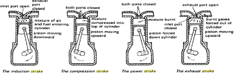
Figure 2.2.1.1 Operation of the engine on four stroke cycle Sources : (V.A.W Hillier, 2004)
a) Intake – the process where the piston are moving from TDC (top dead centre) to BDC (bottom dead centre) of the cylinder making some space for the air fuel mixture to enter the chamber. In this process the inlet valve will open and then the exhaust will closed so no air fuel mixture escape from the chamber.
b) Compression – process where the piston move from BDC to TDC to compress the mixture. Both inlet and exhaust valve were close. The mixture were placed at the clearance volume where the combustion will take part later.
c) Power – during the power stroke, both valve also closed. The spark plug will ignite the mixture, and then the mixture will burn and give power to force the piston move towards BDC. Great change in pressure and temperature occur during this process.
7
[image:20.595.128.485.167.312.2]2.2.2 ENGINE CYLINDER GEOMETRY
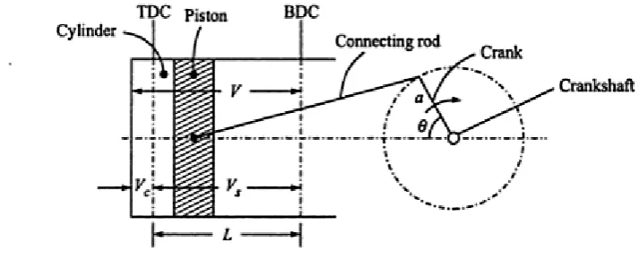
Figure 2.2.2.1 Basic terminology
a) Bore (d) – the inside diameter of the engine cylinder. Bore name come from the process of manufacturing using the boring process
b) Stroke (L) – during the travel of the piston, there is an upper as well as lower limiting position at which the direction of the motion is reversed. The linear distance through which the piston travels between the extreme upper and lower position of the piston is called the stroke. Stroke is equal two time crank radius.
L = 2a ( equation 2.1)
Where a = crank length L = stroke length
c) Top Dead Centre – the position where the piston will travel to the topmost position. This is where the piston is at the farthest from the crankshaft.
8
e) Clearance Volume, – the position when the piston at the TDC, the trapped air is contained at the top part of the cylinder called clearance volume. The piston cannot reach this place. This place always clear.
f) Piston Displacement, – the volume displaced from the position of TDC to BDC,
= L (equation 2.2) Where,
d = bore L = stroke
e) Cylinder volume, V – includes both the clearance volume and swept volume
V = + (equation 2.3)
f) Compression Ratio, r – ratio of the total cylinder volume to clearance volume
R = (equation 2.4)
9 2.2.3 OTTO CYCLE
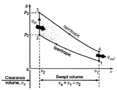
Figure 2.2.3.1 shows the P-V diagram of Otto cycle ( source : M. Ratore, 2010)
Figure 2.2.3.2 shows the T-S diagram of Otto cycle ( source : M. Ratore, 2010)
10
The thermal efficiencies is important to show how good the engine can perform. The thermal efficiencies for the Otto cycle is
=
(equation 2.5)
Where ;
= m ( ) (equation 2.6)
= m ( ) (equation 2.7)
2.3. IGNITION SYSTEM
Ignition is very important in order to have a combustion to started. For spark ignition engines, using electrical discharge to produce the spark between two electrode.
2.3.1 Function Of The Ignition System
11
1. Spark production – the ignition system must be able to quickly build enough high voltage sufficient to satisfy the requirements to ignite the air fuel mixture and maintain the adequate burn time for complete combustion. 2. Spark timing control – the ignition system must be able to alter the delivery
time of the spark to account for rpm, varying load, and demand conditions.
3. Spark distribution – the ignition system must be able to deliver spark to the correct cylinder at the right time during the compression stroke in order to begin the combustion process.
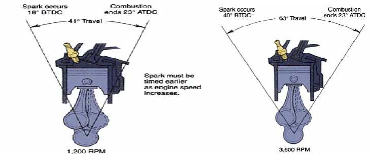
[image:24.595.141.507.509.663.2]4. After the combustion take place, strong pressure force the piston to do power stroke so the piston move from TDC towards BDC. In order to achieve the maximum pressure for the combustion, the piston position should be 10 degrees or 20 degrees after top dead center (ATDC) (source : Ken Pickeril, 2010). This is because the combustion of air fuel mixture take some time and the combustion must occur before the piston is on power stroke. Then the spark should ignite before the piston reach the TDC so the combustion can occur. As increasing in speed, the ignition occur need to ignite earlier. Figure 2.3.1.1 shows differ in angle in differ speed.