AUTOMATIC ROOM TEMPERATURE CONTROLLER
ABD. HALIM BIN ZAKARIA
This report is submitted in partial fulfillment of the requirements for the award of Bachelor of Electronic Engineering (Industrial Electronics) With Honours
UNIVERSTI TEKNIKAL MALAYSIA MELAKA
FAKULTI KEJURUTERAAN ELEKTRONIK DAN KEJURUTERAAN KOMPUTER
BORANG PENGESAHAN STATUS LAPORAN
PROJEK SARJANA MUDA II
Tajuk Projek : AUTOMATIC ROOM TEMPERATURE CONTROLLER
Sesi
Pengajian : 2008/2011
Saya ………...ABD. HALIM BIN ZAKARIA………..……..
mengaku membenarkan Laporan Projek Sarjana Muda ini disimpan di Perpustakaan dengan syarat-syarat kegunaan seperti berikut:
1. Laporan adalah hakmilik Universiti Teknikal Malaysia Melaka.
2. Perpustakaan dibenarkan membuat salinan untuk tujuan pengajian sahaja.
3. Perpustakaan dibenarkan membuat salinan laporan ini sebagai bahan pertukaran antara institusi
pengajian tinggi.
4. Sila tandakan ( √ ) :
SULIT*
(Mengandungi maklumat yang berdarjah keselamatan atau kepentingan Malaysia seperti yang termaktub di dalam AKTA RAHSIA RASMI 1972)
TERHAD* (Mengandungi maklumat terhad yang telah ditentukan oleh organisasi/badan di mana penyelidikan dijalankan)
TIDAK TERHAD
Disahkan oleh:
__________________________ ___________________________________
(TANDATANGAN PENULIS) (COP DAN TANDATANGAN PENYELIA)
Alamat :113, LORONG SMK SEMERAH, 83600
SEMERAH BATU PAHAT JOHOR.
iii
“I hereby declare that this report is the result of my own work except for quotes as cited in the reference”
iv
“I hereby declare that I have read this report and in my opinion this report is sufficient in terms scope and quality for the award of Bachelor of Electronic
Engineering (Industrial Electronics) With Honours”
Signature : ………
Name : ENGR. FAKRULRADZI BIN IDRIS
v
vi
ACKNOWLEDGEMENTS
vii
ABSTRACT
viii
ABSTRAK
ix
CONTENTS
CHAPTER TITLE PAGES
PROJECT TITLE i
DECLARATION FORM DECLARATION
ii iii
SUPERVISOR DECLARATION iv
DEDICATION v ACKNOWLEDGEMENT vi ABSTRACT ABSTRAK vii viii CONTENT ix
TABLE LIST xiii
FIGURE LIST xiv
ABBREVIATIONS LIST xvi
APPENDIX LIST xvii
I INTRODUCTION
1.1 Project Background 1
1.2 Project Objective 1
1.3 Problem Statement 2
1.4 Scope of Work 2
II LITERATURE REVIEW
x
2.2 Reference Circuit 1 4
2.3 Reference Circuit 2 6
2.4 Reference Circuit 3 8
2.5 Reference Circuit 4 9
2.6 Reference Circuit for PSM Project 11
2.7 Microcontroller 13
2.7.1 Memory 13
2.8 Introduction to PIC Microcontroller 14
2.9 Temperature Sensor (LM35DZ) 16
III PROJECT METHODOLOGY
3.1 Flow Chart Methodology 18
3.2 Identify the Title 21
3.3 Searches for Information 21
3.4 Understanding Basic Matter of Project 21
3.5 Identify the Circuits and Buy Electronic Components
21
3.6 Develop Program for PIC 3.6.1 MPLAB IDE Compiler
22 23 3.7 Circuit Simulation and PCB Design
by Proteus 7 Professional
25
3.8 Circuit Construction on Breadboard 27
3.9 Circuit Construction on PCB and Integration to Prototype
27
IV PROJECT’S CIRCUIT OPERATION
4.1 General Description 29
xi
4.3 Power Transistor (BD135) 32
4.4 PIC16F876A (Microcontroller) 32
4.5 Interface PIC16F876A with Temperature
Sensor (LM35)
34
4.6 Interface PIC16F876A with LCD
(2X16 character)
34
4.7 Power Supply for Circuit 35
4.8 ICSP for Programming PIC Microcontroller 36
IV PROJECT’S CIRCUIT OPERATION
4.9 Push Button as Input for PIC microcontroller 37
4.10 LED as Output for PIC Microcontroller 37
4.11 Interface PIC16F876A with DC Brushless Fan 38
4.12 Software / Source Code 38
V RESULT
5.1 Expected result 40
5.2 Obtained Result
5.2.1 Software Result
5.2.2 Hardware Result
41 41
44
5.3 Hardware Development 48
5.4 Software Programming 49
VI CONCLUSION AND RECOMMENDATION
6.1 Conclusion 50
6.2 Recommendation 51
xii
xiii
TABLE LIST
TABLE TITLE PAGES
2.1 Component list for the circuit 4
4.1 Pin description regarding to Figure 4.5 32
xiv
FIGURE LIST
FIGURE TITLE PAGES
2.1 Temperature Controlled Auto Fan [1] 4
2.2 Automatic Temperature Controlled Fan 6
2.3 Temperature Monitoring Control System 8
2.4 Automatic Temperature Controlled Fan 9
2.5 Automatic Temperature Controlled Fan 11
2.6 PIC burner 15
2.7 PIC16F876A 16
2.8 LM35DZ schematic diagram 16
3.1 Flowchart of project methodology 19
3.2 Continue from flowchart of project methodology 20
3.3 Several components that related to circuit project 22
3.4 3.5
Process of communication between man and a PIC MP LAB IDE Desktop
23 24
3.6 Circuit design with the ISIS 7 Professional 26
3.7 3.8
3.9
PCB Design with ARES 7 Professional Circuit Construction on Breadboard
Complete Prototype
26 27
28
4.1 Block diagram for the circuit 30
4.2 Circuit Diagram 30
4.3 Connection for LM35 31
4.4 Pin position for LM35 31
xv
4.6 PIC16F876A 33
4.7 LCD (2X16 character) 34
4.8 Schematic of the LCD display 35
4.9 Power supply circuit 36
4.10 ICSP connection 37
4.11 Push button connection 38
4.12 LED connection 39
4.13 Flow chart of circuit operation 39
5.1 5.2
Programming in MPLAB IDE
Error Massage at Build Output Window
41 42
5.4 HEX Machine Code 43
5.5 Initial Result for the Simulation 43
5.6 Final Result for the Simulation 44
5.7 Initial Condition 45
5.8 Fan A and LED A Activated 45
5.9 Strobe Light and LED B activated 46
5.10 Fan A, LED A, Strobe Light and LED B Activated 46
5.11 Fan A, LED A, Strobe Light and LED B Dectivated 47
xvi
LIST OF ABBREVIATIONS
PCB - Printed Circuit Board
NTC - Negative Temperature Coefficient
AC - Alternate Current (Arus Ulang Alik)
IC - Integrated Circuit
DC - Direct Current (Arus Terus)
LED - Light Emitting Diode
SCR - Silicon Controlled Rectifier
ADC - Analog Digital Converter
PIC - Programmable Interface Circuit
xvii
APPENDIX LIST
APPENDIX TITLE PAGES
A PIC16F876A Data sheet 54
B LM35DZ temperature sensor Data sheet 58
C COMPONENTS PRICE ESTIMATION 61
D Source Code 62
1
CHAPTER I
INTRODUCTION
1.1 PROJECT BACKGROUND
Room temperature (also referred to as ambient temperature) is a common term to denote a certain temperature within enclosed space at which humans are accustomed. Room temperature is thus often indicated by general human comfort, with the common range of 22°C (71.6 °F) to 28°C (82.4 °F), though climate may acclimatize people to higher or lower temperatures. For human comfort, desirable room temperature greatly depends on individual needs and various other factors. Because of changing effect of temperature, an automatic control room temperature is needed to solve the problem of uncomfortable for human life.
1.2 PROJECT OBJECTIVES
Due to the problem statement, it’s cleared that the objectives of the project is:
1. To design an accurate and sensitive circuit to control the room’s temperature according to any changes of temperature. The suitable reference temperature is in the range of 22°C to 28°C.
2
1.3 PROBLEM STATEMENTS
Room temperature always changes and sometimes it occurs drastically (for example: rainy day at the night). Thus, uncomfortable environment will be happen to the human life. Secondly, human aided control are commonly use but in certain time there are some unexpected matter occur. For this reason, automatic control system is needed. Another that the circuit of automatic control room temperature previously is less stable and less sensitive. Thus the measurement temperature of the circuit is also not accurate.
1.4 SCOPES OF WORK
3
CHAPTER II
LITERATURE REVIEW
2.1 Introduction
Literature Review is important in each project as a base for gathering information necessary to complete the project. All information is gathered from various sources such
as:-1. Journal 2. Books
3. Conference Transcript 4. Thesis
5. Patent 6. Website
4
[image:21.595.117.513.129.385.2]2.2 Reference Circuit 1
Figure 2.1 Temperature Controlled Auto Fan [1]
Table 2.1 Component list for the circuit
Part Description Notes
IC1 LM741 Op-Amp NE741,µA741, etc.
Q1 2N2222A transistor See text
D1 1N4148 Diode 1N4001, or others
Th1 50K Thermistor KC005T in prototype
Re1 12V Relay RS is 1A
R1 15K, 5% resistor brown-green-orange
R2,R5 10K, 5% resistor brown-black-orange
R3 150K, 5% resistor brown-green-yellow
R4 4K7, 5% resistor yellow-purple-red
R6 1K, 5% resistor brown-black-red
R7 1K8, 5% resistor brown-gray-red
P1 100K Trimmer Pot Bourns
C1 10uF/25V Capacitor Electrolytic
C2 0.01uF, Capacitor Ceramic
[image:21.595.172.469.452.756.2]5
Figure 2.1 show a circuit of Temperature Controlled Auto Fan design by Tony Van Roon [1]. This circuit uses one temperature sensor, thermistor 48K made by Fenwal (#197-503LAG-A01). This 48K was measured at exactly 25°C and with 10% tolerance. The resistance increases as the surrounding temperature decreases. Another name for this thermistor is 'NTC'. NTC stands for "Negative Temperature Coefficient" which means when the surrounding temperature decreases the resistance of this thermistor will increase. P1 is a regular Bourns trimmer and adjusts a wide range of temperatures for this circuit. R1 is a 'security' resistor just in case the trimmer pot P1 is adjusted all the way to '0' ohms. At which time the thermistor would get the full 12 volt and it will get too hot [1].
The function of R3 is to feeds a bit of hysteresis back into the op-amp to eliminate relay 'chatter' when the temperature of the thermistor reaches its threshold point. Depending on which application and the type to use for Q1 and Re1, start with 330K or so and the value is adjusted it’s downwards until it satisfied. The value of 150K shown in the diagram worked for this circuit. Decreasing the value of R2 means more hysteresis, just don't use more then necessary. Or temporarily use a trimmer pot and read off the value. In this case 120K is suitable fot this circuit. Transistor Q1 can be a 2N2222(A), 2N3904, NTE123A, and ECG123A. Not critical at all. It acts only as a switch for the relay so almost any type will work, as long as it can provide the current needed to activate the relay's coil [1].
6
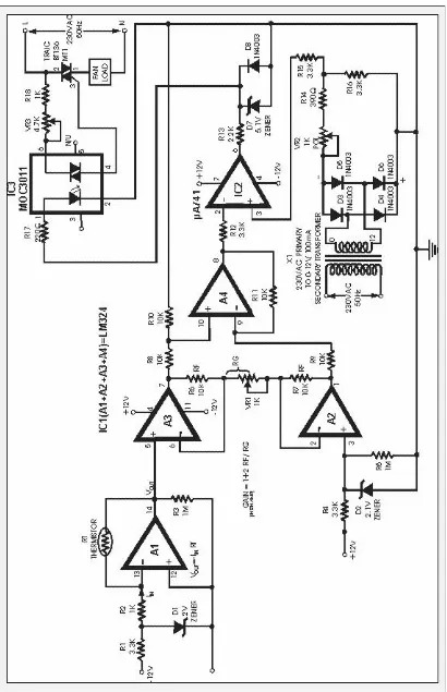
[image:23.595.110.520.102.737.2]2.3 Reference Circuit 2
7
Here (Figure 2.2) is a circuit through which the speed of a fan can be linearly controlled automatically, depending on the room temperature. The circuit is highly efficient as it uses thyristors for power control. Alternatively, the same circuit can be used for automatic temperature controlled AC power control. In this circuit, the temperature sensor used is an NTC thermistor, i.e. one having a negative temperature coefficient. The value of thermistor resistance at 25°C is about 1 kilo-ohm. Op-amp A1 works as current-to-voltage converter and converts temperature variations into
voltage variations. Other side,Op-amps A2, A3 and A4 work as an instrumentation
amplifier to amplify the change in voltage due to change in temperature [2].
The combination of resistor R2 and diode D2 is used for generating reference voltage as we want to amplify only change in voltage due to the change in temperature. Op-amp µA741 (IC2) works as a comparator. One input to the comparator is the output from the instrumentation amplifier while the other input is the stepped down, rectified and suitably attenuated sample of AC voltage. IC2 also functions as a pulse width modulator in this circuit. The output from the comparator is coupled to an optocoupler, which in turn controls the AC power delivered to fan (load) [2].
![Figure 2.1 Temperature Controlled Auto Fan [1]](https://thumb-us.123doks.com/thumbv2/123dok_us/138763.15907/21.595.172.469.452.756/figure-temperature-controlled-auto-fan.webp)