3D MILLING MACHINE USING LEGO MINDSTORM
FERLAND KARSHIFF SIRINUS
3D MILLING MACHINE USING LEGO MINDSTORM
FERLAND KARSHIFF SIRINUS
This report is submitted
in fulfillment of the requirement for the degree of Bachelor of Mechanical Engineering (Design and Innovation)
Faculty of Mechanical Engineering
UNIVERSITI TEKNIKAL MALAYSIA MELAKA
i
DECLARATION
I declare that this project report entitled “3D Milling Machine Using LEGO
Mindstorm” is the result of my own work except as cited in the references
Signature : ...
Name : FERLAND KARSHIFF SIRINUS
APPROVAL
I hereby declare that I have read this project report and in my opinion this report is
sufficient in terms of scope and quality for the award of the degree of Bachelor of
Mechanical Engineering (Structure & Materials).
Signature :. ...
Name of Supervisor : DR. FAIZ REDZA BIN RAMLI
iii
DEDICATION
To my beloved mother and father
To my great supervisor and second examiner
To my fellow friends
ABSTRACT
Milling machine is a machine that can be operated in either manually or
automatically which implemented by CNC system. The milling machine can drill, slot
milling, end milling, face milling and bore milling any surfaces according to the
designed motor power. The milling machine consist of a moving x and y axis table,
milling arbor that holds the milling cutter and some more. For this project, a vertical
milling machine prototype will be made by using LEGO Mindstorm NXT and the
application of OpenStructure concept is applied. Investigation on the milled product
and operational time is recorded. Several conceptual design is made at first, then
continued with fabricating the machine and the Waterfall model is used to align with
the objectives that established. Finally, the results of the milled product is recorded
v
ABSTRAK
Mesin pengisar adalah mesin yang boleh beroperasi secara manual mahupun
automatik menggunakan sistem CNC. Mesin pengisar boleh menggerudi, melakukan
pengisaran slot, pengisaran hujung, pengisaran bidur, pengisaran permukaan dan
pengisaran gerigi pada mana-mana bahagian permukaan mengikut kesesuaian kuasa
motor. Mesin pengisar terdiri daripada meja yang boleh bergerak pada paksi x dan y
axis, punjung pengisar yang memegang pemotong pengisar dan lain-lain. Untuk
projek ini, mesin pengisar menegak dibina dengan menggunakan LEGO Mindstrom
NXT dan konsep OpenStructure digunakan. Pada permulaan, beberapa rekabentuk
konsep dijalankan, kemudian fabrikasi dilakukan dan konsep model Waterfall
digunakan supaya selari dengan objektif-objektif yang telah disediakan. Akhir sekali,
hasil keputusan daripada produk pengisaran direkodkan dan dibentangkan serta
ACKNOWLEDGEMENT
I would like to express my deepest appreciation to my supervisor Dr. Faiz
Redza Ramli for giving me this opportunity to do final year project with him. He never
hesitated to give me advice and guidance whenever I confronted problems. I am
thankful for his patience and advice while leading me in this project.
Secondly, I would like to thank my previous supervisor during internship
named Mr. Roland Tinjau Rusulan for spending his time to guide me. They would
share his knowledge in the field of machinist with me and guide me to do this project.
I would like to thank my course mates for giving me their support, patience
vii
CONTENT
CHAPTER CONTENT PAGE
SUPERVISOR’S DECLARATION ii
TABLE OF CONTENT iii
LIST OF FIGURES x
LIST OF TABLE xii
LIST OF EQUATIONS xiii
LIST OF ABBREVIATIONS xiv
CHAPTER 1 INTRODUCTION 1
1.1 Background 1
1.2 Problem Statement 4
1.3 Objective 4
1.4 Scope Of Project 5
CHAPTER 2 LITERATURE REVIEW
2.1 The Characteristic of a Milling Machine 6
2.2 LEGO Mindstorm as An Educational Method 6
2.3 Speed for Milling Cutters 7
2.4 The Servo Motor of LEGO Mindstorm NXT 8
2.5 Types of Milling Machine 10
2.6 Variants of Milling Machine
2.7 Computer Numerical Control Machines
11
12
CHAPTER 3 METHODOLOGY
3.1 Introduction 15
3.2 Investigation on Milling Machine Operations 15
3.3 Research on OpenStructures 16
3.4 Prototype Development 17
3.5 Design Through the Waterfall Model 18
CHAPTER 4
CHAPTER 5
DESIGN AND PROTOTYPE 4.1 Introduction
4.2 Movement of Axis based on LEGO Digital
Designer
4.2.1 Design of Body
4.2.2 Building using Lego Digital Designer
4.3 Comparison for the Prototype Milling Machine
4.4 LEGO Mindstorm Block Diagram Programs
4.5 The Prototype of 3D Milling Machine
4.5.1 Descriptions of Parts From Prototype
4.6 Calibrations of Block Diagram Programs
4.6.1 Flowchart Based on Waterfall Model
4.6.2 Calibrating Variables
RESULTS AND DISCUSSION 5.1 Introduction
5.2 Accuracy of the Prototype Milling Machine
5.2.1 L-shaped
5.2.2 Drilling
5.2.3 Slot
5.2.4 End Mill
5.8 Results and Operational Time Taken
5.9 Discussion
5.9.1 Introduction
5.9.2 Prototype of 3D Milling Machine using
ix
CHAPTER 6
5.9.3 Calibrations
5.9.4 Milling Operations and Product
CONCLUSION AND RECOMMENDATION
44
45
6.1 Conclusion
6.2 Future Research
REFERENCES APPENDICES
46
46
47
LIST OF FIGURES
Figures Descriptions Page
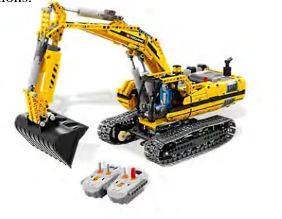
1.1 The 3Xcavator 2
2.1 The internal structure of LEGO Mindstorm NXT motor. 8
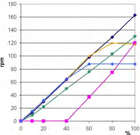
2.2 Comparison of motors with different loads and power
supplies.
8
2.3 Key legends for the comparison of motors with different loads
and power supplies.
9
2.3 The NXT motors versus applied load. 9
3.1 Geometrical grid of OpenStructures 16
3.2 (a) Parts of water dispenser made by OpenStructures. (b) An
assembled water dispenser made by using OpenStructures.
16
3.3 The early design of the 3D milling machine prototype 17
3.4 The Waterfall model. 18
4.1 The selected design based on the established objectives. 21
4.2 The user interface of LEGO Digital Designer 21
4.3 The digital X-axis of the prototype. 22
4.4 The digital Y-axis of the prototype. 22
4.5 The digital Z-axis of the prototype. 23
xi
4.7 The block diagram coding of the prototype milling machine. 27
4.8 The simple block program of making L shaped on the surface
of the flower foam.
28
4.9 (a) The milling operation of L shaped on the flower
foam. (b) The cutting tool reached the edge of the L and
continuously perform operations forward and reverse
directions.
29
4.10 (a) The top view of milled product which shows ‘L’
shaped.
(b) The side view of the milled product.
29
4.11 The finished prototype of 3D milling machine. 30
4.12 Top view of prototype. 31
4.13 Side view of prototype. 31
4.14 Simple flow chart of programmed block diagrams. 33
4.15 (a) Before calibrations (b) After calibrations. 34
4.16 Variables of motor B. 35
4.17 Additional of LOOP code and variables changed for motor B. 35
4.18 (a) First and trial error for straight milling (b) First trial and
error for the L shaped program.
36 4.19 4.20 4.21 4.22 4.23
(a) CATIA for L shaped (b) Product for L shaped.
(a) CATIA for drilling. (b) Product for drilling.
(a) CATIA for slot milling. (b) Product for slot milling.
(a) CATIA for end milling. (b) Product for end milling.
Prototype of 3D milling machine using LEGO Mindstorm and
LIST OF TABLE
Table Descriptions Page
4.1 Results of milled products. 25
4.2 The block diagrams. 26
4.3 Descriptions of parts of prototype. 32
xiii
LIST OF EQUATIONS
Equations Descriptions Page
1 Equation of speed, n 7
2 Cutting speed 25
3 Spindle speed 25
4 Feed 25
LIST OF ABBREVIATIONS
Abbreviations Descriptions Page
LEGO “Leg Godt” 1
NXT Next 1
CNC Computer Numerical Control 12
SK Steil Kegel 14
CAT Computer Aided Translation 14
BT Baron Taper 14
ISO International Organization for Standardization 14
HSK Hohl Shaft Kegel 15
NMTB National Machine Tool Builders Association 15
CHAPTER 1
INTRODUCTION
1.0 BACKGROUND
The function of a milling machines are to machine flat surfaces and produce
other irregular surfaces. Moreover, milling machines can also be used to bore, drill,
and produce slots which make the milling machine a very versatile machine. The
milling machine removes metal by using a rotating cutter that is fed into a moving
work piece. Milling machine have a spindle that can be fed in z-axis with a quill feed
lever on the machine head. Furthermore, the bed of the milling machine can be
controlled manually which will move the work piece in x, y and z axes. The given
material must match the cutting tool with a specific cutting forces and should be kept
constant.
The LEGO Mindstorms are a series of kits which combines software and
hardware which gives the LEGO Mindstorm the ability to produce or innovate a
customizable and programmable robot with various kind of usage. The first generation
of the LEGO Mindstorm kit are known as the Robotics Invention System (IRS) and
then replaced by the new generation namely LEGO Mindstorm NeXT, which is then
officially renamed as LEGO Mindstorm NXT in 2006. The LEGO Mindstorm NXT
was created and developed at the Massachusetts Institute of Technology Media Lab
along with a programmable brick called NXT Intelligent Brick. Since then, LEGO
Mindstorms NXT are widely used at all educational level which is lead it to be divided
to learn easier in the basic programming through the visual element without having to
face complicated problems and syntax errors.
The LabView Software for the LEGO Mindstorm NXT is free and
downloadable from the official website of the LEGO Mindstorm. Each parts of the
LEGO are connected by using joints provided and then the electrical power from the
motor are converted into mechanical power that is transferable through a series of
connection of mechanical system. In spite of that, the LEGO Mindstorm NXT also
have other elements to be program at specific stimuli part such as light sensor and
sound sensor. The combinations of stimuli parts and compiled program into the
intelligent brick would be able to create a programmable robot. For instance,
3Xcavator as shown in Figure 1. The model of the LEGO are able to be controlled
independently by the user through direct programming or even using third party tools
such as Bluetooth connections.
LEGO Mindstrom NXT able to be applied in our surrounding especially in the
field of engineering. In this project, a 3D milling machine will be developed by using
the LEGO Mindstorm NXT as the brain. A series of programming will be applied in
the intelligent bricks to rotate the tool bit of the milling machine at certain rate of
rotation per minute (RPM) which could be match to the RPM of the milling machine.
An example of the applications of LEGO Mindstorm NXT in manufacturing a product
is the Arthur Sacek’s Milling Machine which use a tool bit to make a product base on
a converted drawings. Another examples that applies the same principle are the
[image:18.612.250.448.356.510.2]MakerLEGOBot. However, the MakerLEGOBot did not use the concept of 3D
printing but rather only assemble a series of LEGO bricks into a product base on the
script of programming inside the intelligent brick.
Also in this project, the design and concept of OpenStructures will be applied
which will be the body of the milling machine. The OpenStructures is a project that
explores the possibility to construct a model where anyone design are downloadable
from the OpenStructures official website which the designs are based on a shared
geometrical grid. The geometrical grid act as a medium to connect people throughout
the world through simple designs. It initiates a collaborative responds which everyone
can contribute in parts, components, design and structures. Furthermore, the
OpenStructures is an ongoing experiments that to determine the possibility of sharing
design projects according to a shared modular grid, which is the open standard that
The usage of LEGO Mindstorm NXT in the prototype of a milling machine
would encounters its quantity and quality. The LEGO Mindstorm set of bricks contains
a limited set and amounts of item for a package, and have a limited spaces for
mechanical system, such as the gearing system. The intelligent bricks used battery as
its life support which gives a limited amount of time. Moreover, as the battery slowly
to become low, the quality of the product produced by the milling machine prototype
would be also low. If the brick were charged during the operational time, it might lead
to a short circuit of the inside circuit of the brick and damage it. Even though using the
LEGO Mindstorm NXT could make the milling machine to be useful at anywhere and
anytime, it still not as efficient as a fixed milling machine because of different surfaces
of the working table. The OpenStructure are using a geometrical grid, which have a
limited range from one grid to another. This could lead to the extension of the 3D
milling machine part. To this date that this report was written, there are no 3D milling
machine that used the concept of the OpenStructures.
1.3 OBJECTIVES
The list below are the objectives established as a guideline when working on
this project:
1. To analyse the milling machine operational process.
2. To investigate and analyse the 3D milling machine using LEGO Mindstorm
NXT.
3. To build a prototype of 3D milling machine using OpenStructures concept by
1.4 SCOPE OF PROJECT The scope of this project are:
1. The concept of the milling machine will only covers on the basic milling
machine that is the vertical milling machine and will be implemented on the
design.
2. The LEGO Mindstorm NXT intelligent brick will be the brain of the prototype
of the milling machine which will first be demonstrated in a simple gearing
system.
CHAPTER 2
LITERATURE REVIEW
2.1 THE CHARACTERISTIC OF A MILLING MACHINE
The milling machine consists of base, overarm, spindle, column, table and
knee. Each part have their own function that completed the characteristic of a basic
and simple milling machine. Another important part are the tool bit, which is the
milling machine cutter. The Xi’an Jiaotong University research team (Zhao et, 2008)
states that; ‘The precision and reliability of machine tools directly influence the
processing quality, productivity and efficiency, and further the market competitiveness
and the user’s confidence’. This means that the tool bit plays an important role to
produce a product with a good quality. The application of the milling machine in
flexible and agile manufacturing, and remanufacturing of a product has steadily on the
rise which a compaction of the whole structures would make it more economical
(Xuxiao, 2010).
2.2 LEGO MINDSTORM NXT AS AN EDUCATIONAL METHOD
The choice of an appropriate platform of using educational robotics activities
are important nowadays. Some requirements for the medium to be used in the
educational robotics are the ability to program the medium at different level of
complexity and supports programming paradigms, able to be exploited at any level of
NXT have all the requirements stated. Harel and Papart (1991) states that; ‘The NXT
complies very well with the constructionist learning approach and the robot is a public
entity’. The LEGO Mindstorm NXT have their own advantages in the educational
level and one of it is to move students to the second step of robotics and automation
educational in a quick process.
2.3 SPEED FOR MILLING CUTTERS
The speed of milling is the distance at which the circumference of the cutter
passes over the work piece. The RPM of the spindle is necessary to give a desired
speed which depends on the size of the milling cutter. The speed is determined by the
kind of material being cut and the size and type of the tool bit used, width and depth
of the cut, finish required, type of cutting fluid and method of application, and power
and speed available are factors need to be considered.
The speed computation for choosing the tool bit are show as follow.
RPM =
Where,
RPM = Speed of the spindle (in revolutions per minute)
CS = cutting speed of milling cutter.
D = diameter of milling cutter.
For examples, the spindle speed for machining a piece of steel at a speed of 35 with a
cutter 2 inches in diameter is calculated as follow.
RPM =
70 RPM
The servo motor of the LEGO Mindstorm NXT runs at 170 RPM with no load
and draws 60 mA of power. This means that the increase of the power draw in turn
provides more torque. However, when a load is put, the servo will run slower but draws
more current. Therefore, a hypothesis is established that the intelligent bricks will run
out of powers before it finished a work. Figure 2.0 shows the internal structure of the
LEGO Mindstorm.
Figure 2.0. The internal structure of LEGO Mindstorm NXT motor.
Throughout the researches, the comparison of motors with different type of loads and
power supplies are done. Figure 3 shows the result of the comparison.
[image:24.612.195.463.209.350.2] [image:24.612.212.439.426.645.2]