Original Citation
Ford, Derek G., Myers, Alan, Haase, Frerk, Lockwood, Stephen and Longstaff, Andrew P. (2013)
Active Vibration Control for a CNC Milling Machine. Proceedings of the Institute of Mechanical
Engineering Part C, Journal of Mechanical Engineering Science. ISSN 0954-4062
This version is available at http://eprints.hud.ac.uk/17797/
The University Repository is a digital collection of the research output of the
University, available on Open Access. Copyright and Moral Rights for the items
on this site are retained by the individual author and/or other copyright owners.
Users may access full items free of charge; copies of full text items generally
can be reproduced, displayed or performed and given to third parties in any
format or medium for personal research or study, educational or not-for-profit
purposes without prior permission or charge, provided:
•
The authors, title and full bibliographic details is credited in any copy;
•
A hyperlink and/or URL is included for the original metadata page; and
•
The content is not changed in any way.
For more information, including our policy and submission procedure, please
contact the Repository Team at: [email protected].
http://pic.sagepub.com/content/early/2013/04/04/0954406213484224
The online version of this article can be found at:
DOI: 10.1177/0954406213484224
online 4 April 2013
published
Proceedings of the Institution of Mechanical Engineers, Part C: Journal of Mechanical Engineering Science
Derek Gwynne Ford, Alan Myers, Frerk Haase, Stephen Lockwood and Andrew Peter Longstaff
Active Vibration Control for a CNC Milling Machine
Published by:
http://www.sagepublications.com
On behalf of:
Institution of Mechanical Engineers
can be found at: Science
Proceedings of the Institution of Mechanical Engineers, Part C: Journal of Mechanical Engineering Additional services and information for
http://pic.sagepub.com/cgi/alerts Email Alerts: http://pic.sagepub.com/subscriptions Subscriptions: http://www.sagepub.com/journalsReprints.nav Reprints: http://www.sagepub.com/journalsPermissions.nav Permissions:
What is This?
- Apr 4, 2013
OnlineFirst Version of Record
Active vibration control for a CNC
milling machine
DG Ford, A Myers, F Haase, S Lockwood and A Longstaff
Abstract
There is a requirement for improved three-dimensional surface characterisation and reduced tool wear when modern computer numerical control (CNC) machine tools are operating at high cutting velocities, spindle speeds and feed rates. For large depths of cut and large material removal rates, there is a tendency for machines to chatter caused by self-excited vibration in the machine tools leading to precision errors, poor surface finish quality, tool wear and possible machine damage. This study illustrates a method for improving machine tool performance by understanding and adap-tively controlling the machine structural vibration. The first step taken is to measure and interpret machine tool vibration and produce a structural model. As a consequence, appropriate sensors need to be selected and/or designed and then integrated to measure all self-excited vibrations. The vibrations of the machine under investigation need to be clearly understood by analysis of sensor signals and surface finish measurement. The active vibration control system has been implemented on a CNC machine tool and validated under controlled conditions by compensating for machine tool vibrations on time-varying multi-point cutting operations for a vertical milling machine. The design of the adaptive control system using modelling, filtering, active vibration platform and sensor feedback techniques has been demonstrated to be successful.
Keywords
Adaptive vibration control, milling, surface finish, structural vibration model, static/dynamic testing
Date received: 9 October 2012; accepted: 12 February 2013
Background
Machining and machine tool errors
Ford1 proposed that the design process of any high precision computer numerical control (CNC) machine tool in order to achieve an ever increasing demand for greater accuracy and therefore a more stringent performance specification must embrace error avoid-ance, error measurement and error compensation techniques. He postulated that the measurement of the repeatable time and spatial errors can allow com-pensation methods to be applied to the machine for correction of those errors provided sufficient reso-lution has been allowed for in the design, and that the absolute limit on accuracy for a particular machine is set by its measured repeatability figures. He stated that the three main areas of concern affecting compo-nent accuracy are environmental effects, user effects and the machine tool static and dynamic accuracy. He stated that sources of error confined to a 3-axis machine tool are the geometrical inaccuracies (21 errors caused by the pitch, yaw and roll of the axes and the squareness between the axes), thermally induced errors (causing thermal structure distortion)
and the load errors (causing the machine structure to strain and deform).
Lui et al.2 emphasised that the control of the machining errors for a milling machine needs the understanding of the process for peripheral milling and face milling. Fischer3 illustrates the mechanics of metal cutting for use with multi-tool point oper-ations. Tlusty4provided the knowledge base for pre-vious cutting process modelling consideration, and Tlusty and Polacek5provided the knowledge base fol-lowing their investigations into the cutting process dynamics. Tobias6a pioneer in experimental machine vibration and analysis concluded that there are three basic types of vibrations experienced by machine tools: (a) free or transient vibrations resulting from impulses transferred to the structure, where the
Centre of Precision Technologies, University of Huddersfield, Huddersfield, UK
Corresponding author:
DG Ford, Centre of Precision Technologies, University of Huddersfield, Queensgate Huddersfield HD1 3DH, UK.
Email: [email protected]
Proc IMechE Part C:
J Mechanical Engineering Science
0(0) 1–16
!IMechE 2013 Reprints and permissions:
sagepub.co.uk/journalsPermissions.nav DOI: 10.1177/0954406213484224 pic.sagepub.com
structure is deflected and oscillates in its natural modes of vibration until the damping present in the structure causes the motion to die away; (b) forced vibrations resulting from periodic forces within the system. The machine tool will oscillate at the forcing frequency and if this frequency corresponds to one of its natural frequencies of the structure, the machine will resonate in the corresponding natural mode of vibration and (c) self-excited vibrations, usually resulting from the dynamic instability of the cutting process. Kalmar-Nagy et al.7 stated that one of the most important effects causing poor surface quality in a cutting process is vibration arising from a delay. They draw from the work of Tobias as do many other more recent publications. They conclude that because of some external disturbance, the tool starts a damped oscillation relative to the workpiece thus making the surface uneven. After one revolution of the workpiece (lathe), the chip thickness will vary at the tool. The cutting force thus depends not only on the current position of the tool and workpiece, but also on a delayed value of the displacement. This is the so-called regenerative effect. The corresponding mathematical model is a delay differential equation but added that the analysis does not account for non-linear phenomena as the tool leaves the material. Weck8 stated that the phenomenon is commonly referred to as machine tool chatter (chatter vibrations) and typically, if large toolwork engagements are attempted, oscillation suddenly builds up in the struc-ture, effectively limiting removal rates.
Machine tool chatter control
Process control. Machine tool suppliers have introduced reliable machining centres with feed rates that exceed 40 m/min and spindles that deliver>20 kW of power at spindle speeds>20,000 r/min. Although capable of higher removal rates at the higher spindle speeds, a limiting factor on machining stability is the effect of chatter. Engin and Altinas9,10 in their investigations into the mechanics and dynamics of general milling cutters stated that by careful choice of the cutting conditions, an optimum metal removal rate (MRR) can be reached to satisfy the need for machine stability. They made available commercial simulation software where chatter avoidance is demonstrated based on the prediction of the stability lobes using the machine conditions and the frequency response function (FRF) of the vibrating structure obtained by modal test.11
Passive vibration control. Hardwick12 stated that the level of vibration can be controlled by making the mechanical system stiffer or by adding damping. He reported successful use in applications for boring, milling and turning operations, where vibration absorbers introduced additional damping into the vibratory system thus reducing the magnitude of the
resonant peak. In the case of turning, the damping effect is realised through a spring-loaded mass, which dissipates the energy of the vibrating tool. He has also demonstrated that increasing the damping, next to increasing the stiffness, has the greatest effect on reducing or eliminating the effects of vibrations on machine tools.
Active vibration control. Janocha,13Pneumont14and Cao et al.15 demonstrated that active vibration control is an alternative way to alter the dynamics of a system using actuators, sensors, computers and software to replace the mechanical components and provide the desired dynamic response characteristics. They intro-duced secondary vibrations into the machine tool structure using force actuators such that the generated secondary vibrations interface with the tool vibrations induced by the cutting process (primary vibrations). An effective control algorithm is then able to modify the structural response of the tool in real time, and thereby reduce the vibrations.
Rojas and Liang,16 Pan et al.,17 Pan18 and O’Reagan19 reported work addressing turning and boring operations rather than milling. In these cases, depending on the application, active rams, dampers and tool holders were utilised with significant success. They showed that the advantage for turning is that the tool is stationary and the workpiece rotates, and therefore an actuator can suppress vibrations of the tool structure, when it is attached near the cutting point.
In milling, the tool rotates and the workpiece is stationary, and this makes it more difficult to find the right place for an actuator to introduce anti-vibrations. Also, milling is a multi-point cutting oper-ation, in which the cutter rotates with respect to the structure–workpiece system, thus the directions of cutting components rotate with respect to the struc-tural coordinate system, whereas with turning, the cutting force vector is fixed. Jang and Tarng20 and Ehman et al.21 using similar approaches had some success introducing active vibration control direct to the cutting tool in spite of the inherent difficulties.
While completing our research, a publication with a similar approach by Rashid and Nicolescu22 has been discovered. They undertook the development of an active 2-axis-controlled palletised work-holding system for a stable milling operation. The experimen-tal system utilised a commercially available work-holding system using filtered-X-least mean square (LMS) algorithms with piezo-actuators for control of the dynamic control forces. A 3-axis force sensor was utilised, although no control was offered in the third axis. Nevertheless, it demonstrated that the tech-nique could be utilised successfully under stable milling conditions. Comparison between the two approaches is made in the ‘Conclusion’ section.
The aim of this research study was to design, including the work holder, and implement a 2-axis
active control system to compensate for the vibration effects at the tool/workpiece interface on a milling machine operating under stable and unstable (chatter) conditions.
Structural investigation of a
vertical milling machine
CNC machine
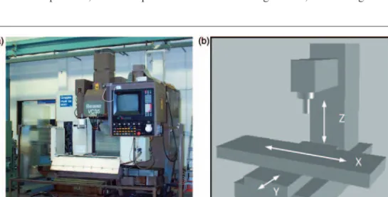
Figure1 shows the vertical 3-axis milling machine, where the tool moves in one direction (Z-axis) and the machining table moves in two directions (X- and Y-axes) on planar guide-ways. The Fanuc CNC con-trols all machine tool functions. The spindle speed can be controlled from 63 r/min to 5500 r/min and the maximum axis feed rate is 10 m/min. The machine utilises electrical feed drives with direct current (DC) feed motors. The Contraves spindle drive unit provides four quadrant operations to a separ-ately excited DC motor and provides a constant torque ranging from 63 r/min to 1140 r/min and
>1140 r/min, a constant power (8.18 kW) to the max-imum 5500 r/min.
Experimental modal analysis
Døssing,23,24 Evans25 and Richardson26,27 define the process of determining all modal parameters within the frequency range of interest to form a mathemat-ical dynamic model. They declare that the modes of vibration of the structure are the natural frequen-cies at which the structure predominant motion has a well-defined waveform. They demonstrated that the applied input force is measured with a force trans-ducer and the vibration outputs are measured at a number of points along the structure using displace-ment, velocity or acceleration transducers. This method measures the FRF between two points of a structure and the modal frequencies, mode shapes and
damping can be found from all the FRFs, except those for which the excitation or response is in a nodal position. Frequency response measurements in all three axes were made not only using excitation from either an electro-hydraulic shaker or instrument hammer but also using light cutting test forces. This methodology was applied to the machine under review and was covered in detail by Haase et al.28 and the results are summarised in Tables 1 and 2. 1. Figure 2(a) shows the compliance FRF, where the
relative vibration between tool and machine table was measured using a displacement transducer (legend shows five different loop gains).
2. Figure 2(b) shows the accelerance, where the vibra-tion was measured at the tool tip (legend shows: blue – tool to tool; red – tool to machine column; green – tool to ballscrew housing). The compliance between tool and machine table confirmed the measurements made and shown in Table 1. The accelerance of the tool tip however showed the dynamics of the spindle were >200 Hz. This con-firms the fact that the vibration source of the spin-dle drive at 300 Hz was amplified through the structure. Figure 2(b) also shows the difference in vibration amplitude between the spindle/headstock and the rest of the machine structure (e.g. ballscrew nut). The planar guide-way seemed to be relatively stiff compared to the spindle/headstock as indi-cated by Døssing.24
3. Figure 2(c) shows the FRF of the tool spindle structure (X-axis), which was measured with a sensor on the spindle housing.
4. Figure 2(d) shows the FRF of the tool spindle structure (Y-axis), which was measured with a sensor on the spindle housing.
5. Figure 2 (e) shows a cutting process-simplified model similar forX- andY-axes.
6. Figure 2(a), (c) and (d) shows no difference in the resulting FRFs, indicating that the mechanical
structure is behaving in a linear fashion. Ideally, the input signal to the shaker needs to excite every frequency with the same energy. The spectrum analyser used here (HP 3566A) could generate white noise and swept sine in order to identify an unknown system.
Integration of the adaptive
control system
Active work holder, actuators and sensors
The designed active workpiece holder allows the work-piece to move in two directions, which counteracts
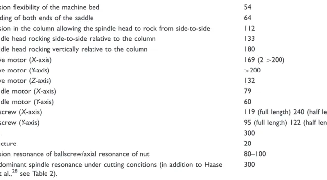
static and dynamic deflections caused by the cutting process. Each actuator moves its axis through a flexure guide system, which allows high resolution as it does not suffer from any stiction, friction and backlash. A single axis of the flexure guide system is very flexible in the proposed direction of movement but restricted or very stiff in the other two directions (Figure 3(a)). The inner axis nests into the outer axis (Figure 3(b)), reduces the weight to be moved significantly and also keeps the dimensions much smaller. The inner table, where the workpiece is mounted, will move in two-axes (X- andY- axes), the middle frame only in one axis (X -axis) and the outer reference frame does not move at all. To allow movement, under large cutting forces in Table 1. Modal analysis and frequency response measurements of the machine tool.
Source or cause of vibration Frequency (Hz)
Torsion flexibility of the machine bed 54
Bending of both ends of the saddle 64
Torsion in the column allowing the spindle head to rock from side-to-side 112 Spindle head rocking side-to-side relative to the column 133 Spindle head rocking vertically relative to the column 180
Drive motor (X-axis) 169 (2>200)
Drive motor (Y-axis) >200
Drive motor (Z-axis) 132
Spindle motor (X-axis) 79
Spindle motor (Y-axis) 60
Ballscrew (X-axis) 119 (full length) 240 (half length) Ballscrew (Y-axis) 95 (full length) 122 (half length)
Belt 300
Structure 20
Torsion resonance of ballscrew/axial resonance of nut 80–100 Predominant spindle resonance under cutting conditions (in addition to Haase
et al.,28see Table 2).
300
Table 2. Summary of measured frequency tests under non-cutting and cutting conditions.
Measurements taken for:
(a) Non-cutting: spindle running at 3000 r/min
(b) Cutting: A ø100 mm face mill with eight cutting edges and the same work-piece, material (mild steel) and dimensions (width of workpiece is the width of cut) have been used for all the tests. For each set of parameters (feed rate, spindle speed) the axial depth (aa) of cut was increased until chatter
occurred (2–4 mm). The cutting parameters were 410 r/min (383 actual on calibration) spindle speed and 267 mm/min feed rate.
Predominant frequencies in order of magnitude (Hz). Other frequencies present
1. Non-cutting: spindle housing 300
2. Cutting (aa¼2 mm):X-axis acceleration spindle housing (stable cutting) 449, 300,700
3. Cutting (aa¼4 mm):X-axis acceleration spindle housing (unstable cutting) 449, 550, 610
4. Cutting (aa¼2 mm):Y-axis acceleration spindle housing (stable cutting) 400, 300, 449
5. Cutting (aa¼4 mm):Y-axis acceleration spindle housing (unstable cutting) 449, 400, 550
6. Cutting (aa¼2 mm): spindle current (stable cutting) 300
7. Cutting (aa¼4 mm): spindle current (unstable cutting) 300þharmonics
8. Cutting: (aa¼2–3 mm) sound pressure (stable cutting) 300þharmonics
9. Cutting: (aa¼4 mm) sound pressure (unstable cutting) 449, 400
10. Cutting: tooth pass frequency 54.7
the Z-direction, the outer reference frame rests on shim steel (200mm). The necessary additional pre-load of the lead titanium–zirconate (PZT) actuators can be provided through MUBEAÕdisc springs.
The actuator in this case i.e. the piezo-electric type produces a displacement proportional to an electrical input. The integrated sensors used for the control pur-poses are: microelectromechanical (MEM) accelerom-eters, piezo-electric force sensor load washers, strain gauges and humidity sensors. The MEM accelerom-eters measure direct acceleration in two axes and are integrated into the active work holder and two into the spindle housing. The piezo-electric force sensor load washers measure the cutting force in the two axes. The strain gauges measure the direct displace-ment of the high resolution guide-way system in the two axes.
Control algorithm and memory
The control algorithm used stems from adaptive feed-forward control theory, where generally the system between the reference sensor and control source (actu-ator) is controlled by a digital filter as proposed by Hansen and Snyder.29 The impulse response of the digital filter is tuned by an automatic control algo-rithm, which has the ability to attenuate periodic and deterministic signals even when the disturbance is time varying (machine tool chatter).
Adaptive control for active control of the
machine vibration
The theory for continuous methods of vibration con-trol, modelling using digital filters and the adaptive Figure 2. Modal testing FRFs: (a) between machine tools and tool tip; (b) tool FRF (accelerance) comparison with other parts of the structure; (c) tool–spindle housingX-axis; (d) tool–spindle housingY-axis and (e) block diagram of cutting process dynamics. FRF: frequency response function.
digital filters have been covered in detail by Lockwood et al.30 and Haase et al.31 The digital signal processing (DSP) algorithms and the adaptive digital filter theory were detailed and options critically discussed for evaluation in part 1.30 Part 231 investi-gated an experimental active – vibration control system applied to a cantilever structure tuned to 400 Hz and excited by recorded chatter vibration from the machine under review.
The experimental validation work covered in part 231and fully reported30showed promising results fol-lowing the testing of adaptive finite impulse response (FIR) feedforward controllers using filtered-X LMS algorithm (FXLMS) proposed by Kuo and Morgan;32an adaptive FIR feedback controller using the error signal as the reference signal (FXLMS algo-rithm) proposed by Hakansson33 and Stothers et al.;34and finally, an adaptive FIR feedback control-ler using internal modal control (IMC) FXLMS algorithm proposed by Morani and Zafiriou.35
The simulation results obtained for the cantilever rig30,31 was used as a guide to the best algorithm for use with the machine under review, which demon-strated that the LMS algorithm is not stable over the whole frequency band because the dynamics of the secondary path were not included in the algo-rithms. To compensate for this, the digital filter
of the secondary path model is used in conjunction with the LMS algorithm. This is known as the FXLMS algorithm and demonstrated stability over the whole frequency bandwidth. As the reference signal is not available on a vibrating machine tool struc-ture, the adaptive feedback controller technique using IMC was considered the best option when considering performance and robustness.35
Adaptive control theory
The active control uses adaptive filters in order to control the plant or dynamic system. It is important to note that the signals need to be converted between three different domains: (a) digital, (b) electrical and (c) mechanical (see Figures 4(a) and 5). To improve the quality of the signal, smoothing filters and anti-aliasing filters are added.
Consider the well-known LMS or stochastic gradi-ent algorithm illustrated by Widrow and Stearns36
hnþ1¼hn2enXn ð1Þ
If the filter is an infinite impulse response filter (IIR), the LMS algorithm of Feintuch illustrated by Hayes37 can be used as a computationally simple algorithm to update feedforward (numerator) and feedback Figure 3. The design of the universal active workpiece holder for vertical machining centres (two degrees of freedom): (a) design lay-out and (b) the actual system after being built.
(denominator) filter weights and was considered appropriate for the identification filter (Figure 4(c)) where
aiþ1¼ai2aeixi ð1aÞ biþ1¼bi2beixi1 ð1bÞ
The Feintuch algorithm37was used to estimate the secondary path loop for both the acceleration and force feedback systems (see Figure 4(c)). The FXLMS was used for the adaptive control and is explained below resulting in equation (2).
Apart from the transfer function of the secondary path, which includes the dynamics of DAC (digital to analogue converter), reconstruction filter, power amp-lifier, actuator, error sensor, anti-aliasing filter and ADC (analogue to digital converter), the model remains the same as the one for system identification
where the error becomes zero if the digital filter converges to the same transfer function as the primary path.
A digital feedforward system in comparison with a feedback system has the theoretical potential to cancel a harmonic signal down to zero, because the error signal monitors only the performance of the control-ler, whereas the reference signal is used as a controller input. Feedback systems in comparison use the error signal as the controller input. By taking a harmonic excitation, for example, the controller may go unstable when the error is reduced to such an extent that the controller is supplied only with the uncorre-lated noise of the vibration sensor.
A simple adaptive feedback controller could use the error measurements for both error and reference signal. Owing to the correlation between reference and error signal, care must be taken with the fact Figure 4. (a) Typical parts of an adaptive control scheme, (b) FX LMS FIR adaptive and (c) Feintuch IIR identification algorithms. FXLMS: filtered-X LMS algorithm; FIR: finite impulse response; IIR: infinite impulse response filter.
that there is no guarantee that the error surface will have only one global minimum as it was in the feed-forward case. In order to add robustness to such sys-tems, a leakage factor can be introduced to the FXLMS algorithm (equation (2)), to weight the filter coefficients as shown by Elliot.38
Equation (1) becomes
hnþ1¼hn2enx0nðleakage factor 0551Þ ð2Þ Also, the FXLMS algorithm pre-filters the refer-ence signalxnwith an estimated digital model of the
secondary path, so that the error signal and filtered reference signalx´nare aligned in time to give a valid
cross-correlation estimate as stated by Kuo and Morgan.32 The leakage factor prevents the adaptive filter reducing the error signal down to zero. The amount of leakage determines the amount of vibra-tion left in the system. This algorithm is very practical for dealing with possible instabilities in adaptive feed-back systems as related by Hakansson33and Stothers et al.34 Methods for transforming a feedback design problem into a feedforward one with all its associated advantages was also utilised as suggested by Morani and Zafiriou,35and Morani.39
From Figure 4(b), the optimum filter solution for direct system identification using adaptive filters is
eðnÞ ¼dðnÞ yðnÞ ð3Þ EðzÞ ¼PðzÞXðzÞ HðzÞXðzÞ ð4Þ
For the optimum solution, e(n) converges to zero !Hoptimum(z)¼P(z)
For adaptive control, which includes the dynamics of a secondary path, the optimum filter solution will be
eðnÞ ¼dðnÞ sðnÞ yðnÞ ð3aÞ EðzÞ ¼PðzÞXðzÞ HðzÞSðzÞXðzÞ ð4aÞ And H(z)¼A(z)þB(z) for Feintuch IIR LMS
identification filter (5)
For the optimum filter solution, e(n) converges to zero!Hoptimum(z)¼P(z)/S(z)
In other words, the optimum filter Hoptimum(z) has to model P(z) and an inverse model of S(z). This requires an IIR filter or high-order FIR filter. For the adaptive filter using the standard LMS algorithm, the presence of the secondary path means that the difference between the filter output y(n) and desired signal d(n) is no longer available to update the filter coefficients. As the LMS algorithm uses an instantaneous estimate of the cross-correla-tion (e(n) * x(n)) to update the filter coefficients, for adaptive control applications, the phase characteris-tics of the secondary path would distort this cross-correlation estimate, because the reference signal x(n) is not ‘aligned’ correctly with the error signal e(n). In practical terms, this means that the LMS algorithm will generally cause instabilities for adaptive control, because of the presence of the sec-ondary path.
Stable cutting tests on a 3-axis
machining centre with integrated
active vibration system
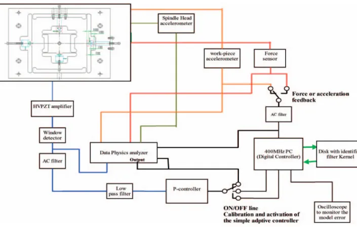
Integration of the adaptive feedback controller
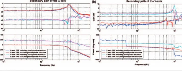
Figure 5 shows the schematics of the experimental setup for the adaptive feedback controller where the traditional and feedback structure was used (see section ‘Adaptive control theory’). The feedback transducer was either the workpiece accelerometer or the force sensor located on the piezo-electric active workpiece holder. The digital controller platform was a 400 MHz PC in order to provide enough pro-cessing power to run the adaptive FIR filter control-ler (FXLMS) in the IMC feedback structure mode at a suitable sampling frequency. The adaptive FIR LMS controller routine written in Borland Cþþ, updated for the FXLMS algorithm feedforward and feedback (IMC feedback structure mode). The secondary path model was identified off-line; and the kernel was loaded into the algorithm via a disk. The non-parametric secondary path FRF was measured using the HP spectrum analyser by applying white noise excitation through the piezo-electric actuator system. A parametric model was then identified by use of the MATLAB-S function package, and the filter kernel was designed using the MATLAB filter design tool and signal processing boxes. Identification of secondary path FRFs was carried out off-line and showed no significant difference with or without tooling fittedbut on other applica-tions it can have an effect. Also, no significant dif-ference was shown in the FRFs of the secondary path for both force and acceleration sensor systems so the same kernel was used for both (Figure 6). The Data Physics system analyser was integrated into the system to analyse performance. Table 3 shows theparameter settings for the adaptive acceleration and force feedback controller systems.
Cutting tests to evaluate force and accelerometer
feedback sensors
1. Several cutting tests were carried out to check on the performance repeatability. Figure 7 shows the performance effect of the adaptive piezo-electric control system when using the measured vibra-tions (acceleration) as a feedback signal for a stable cutting process.
2. The next sensor to be tested by the adaptive con-troller was the dynamic cutting force feedback, by the use of filters to separate the dynamic and static cutting forces. Feeding the static cutting force back to the controller would effectively have reduced the system stiffness because the actuator system would try to avoid the cutting process com-pletely by moving the actuator in the opposite dir-ection to the feed. To avoid this problem, a high-pass filter was used to feed only the dynamic cut-ting force back to the controller.
3. Figure 8 illustrates the performance of the adap-tive force feedback control for stable face milling operation.
4. Figure 9 compares the surface just before and after the adaptive force feedback controller was activated. 5. Table 4 summarises the overall performance and shows that roughness and waviness measured were improved using three-dimensional (3D) surface measurement techniques defined by Jiang et al.40 and Jiang and Blunt.41
6. Figures 7 and 8 confirm the result by measuring the spectral density of the system from strategic accelerometers placed on the workpiece and spin-dle housing before and after the controller is activated.
Figure 7. Performance of the adaptive acceleration feedback control system (Y-axis) on a stable cutting operation: (a) time response and (b) power spectral density.
Figure 8. Performance of the adaptive dynamic force feedback control system (X-axis) on a stable cutting operation: (a) time response and (b) power spectral density.
Table 3. The parameter settings of the adaptive acceleration and force feedback controller.
Accelerometer controller parameters Force sensor controller parameters
Adaptive feedback controller Secondary path identification Adaptive feedback controller Secondary path identification Adaptive algorithm Leaky FXLMS Feintuch IIR LMS Leaky FXLMS Feintuch IIR LMS
Filter 35th FIR 35th IIR 35th FIR 35th IIR Adaptive step size 0.1 (X-axis), 0.005 (Y-axis) 0.00005 0.001 0.00005 Leakage factor 1 – 0.9999 – Sampling frequency 5000 Hz 5000 Hz 5000 Hz 5000 Hz Reconstruction filter Fourth-order Butterworth
(4 kHz cut off) Fourth-order Butterworth (4 kHz cut off) Fourth-order Butterworth (2 kHz cut off) Fourth-order Butterworth (2 kHz cut off) Digital gain 1 3.0 (X-axis), 1.0 (Y-axis) 1 3.0 (X-axis), 1.0 (Y-axis) Analogue gain 4.5 (X-axis), 3.0 (Y-axis) 1.0 2.5 (X-axis), 1.0 (Y-axis) 1.0
Note that:
Figure 9 reveals the reduction in the vibration level the force feedback control system has achieved.
Active vibration control of a heavy and
unstable cutting operation
The final experimental tests were conducted to con-trol chatter vibration using the developed piezo-electric active vibration control system. The cutting conditions for all the following tests were carried out on mild steel and the parameters used were: Dc – 100 mm face mill; m: eight inserts; n – 477 r/min spindle speed;f– 133 mm/min feed rate;ar – 76 mm width of cut—width of the workpiece;aa– 2– 3 mm axial depth of cut and 0–8 mm tool offset. The cutting operation was to increase the axial depth of cut until the cutting process became unstable and on the brink of chatter.
For an unstable cutting process, the accelerometer was considered the better solution. The main chatter frequency of this machine using the same face mill was about 450–460 Hz, which is the ideal frequency for an accelerometer. Therefore, the accelerometer was used as feedback sensor for trying to control unstable cut-ting operations (chatter). The control parameters were the same as shown in Table 1 except for a reduced analogue gain.
Note that:
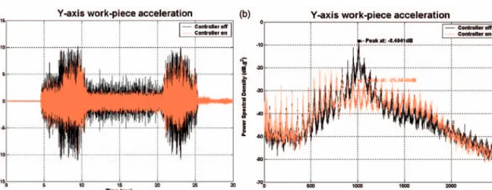
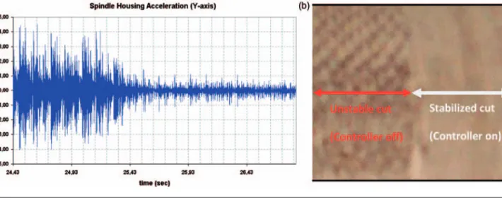
. Figure 10 shows the effect the adaptive control system has made for an unstable cutting oper-ation; the surface finish improvement shown in Figure 10(b) was captured with a digital camera.
. Figure 10(a) and (b) shows that the system success-fully controlled chatter vibration with the result that both the vibration level and the generated surface were improved significantly (no chatter marks).
Summary
. Vibration analysis of the machine helped to focus on the project (Tables 1 and 2).
. New types of silicon MEM accelerometers have successfully been used to measure machine tool vibration.
. Active vibration control, actuators, sensors and adaptive control algorithms have been vigorously studied.
. Adaptive filter routines have been written in MATLAB/SIMULINK and Cþþ. These routines have successfully been used to estimate and fit off-and on-line mathematical models to an FRF from modal tests. The identified structural models have helped to develop a simulation program for the adaptive vibration controller. All the adaptive Figure 9. The generated surface (a) with (b) and without the controller activation (stable operation).
Table 4. Overall improvement through the adaptive force feedback controller (stable cutting operation).
Adaptive force controller off Adaptive force controller on
Surface roughnessSqin Z-direction
(Roughness wavelength 0–0.8 mm) 3.493mm 2.748mm Surface wavinessSqin Z-direction
(Waviness wavelength 0.8–5 mm) 1.148mm 0.93mm Reduction of the dynamic cutting force
for theX-axis
6–7 dB (55%) at 7.4 Hz and 59 Hz
(Spindle run out and tooth pass frequency) Reduction of the dynamic cutting force
for theY-axis
6–7 dB (55%) at 7.4 Hz and 59 Hz
control and identification routines developed here have been added to our standard MATLAB/ SIMULINK library.
. The novel universal prototype and demonstration system (Figure 3) for active vibration control on a 3-axis milling machine has been designed and built. The 2-axis system uses a novel high-resolution flex-ure guiding system and its integrated sensors are able to measure the cutting force, direct acceleration and direct displacement. The actuators can move each axis about 6mm with nanometre resolution. The system is protected from cutting fluid and hot chips and can withstand cutting forces>12.5 kN.
. The Feintuch algorithm was used to estimate the secondary path loop for both the acceleration and force feedback systems (Figure 4(c)) while the FXLMS was used for the adaptive control (section ‘Adaptive control theory’).
. Acceleration feedback was preferred to force feed-back for the chatter frequencies experienced.
Conclusion
. Active vibration control applied to a milling machine using digital adaptive filters has been demonstrated to have significant potential for improving machine’s performance under stable and non-stable conditions.
. The developed active acceleration feedback vibra-tion control system has been successfully used to control and reduce the vibration of a stable face milling operation by up to 16–17 dB (Y-axis: 85% at 1000 Hz;X-axis: 70% at 600 Hz).
. Although only two axes in the plane perpendicular to the rotating spindle axes were under control, the adaptive dynamic cutting force feedback control system has improved the surface finish with 21.3% roughness and 18.9% waviness (Figure 9 and Table 4).
. The developed active acceleration feedback vibra-tion control system has been successfully used to control and reduce the vibration of an unstable face milling operation. The system was able to sta-bilise the cut and eliminate chatter vibration. The vibration level at significant modal frequencies has been reduced significantly to 23 dB (92.9%) at 339 Hz and 24.5 dB (93.9%) at 1024 Hz (Figure 11(a) and (b)), the surface finish tests indi-cated that all chatter marks had been removed (Figure 10).
. The >90% reductions at the modal frequencies would suggest that greater MRRs and a significant reduction in tool wear could also be achieved but exhaustive tests have not yet been carried out because the system is a prototype.
. Critical comparison with Rashid and Nicolescu:22 1. A common algorithm, namely the FXLMS was
used for the adaptive control, yet was devel-oped independently. Our exhaustive algorithm tests put into the public domain by Lockwood et al.30and Haase et al.31 showed critical com-parisons with other algorithm types and pre-dated Rashid & Nicolescu (22). We concluded that the IMC FXLMS for our adaptive control application and for the Feintuch algorithm to be used to determine the secondary path loop (sections ‘Adaptive control for active control of the machine vibration’ and ‘Adaptive control theory’).
2. Our work-holding system was purpose built, whereas Rashid and Nicolescu22 adapted a Dynafix palletised work-holding system, which was satisfactory for their heavier machining application.
3. They utilised force feedback, whilst we exam-ined both force (stable operation) and acceler-ation feedback (unstable operacceler-ation). We found the acceleration feedback to be more advanta-geous at the chatter frequencies experienced. Figure 10. Control of chatter vibrations using the adaptive active vibration control system: (a) reduction in vibrations and (b) the improved surface finish.
For an unstable cutting process, the accelerom-eter was considered the better solution (see sec-tion ‘Cutting tests to evaluate force and accelerometer feedback sensors’).
4. The adaptive controller utilising dynamic cut-ting force feedback needed high-pass filters to separate the dynamic and static cutting forces. The surface finish and vibration spectrum improvements before and after the adaptive force feedback controller was activated and are covered in ‘Cutting tests to evaluate force and accelerometer feedback sensors’ section and are illustrated in Figures 8 and 9. Table 4 summarises the overall performance using 3D surface characterisation measurement tech-niques pioneered by Jiang et al.40 and Jiang and Blunt,41where the roughness and waviness measurements were significantly improved. 5. Rashid and Nicolescu22claimed a surface finish
improvement (ca 41% on roughness measure-ment) for their larger depth of cut operation
(ca 10 mm depth of cut) on a stable milling operation for mild steel and demonstrated an improved tool wear performance. Their rough-ness measurement was assumed (not stated) to be measured using a 2D measuring instrument. Our surface finish improvements were 21.3% roughness and 18.9% waviness using a 3D mea-suring instrument.
6. No attempt was made by Rashid and Nicolescu22 to compensate for chatter.
7. In conclusion, both parties confirm improved performance (surface finish/tool wear) for stable milling operation using dynamic force feedback systems. On our smaller machine we have demonstrated that the system was able to stabilise the cut and eliminate chatter vibration (ca 93% reduction) utilising acceleration feed-back, which should also significantly improve the MMR.
8. Both conclude that their respective research programmes were in an evolutionary phase Figure 11. Improvement of the vibration level through the active chatter control system: (a) time response and (b) power spectral density.
with problems that need to be addressed in order to satisfy system integration, robustness and safety hazard requirements. Nevertheless, both clearly demonstrated successful research programmes in need of further development and exhaustive testing.
Suggestions for further work
1. Reduce the work holder guide-way stiffness and increase the maximum stroke up to 8–10mm could optimise the existing 2-axis system relatively easily.
2. The cutting trials could be extended to peripheral cutting operations and this should bring better results as the generated surface has the same dir-ection as the axes under control.
3. Faster, more modern, DSP-based, digital control-ler platform could be used. More computational power would make it possible to increase the sam-pling frequency, model order and to use other recursive adaptive algorithms.
4. A faster digital computer may also allow for the on-line identification of the secondary path during cutting. The identification routine would run con-tinuously and the secondary path be updated periodically.
5. A major improvement would be the integration of the whole actuator system into the spindle head of the machine. Although this would mean that it was machine specific, it would have the advantage of controlling the spindle and tool directly and the table would be free to mount a workpiece of any size which is not possible with the current system. 6. Exhaustive tests on MMR and tool wear
improve-ment should be carried out. Funding
This research was supported by EPSRC with grant nos GR/R13401/01 and GR/R1335186/01.
Conflict of interest
None declared.
Acknowledgements
The authors would like to thank the EPSRC for grant sup-port and also the industrial collaborating partners.
References
1. Ford DG. Machining to microns – error avoidance or compensation. In: Conference proceedings of LAMADAMAP on laser metrology and machine perform-ance II, Southampton Institute, UK, 1995, pp.41–52. 2. Lui XW, Cheng K, Webb D, et al. Improved dynamic
cutting force model in peripheral milling, Part II: experi-mental verification and prediction. Int J Adv Manuf Technology2004; 24: 794–805.
3. Fischer U. Fachkunde metall. Zurich, Switzerland: Europa Verlag, 1996.
4. Tlusty J. High speed machining. CIRP Ann: Manuf Technol1993; 42: 733–738.
5. Tlusty J and Polacek M. The stability of the machine tool against self-excited vibration in machining. In: Production engineering research conference ASME, Pittsburgh, 1963.
6. Tobias SA.Machine tool vibration. Glasgow: Blackie & Son, 1965.
7. Kalmar-Nagy T, Stepan G and Moon FC. Subcritical Hopf bifurcation is the delay equation model for machine tool vibrations. Nonlinear Dyn 2001; 26: 121–142.
8. Weck M.Metechnische Untersuchung und Beurteilung. Berlin, Germany: Springer Verlag, 1997.
9. Engin S and Altinas Y. Mechanics and dynamics of general milling cutters Part 1: helical end mills. Int J Mach Tools Manuf2001; 41(15): 2195–2212. 10. Engin S and Altinas Y. Mechanics and
dynamics of general milling cutters Part 2: inserted cutters. Int J Mach Tools Manuf 2001; 41(15): 2213–2231.
11. MAL (Manufacturing Automation Laboratories Inc.) www.maline.com.
12. Hardwick B. Identification and solution of machine too chatter problems. In: Conference proceedings of LAMADAMAP on laser metrology and machine performance I, Southampton Institute, UK, 1993, pp.123–139.
13. Janocha H. Adaptronics and smart structures. Berlin, Germany: Springer Verlag, 1999.
14. Pneumont A. Vibration control of active structures. Dordrecht, the Netherlands: Kluwer Academic, 1997.
15. Cao W, Cudney H and Waser R. Smart materials and structures. Proc Natl Acad Sci USA 1999; 96: 8330–8331.
16. Rojas J and Liang C. Experimental investigations of active machine vibration control. Proc SPIE 1996; 2721: 373.
17. Pan G, Xu H, Kwan CM, et al. Modelling and intelli-gent chatter control strategies for a lathe machine. Control Eng Pract1996; 12: 1647–1658.
18. Pan G. MDSP-200 and its application in vibration iso-lation. Technical Report, Intelligent Automation Inc, 1995.
19. O’Reagan S, Miesner J, Aitken R, et al. Machine tool chatter reduction via active structural control. In: Second European conference on smart structures and materials, Glasgow, UK, 1994.
20. Jang JL and Tarng YS. A study of the active vibration control of a cutting tool.J Mater Process Technol1999; 95: 78–82.
21. Ehmann C, Scho¨nhoff and Nordmann R. Aktiv Schwingungsda¨mpfung bei Portalfra¨smachinen. Technical Report, University of Darmstadt, Germany, 2001.
22. Rashid A and Nicolescu CM. Active vibration control in palletised workholding system for milling.Int J Mach Tools Manuf2006; 46: 1626–1636.
23. Døssing O. Strukturen pru¨fen – Teil 1: Mechanische Beweglichkeits-Messungen, Bru¨el & Kjær Handbook. Glostrup, Denmark: K. Larsen & Søn A/S, 1989.
24. Døssing O. Strukturen pru¨fen – Teil 2: Modalanalyse und Simulation, Bru¨el & Kjær Handbook. Glostrup, Denmark: K. Larsen & Søn A/S, 1989.
25. Evans DJ. Modal testing: Theory and practice. Letchworth, UK: Research Studies Press Ltd, 1984. 26. Richardson M. Measurement and analysis of the
dynamics of mechanical structures. In: Hewlett Packard conference for automotive and related industries, Detroit, MI, 1978.
27. Richardson M. Global curve fitting of frequency response measurements using the rational frequency polynomial method. In: 3rd IMAC conference, Orlando, FL, 1985.
28. Haase F, Lockwood S and Ford DG. Vibration model-ling of machine tool structures. In:Conference proceed-ings of LAMDAMAP, University of Birmingham, UK, 2001, pp.137–146.
29. Hansen CH and Snyder SD.Active control of sound and vibration. London, UK: Chapman & Hall, 1997. 30. Lockwood S, Haase F and Ford DG. Active vibration
control of machine tool structures –Part 1: DSP algo-rithms. In: Conference proceedings of LAMDAMAP, 2003, pp.441–450.
31. Haase F, Lockwood S and Ford DG. Active vibration control of machine tool structures –Part 2: An experi-mental active vibration system. In:Conference proceed-ings of LAMDAMAP, 2003, pp.451–460.
32. Kuo SM and Morgan DR.Active noise control systems. New York: Wiley, 1996.
33. Hakansson L. Adaptive active control of machine tool vibration in a lathe. Doctoral Thesis, Lund University, Sweden, 1999.
34. Stothers IM, Saunders TJ, McDonald AM, et al. Adaptive feedback control of sun roof flow oscillations. Proc Inst Acoust1993; 15: 383–393.
35. Morani M and Zafiriou E. Robust process control. Englewood Cliffs, NJ: Prentice-Hall, 1989.
36. Widrow B and Stearns SD.Adaptive signal processing. Englewood Cliffs, NJ: Prentice Hall, 1985.
37. Hayes MH.Statistical digital processing and modelling. New York: Wiley, 1996.
38. Elliot S.Signal processing for active control. New York: Academic Press, 2001.
39. Morani M. Implications for internal modal control for PID controllers. In: American control conference, Chicago, IL, 1992, Vol. 2, pp.661–666.
40. Jiang X, Blunt L and Stout KJ. Development of a lift-ing wavelet representation for characterisation of sur-face topography.Proc R Soc Lond A2000; 456: 1–31. 41. Jiang X and Blunt L. Surface analysis techniques to
optimise the performance of CNC machine tools. In: Proceedings of LAMADAMAP on laser metrology and machine performances VI, University of Huddersfield, UK, 2003, pp.107–117.
Appendix
Notation
a filter kernel Feintuch IIR LMS algorithm (numerator)
aiþ1 new feedforward weighting coefficient value for Feintuch IIR LMS algorithm (numerator)
ai previous feedforward weighting
coeffi-cient value for Feintuch IIR LMS algorithm (numerator)
b filter kernel Feintuch IIR LMS algo-rithm (denominator)
bi previous feedback weighting coefficient value for Feintuch IIR LMS algorithm (denominator)
biþ1 new feedback weighting coefficient value for Feintuch IIR LMS algorithm (denominator)
d(n) plant output
E(z) error signal (zdomain) e(n) scalar error signal
ei current error signal for Feintuch IIR
LMS algorithm
en current error signal for filtered-X FIR
LMS algorithm h filter kernel
h(n) the impulse response is the equivalent of the transfer function H(z) in the z domain.
hn current coefficient value for LMS
algorithm
hnþ1 new coefficient value for LMS algorithm
H(z) Feedforward transfer function (z domain)
P(z) primary path transfer function (z domain)
S(z) secondary path transfer function (z domain)
Solidus /: Division x(n) input signal
xi current input signal for Feintuch IIR
LMS feedforward algorithm
xi1 last time input signal for Feintuch IIR LMS feedback algorithm
xn current input or excitation signal for
LMS algorithm
x´n filtered input or excitation signal for
filtered-X FIR LMS algorithm X(z) input signal (zdomain)
y(n) the filter output signal is a linear combination of the previous input and output samples weighted with the coef-ficients,a (numerator) andb
(denominator) z Zdomain operator
m adaptation coefficient for LMS algo-rithm. Determines the step size used for each iteration and must be set small enough to obtain stability of the algorithm.
ma adaptation coefficient for Feintuch IIR LMS feedforward algorithm.
Determines the step size used for each iteration and must be set small enough to obtain stability of the algorithm
mb adaptation coefficient for Feintuch IIR LMS feedback algorithm. Determines the step size used for each iteration and must be set small enough to obtain stability of the algorithm